EP1034890A2 - Verfahren und Vorrichtung zum Bestrahlen mit verschiedenartigen Strahlmitteln - Google Patents
Verfahren und Vorrichtung zum Bestrahlen mit verschiedenartigen Strahlmitteln Download PDFInfo
- Publication number
- EP1034890A2 EP1034890A2 EP00104375A EP00104375A EP1034890A2 EP 1034890 A2 EP1034890 A2 EP 1034890A2 EP 00104375 A EP00104375 A EP 00104375A EP 00104375 A EP00104375 A EP 00104375A EP 1034890 A2 EP1034890 A2 EP 1034890A2
- Authority
- EP
- European Patent Office
- Prior art keywords
- blasting
- normal conditions
- under normal
- solid state
- gaseous
- Prior art date
- Legal status (The legal status is an assumption and is not a legal conclusion. Google has not performed a legal analysis and makes no representation as to the accuracy of the status listed.)
- Withdrawn
Links
Images


Classifications
-
- B—PERFORMING OPERATIONS; TRANSPORTING
- B24—GRINDING; POLISHING
- B24C—ABRASIVE OR RELATED BLASTING WITH PARTICULATE MATERIAL
- B24C1/00—Methods for use of abrasive blasting for producing particular effects; Use of auxiliary equipment in connection with such methods
- B24C1/003—Methods for use of abrasive blasting for producing particular effects; Use of auxiliary equipment in connection with such methods using material which dissolves or changes phase after the treatment, e.g. ice, CO2
-
- B—PERFORMING OPERATIONS; TRANSPORTING
- B24—GRINDING; POLISHING
- B24C—ABRASIVE OR RELATED BLASTING WITH PARTICULATE MATERIAL
- B24C11/00—Selection of abrasive materials or additives for abrasive blasts
-
- B—PERFORMING OPERATIONS; TRANSPORTING
- B24—GRINDING; POLISHING
- B24C—ABRASIVE OR RELATED BLASTING WITH PARTICULATE MATERIAL
- B24C7/00—Equipment for feeding abrasive material; Controlling the flowability, constitution, or other physical characteristics of abrasive blasts
- B24C7/0046—Equipment for feeding abrasive material; Controlling the flowability, constitution, or other physical characteristics of abrasive blasts the abrasive material being fed in a gaseous carrier
Definitions
- the invention relates to a method for blasting a workpiece with blasting media in a solid state of aggregation, with the blasting media in at least one blasting system metered at least one gas stream with the gas stream to a blasting device promoted and blasted on the workpiece to be machined
- the invention also relates to a device for blasting a workpiece with blasting media in solid physical state comprising at least one blasting system with means for Dosing the blasting media into at least one gas stream, one or more Blasting hoses leading from a blasting system to a blasting device which the blasting media are blasted onto the workpiece to be machined.
- Blasting as a treatment method with blasting media is used in numerous industrial applications Applications known.
- the known beam treatment methods can be considered divide the blasting media into two groups.
- the first group concerns blasting with conventional blasting media such as in particular Quartz sand (sandblasting), but also with other conventional abrasives such as steel gravel, cast iron gravel, wire grain and corundum.
- conventional blasting media such as in particular Quartz sand (sandblasting)
- other conventional abrasives such as steel gravel, cast iron gravel, wire grain and corundum.
- These conventional ones Abrasives have the common property that the abrasives Normal conditions in a solid state of aggregation are present. They usually work abrasive. With the blasting treatment using conventional, abrasive Abrasives usually produce a lot of dust (from the bouncing Abrasives and the blasted material). This strong dust generation is mostly undesirable. In addition, they arise from the necessary disposal of the abrasive contaminated with blasted material high costs.
- blasting media are generally softer than the conventional blasting media and therefore ensure blasting treatment with less abrasiveness compared to blasting treatments with conventional blasting media in the solid state under normal conditions.
- Dry ice (CO 2 ) which has proven itself in numerous applications, should be mentioned in particular as a representative of the group of abrasives that are in fluid form under normal conditions.
- the "cleaning power" for example the blast cleaning with dry ice as the blasting medium should be larger, around the Cleaning results in terms of cleaning speed and the achieved To be able to make cleanliness more economical.
- the "cleaning power" for example the blast cleaning with dry ice as the blasting medium should be larger, around the Cleaning results in terms of cleaning speed and the achieved To be able to make cleanliness more economical.
- the present invention is therefore based on the object of a method and a To provide device of the type mentioned, by one abrasive blasting treatment with blasting media is to be shown, in which the abrasive effect of the abrasive between that of normal conditions in fluider
- the form of the abrasive and the solid state in normal conditions existing blasting media Another job is also at elastic surfaces to allow material removal and in the desired To be able to achieve dimensions.
- Another task is that of conventional abrasive blasting with solid state under normal conditions existing blasting media creates strong dust with an effective To counter dust binding.
- Dry ice (CO 2 ) is advantageously used as the first blasting agent in the gaseous state of aggregation under normal conditions due to its advantageous material properties (see above).
- all abrasive blasting media suitable for this purpose such as sand or any other inorganic, plant-based or organic blasting media, can be used as the blasting media in a solid state under normal conditions.
- the gaseous or liquid state of aggregation under normal conditions The first blasting media must be used in a solid state be cooled. By irradiation with the under normal conditions in The first blasting agent in fluid form is therefore applied to the irradiated workpiece surface Transmit cold. This leads to embrittlement of the workpiece surface and / or the buildup on the surface.
- This is the inventive Process also an effective blasting treatment of elastic workpiece surfaces possible because conventional abrasive blasting media are also used come.
- due to the cooling of the surface Embrittlement of the surface or the build-up on the surface when blasting an increase in cleaning speed and / or a reduction of abrasive consumption per area or per unit of time can be achieved.
- the coldness of the first blasting media which is present in fluid form under normal conditions, has but also another effect: due to the cold of the jet nozzle of the blasting device escaping jet consisting of cold air and blasting media occurs spontaneously to fog. This creates droplets of condensate.
- the first Blasting media therefore act as a coolant and generate the condensate droplets again enable dust binding.
- the invention thus also ensures effective dust control in a simple way
- a mixing of the in normal conditions in gaseous or liquid state of aggregate first blasting media with the under normal conditions in a solid state of aggregate second blasting media take place in a blasting machine.
- the two abrasive components be mixed accordingly in a common storage container.
- the mixing of the first and second blasting media can also take place by connecting two blasting systems in series, with a separate blasting system being provided for each blasting media component (first and second blasting media).
- first and second blasting media can be connected, for example, in such a way that in the first blasting system the first abrasive, which is present in fluid form under normal conditions, is metered in in a stream of compressed air and then connected with a largely conventional blasting system - i.e.
- blasting pressures used usually a maximum of 6 to 8 bar
- volume flows rarely more than 6 to 8 m 3 / min
- the mixing of the in normal conditions in gaseous or liquid physical state of the first abrasive and the under normal conditions in a solid state of aggregate second abrasive take place in the blasting device.
- the first blasting medium e.g. dry ice
- the advantage of the variant with two blasting hoses to the steel device is that the mixing ratio between the first and second abrasive can be chosen practically arbitrarily, because no consideration was given to excessive cooling of the blasting hose must become. This advantage is also likely to be the less significant disadvantage of something compensate for restricted handling due to the two blasting hoses.
- the first and second blasting media When the first and second blasting media are mixed in the blasting device can the first blasting media in a first blasting system in a gas stream and second conventional blasting media in a second blasting system into a gas stream be dosed. But it is also possible that from a common blasting system one blasting hose each for the first and for the second blasting media to the blasting device to be led.
- the device according to the invention can be a single blasting system with a common one Storage container and / or with a storage container for each of the first Include blasting media and for the second blasting media.
- the device a blasting system with a reservoir for the fluid in normal conditions present first abrasive and a blasting system with a reservoir for the second blasting media present in solid form under normal conditions.
- the invention opens up new areas of application for blasting technology. she offers Significant advantages, especially in jet cleaning. As conventional under normal conditions second abrasive present in a solid state all known abrasives are used. Preferred areas of application are surface cleaning, especially the removal of coatings or buildup, paint stripping, facade cleaning and the like.
- first blasting agent dry ice and as a gas for the conveying gas stream compressed air used.
- the device according to the invention shown in FIG. 1 shows a blasting system 1 with a compressed air supply 2.
- the blasting system 1 contains two storage containers, one storage container for the dry ice and a separate storage container 4 for the second blasting medium 4 which is in a solid state under normal conditions.
- the device also contains a blasting device in the form of a blasting gun 5.
- the dry ice 3 is conveyed into the blasting gun 5 via a blasting hose 6 and the second blasting means 4 via a second blasting hose 7 and mixed there.
- the blasting system 1 a common reservoir for dry ice 3 and second blasting agent 4, one of which for both blasting agent components provided blasting hose leads to blasting gun 5.
- FIG. 2 shows a device according to the invention with two blasting systems 11 and 12 connected in parallel.
- the device comprises a first blasting system for the dry ice 3 and a second blasting system 2 for the conventional, abrasive second blasting medium 4.
- the compressed air supply is divided between the blasting systems 11 and 12, a partial flow of the compressed air via line 2 to the blasting system 11 and Partial stream 2a leads to the blasting system 12.
- Dry ice is conveyed from the blasting system 11 via the blasting hose 6 to the blasting gun 5.
- the second blasting agents 4, which are guided through the blasting hose 7 from the blasting system 12 to the blasting gun 5 under normal conditions in a solid state of aggregation, are mixed with the dry ice 3 in the blasting gun.
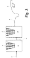
- FIG. 3 shows a device according to the invention in series connection of two blasting systems.
- the compressed air supplied from the compressed air supply via line 2 is first led into a first blasting system 13, where the compressed air jet receives the dry ice 3 from the reservoir of the blasting system 13 and is fed via line 9 into a second blasting system 14.
- abrasive blasting medium 4 from the reservoir of the blasting system 14 is mixed with the compressed air stream enriched, for example, with CO 2 pellets 3 and passed through the blasting hose 8 into the blasting gun 5.
Landscapes
- Engineering & Computer Science (AREA)
- Mechanical Engineering (AREA)
- Cleaning In General (AREA)
- Application Of Or Painting With Fluid Materials (AREA)
Abstract
Description
- Know How, "Strahlreinigen nach Maß mit Cryoclean ®", Dr. H.-J. Diehl, Linde AG, Werksgruppe Technische Gase, 2/96, 1996, Seiten 1 bis 5,
- Figur 1
- eine erfindungsgemäße Vorrichtung mit einer Strahlanlage nach dem Zwei-Schlauch-Prinzip,
- Figur 2
- eine erfindungsgemäße Vorrichtung mit zwei Strahlanlagen in Parallelsehaltung und
- Figur 3
- eine erfindungsgemäße Vorrichtung mit Hintereinanderschaltung von zwei Strahlanlagen.
Claims (13)
- Verfahren zum Bestrahlen eines Werkstücks mit Strahlmitteln (3, 4) in festem Aggregatzustand, wobei die Strahlmittel (3, 4) in mindestens einer Strahlanlage (1; 11, 12; 13, 14) in mindestens einen Gasstrom (2, 2a) eindosiert, mit dem Gasstrom zu einer Strahlvorrichtung (5) gefördert und auf das zu bearbeitende Werkstück gestrahlt werden, dadurch gekennzeichnet, daß die Strahlmittel (3, 4) sowohl bei Normalbedingungen in gasförmigem oder flüssigem Aggregatzustand vorliegende erste Strahlmittel (3) als auch bei Normalbedingungen in festem Aggregatzustand vorliegende zweite Strahlmittel (4) umfassen.
- Verfahren nach Anspruch 1, dadurch gekennzeichnet, daß Trockeneis (CO2) als bei Normalbedingungen in gasförmigem Aggregatzustand vorliegendes erstes Strahlmittel (3) eingesetzt wird.
- Verfahren nach einem der Ansprüche 1 oder 2, dadurch gekennzeichnet, daß durch die Wahl des Massenverhältnis von den bei Normalbedingungen in gasförmigem oder flüssigem Aggregatzustand vorliegenden ersten Strahlmitteln (3) zu den bei Normalbedingungen in festem Aggregatzustand vorliegenden zweiten Strahlmitteln (4) der Grad der Abrasivität der Bearbeitung bestimmt wird.
- Verfahren nach einem der Ansprüche 1 bis 3, dadurch gekennzeichnet, daß bis zu einem massenbezogenen Anteil der bei Normalbedingungen in festem Aggregatzustand vorliegenden zweiten Strahlmittel (4) in Höhe von 30 % an der Gesamtmasse der Strahlmittel (3, 4), bevorzugt bis zu 50 %, herkömmliche aus der Strahlbearbeitung mit bei Normalbedingungen in festem Aggregatzustand vorliegenden zweiten Strahlmitteln (4) bekannte Strahlschläuche (7; 8) und/oder Strahlvorrichtungen (5) einsetzbar sind.
- Verfahren nach einem der Ansprüche 1 bis 4, dadurch gekennzeichnet, daß eine Vermischung der bei Normalbedingungen in gasförmigem oder flüssigem Aggregatzustand vorliegenden ersten Strahlmittel (3) und der bei Normalbedingungen in festem Aggregatzustand vorliegenden zweiten Strahlmittel (4) in einer Strahlanlage (1; 14) stattfindet.
- Verfahren nach einem der Ansprüche 1 bis 4, dadurch gekennzeichnet, daß eine Vermischung der bei Normalbedingungen in gasförmigem oder flüssigem Aggregatzustand vorliegenden ersten Strahlmittel (3) und der bei Normalbedingungen in festem Aggregatzustand vorliegenden zweiten Strahlmittel (4) in der Strahlvorrichtung (5) stattfindet.
- Verfahren nach Anspruch 6, dadurch gekennzeichnet daß die bei Normalbedingungen in gasförmigem oder flüssigem Aggregatzustand vorliegenden ersten Strahlmittel (3) in einer ersten Strahlanlage (11; 13) in einen Gasstrom (2) und die bei Normalbedingungen in festem Aggregatzustand vorliegenden zweiten Strahlmittel (4) in einer zweiten Strahlanlage (12; 14) in einen Gasstrom (2a; 9) eindosiert werden.
- Vorrichtung zum Bestrahlen eines Werkstücks mit Strahlmitteln (3, 4) in festem Aggregatzustand umfassend mindestens eine Strahlanlage (1; 11, 12; 13, 14) mit Mitteln zum Eindosieren der Strahlmittel (3, 4) in mindestens einen Gasstrom (2, 2a), einen oder mehrere Strahlschläuche (6, 7; 8, 9), die von einer Strahlanlage zu einer Strahlvorrichtung (5) führen, aus welcher die Strahlmittel (3, 4) auf das zu bearbeitende Werkstück gestrahlt werden, dadurch gekennzeichnet, daß die Vorrichtung Mittel (1, 3, 4, 5, 6, 7, 8, 9, 11, 12, 13, 14) zum Strahlen von bei Normalbedingungen in gasförmigem oder flüssigem Aggregatzustand vorliegenden ersten Strahlmitteln (3) und bei Normalbedingungen in festem Aggregatzustand vorliegenden zweiten Strahlmitteln (4) umfaßt.
- Vorrichtung nach Anspruch 8, dadurch gekennzeichnet, daß die Vorrichtung Mittel (1; 5) zum Vermischen von bei Normalbedingungen in gasförmigem oder flüssigem Aggregatzustand vorliegenden ersten Strahlmitteln (3) und bei Normalbedingungen in festem Aggregatzustand vorliegenden zweiten Strahlmitteln (4) umfaßt.
- Vorrichtung nach Anspruch 9, dadurch gekennzeichnet, daß die Vorrichtung eine einzige Strahlanlage (1) mit einem gemeinsamen Vorratsbehälter und/oder mit jeweils einem Vorratsbehälter für die bei Normalbedingungen in gasförmigem oder flüssigem Aggregatzustand vorliegenden ersten Strahlmittel (3) und für die bei Normalbedingungen in festem Aggregatzustand vorliegenden zweiten Strahlmittel (4) umfaßt.
- Vorrichtung nach Anspruch 9, dadurch gekennzeichnet, daß die Vorrichtung eine Strahlanlage (11; 13) mit einem Vorratsbehälter für die bei Normalbedingungen in gasförmigem oder flüssigem Aggregatzustand vorliegenden ersten Strahlmittel (3) und eine Strahlanlage (12; 14) mit einem Vorratsbehälter für die bei Normalbedingungen in festem Aggregatzustand vorliegenden zweiten Strahlmittel (4) umfaßt.
- Vorrichtung nach einem der Ansprüche 8 bis 11, dadurch gekennzeichnet, daß mehrere Strahlschläuche (6, 7) mit einer Strahlvorrichtung (5) verbunden sind.
- Verwendung der Vorrichtung nach einem der Ansprüche 8 bis 12 zum Strahlreinigen von Oberflächen.
Applications Claiming Priority (2)
| Application Number | Priority Date | Filing Date | Title |
|---|---|---|---|
| DE19909718 | 1999-03-05 | ||
| DE19909718 | 1999-03-05 |
Publications (2)
| Publication Number | Publication Date |
|---|---|
| EP1034890A2 true EP1034890A2 (de) | 2000-09-13 |
| EP1034890A3 EP1034890A3 (de) | 2000-12-20 |
Family
ID=7899825
Family Applications (1)
| Application Number | Title | Priority Date | Filing Date |
|---|---|---|---|
| EP00104375A Withdrawn EP1034890A3 (de) | 1999-03-05 | 2000-03-02 | Verfahren und Vorrichtung zum Bestrahlen mit verschiedenartigen Strahlmitteln |
Country Status (2)
| Country | Link |
|---|---|
| EP (1) | EP1034890A3 (de) |
| DE (1) | DE10010012A1 (de) |
Cited By (8)
| Publication number | Priority date | Publication date | Assignee | Title |
|---|---|---|---|---|
| EP1188519A1 (de) * | 2000-08-25 | 2002-03-20 | PanGas | Verfahren und Vorrichtung zum Bestrahlen mit Strahlmitteln |
| WO2002070202A3 (de) * | 2001-03-08 | 2003-10-30 | Linde Ag | Strahlverfahren zum reinigen von rohren |
| WO2006000274A1 (de) * | 2004-06-24 | 2006-01-05 | Jens Werner Kipp | Vorrichtung und verfahren zur zuführung von flüssigem kohlendioxid |
| WO2012022510A1 (de) | 2010-08-19 | 2012-02-23 | Voestalpine Stahl Gmbh | Verfahren zum konditionieren der oberfläche gehärteter korrosionsgeschützter bauteile aus stahlblech |
| US9822436B2 (en) | 2007-05-11 | 2017-11-21 | Voestalpine Stahl Gmbh | Method for the production and removal of a temporary protective layer for a cathodic coating |
| DE102021101996A1 (de) | 2021-01-28 | 2022-07-28 | Dyemansion Gmbh | Verfahren zur Nachbearbeitung von additiv gefertigten Bauteilen durch Strahlverfahren mit Kunststoffstrahlmitteln |
| DE102022106559A1 (de) | 2022-03-21 | 2023-09-21 | Muyo Oberflächentechnik GmbH | Verfahren und vorrichtung zur vorbehandlung eines bauteils vor einem beschichtungsprozess |
| WO2024218138A1 (de) * | 2023-04-17 | 2024-10-24 | El Mustapha Baira | Verfahren zur vorbehandlung eines bauteils vor einem beschichtungsprozess und vorbehandeltes bauteil |
Families Citing this family (7)
| Publication number | Priority date | Publication date | Assignee | Title |
|---|---|---|---|---|
| DE102010020618B4 (de) | 2009-05-26 | 2014-05-28 | Jürgen von der Ohe | Verfahren zur Herstellung von CO2-Pellets oder von CO2-Partikeln mit erhöhter mechanischer Härte und Abrasivität |
| DE202011108513U1 (de) | 2011-03-14 | 2012-01-30 | Jürgen von der Ohe | Vorrichtung zur Herstellung eines Strahlmittels, Vorrichtung zum Strahlen und Strahlmittel |
| DE102011055772A1 (de) * | 2011-11-28 | 2013-05-29 | Werner Hunziker | Vorrichtung und Verfahren zum Nassstrahlen von Strahlgut |
| DE102020000018A1 (de) | 2020-01-02 | 2021-07-08 | Jürgen von der Ohe | Verfahren und Vorrichtung zur Fertigung eines kryogen-mechanisch wirkenden Strahlmittels, sowie Verfahren und Vorrichtung zum Reinigen von Bauteilen mit dem kryogen-mechanisch wirkenden Strahlmittel |
| DE102020002085A1 (de) | 2020-04-01 | 2021-10-07 | Jürgen von der Ohe | Selbst korrigierende Programmsteuerung zur Fertigung eines kryogen-mechanisch wirkenden Strahlmittels, unter Einhaltung einer effektiven Energiebilanz |
| DE202023002024U1 (de) | 2023-04-18 | 2024-01-04 | Jürgen von der Ohe | Vorrichtung zum Herstellen eines festen kryogen-mechanisch wirkenden Strahlmittels aus Wasser im Gegenstromverfahren |
| DE202025003887U1 (de) | 2025-10-07 | 2026-05-13 | Jürgen v.d. Ohe | Vorrichtung zum gleichzeitigen Herstellen und Verarbeiten eines festen Strahlmittels aus Wasser zum Reinigen von Flächen und Anlagen |
Family Cites Families (5)
| Publication number | Priority date | Publication date | Assignee | Title |
|---|---|---|---|---|
| DE3617692A1 (de) * | 1986-05-26 | 1987-12-03 | Klaus Fertl | Vorrichtung in sandstrahlleitungen |
| US5664992A (en) * | 1994-06-20 | 1997-09-09 | Abclean America, Inc. | Apparatus and method for cleaning tubular members |
| DE29509289U1 (de) * | 1995-06-06 | 1996-10-02 | Kipp, Jens Werner, 33659 Bielefeld | Roboter zum Reinigen von Kanalrohren |
| DE19603141A1 (de) * | 1996-01-29 | 1997-07-31 | Jerzy Chrzaszczak | Verfahren und Vorrichtung zum Abtragen von Schichten |
| AU3335297A (en) * | 1997-06-20 | 1999-01-04 | GEVI Gesellschaft fur Entwicklung und Vertrieb Industrieller Zerstorungsfreier Und Umweltfreundlicher Verfahrenstechgenniken Zur Innensanierung Von Rohrleitungen mbH | Method for cleaning pipes using dry ice |
-
2000
- 2000-03-02 EP EP00104375A patent/EP1034890A3/de not_active Withdrawn
- 2000-03-02 DE DE10010012A patent/DE10010012A1/de not_active Withdrawn
Cited By (11)
| Publication number | Priority date | Publication date | Assignee | Title |
|---|---|---|---|---|
| EP1188519A1 (de) * | 2000-08-25 | 2002-03-20 | PanGas | Verfahren und Vorrichtung zum Bestrahlen mit Strahlmitteln |
| WO2002070202A3 (de) * | 2001-03-08 | 2003-10-30 | Linde Ag | Strahlverfahren zum reinigen von rohren |
| WO2006000274A1 (de) * | 2004-06-24 | 2006-01-05 | Jens Werner Kipp | Vorrichtung und verfahren zur zuführung von flüssigem kohlendioxid |
| US9822436B2 (en) | 2007-05-11 | 2017-11-21 | Voestalpine Stahl Gmbh | Method for the production and removal of a temporary protective layer for a cathodic coating |
| WO2012022510A1 (de) | 2010-08-19 | 2012-02-23 | Voestalpine Stahl Gmbh | Verfahren zum konditionieren der oberfläche gehärteter korrosionsgeschützter bauteile aus stahlblech |
| DE102010037077A1 (de) | 2010-08-19 | 2012-02-23 | Voestalpine Stahl Gmbh | Verfahren zum Konditionieren der Oberfläche gehärteter korrosionsgeschützter Bauteile aus Stahlblech |
| DE102021101996A1 (de) | 2021-01-28 | 2022-07-28 | Dyemansion Gmbh | Verfahren zur Nachbearbeitung von additiv gefertigten Bauteilen durch Strahlverfahren mit Kunststoffstrahlmitteln |
| WO2022162173A1 (de) | 2021-01-28 | 2022-08-04 | Dyemansion Gmbh | Verfahren zur nachbearbeitung von additiv gefertigten bauteilen durch strahlverfahren mit kunststoffstrahlmitteln |
| DE102022106559A1 (de) | 2022-03-21 | 2023-09-21 | Muyo Oberflächentechnik GmbH | Verfahren und vorrichtung zur vorbehandlung eines bauteils vor einem beschichtungsprozess |
| WO2023180332A1 (de) * | 2022-03-21 | 2023-09-28 | Muyo Oberflächentechnik GmbH | Verfahren und vorrichtung zur vorbehandlung eines bauteils vor einem beschichtungsprozess |
| WO2024218138A1 (de) * | 2023-04-17 | 2024-10-24 | El Mustapha Baira | Verfahren zur vorbehandlung eines bauteils vor einem beschichtungsprozess und vorbehandeltes bauteil |
Also Published As
| Publication number | Publication date |
|---|---|
| DE10010012A1 (de) | 2000-09-07 |
| EP1034890A3 (de) | 2000-12-20 |
Similar Documents
| Publication | Publication Date | Title |
|---|---|---|
| DE10010012A1 (de) | Verfahren und Vorrichtung zum Bestrahlen mit verschiedenartigen Strahlmitteln | |
| DE69718514T2 (de) | Vorrichtung zum gasdynamischen beschichten | |
| EP2377649B1 (de) | Strahlmittel und Strahlverfahren | |
| DE3113028A1 (de) | Vorrichtung zur oberflaechenbehandlung von unterwasserbauwerken und schiffen | |
| DE2724318A1 (de) | Verfahren und anlage zum druckluftstrahlen | |
| EP2132001A2 (de) | Verfahren und vorrichtung zum schleifen und polieren von holzwerkstoffen sowie entsprechende holzbauteile | |
| EP2501498B1 (de) | Kühlung und reinigung von bandprozesslinien | |
| DE4010045C2 (de) | Verfahren und Vorrichtung zur Kühlung einer pulverförmigen Substanz | |
| DE4326517A1 (de) | Verfahren zur spanenden Bearbeitung von metallischen Werkstücken mit Kühlung | |
| EP0192088A1 (de) | Verfahren zum Abtragen von Oberflächen | |
| DE3622329C1 (de) | Verfahren zum Entfernen von auf Werkstuecken befindlichen Farbschichten | |
| EP3110987A1 (de) | Verfahren zur herstellung eines dentalinstruments oder medizinischen instruments | |
| EP0990711B1 (de) | Bearbeitung von mittels thermischen Spritzens zu beschichtender Oberflächen | |
| DE102006002653A1 (de) | Trockeneisstrahlverfahren und Anordnung zur Durchführung des Verfahrens | |
| DD220770A3 (de) | Vorrichtung zum druckluftstrahlen | |
| DE4201860C1 (de) | ||
| DE10243035A1 (de) | Verfahren und Vorrichtung zum Entfernen von durch Erhitzung und Abkühlung auf Metallwerkstücken sich bildenden Schichten | |
| DE102011086496B4 (de) | Strahlmittel und ein verfahren zur herstellung des strahlmittels | |
| DE102010043285A1 (de) | Verfahren, Strahlmittel und Vorrichtung zum Behandeln eines Bauelements | |
| DE102004014387A1 (de) | Reinigungsmittel und Reinigungsverfahren, welches das Reinigungsmittel einsetzt | |
| DE19737854C2 (de) | Vorrichtung und Verfahren zum Reinigen von Polierpads, beispielsweise Poliertüchern, insbesondere für das Polieren von Wafern | |
| EP1034889A2 (de) | Verfahren und Vorrichtung zum Bestrahlen mit Strahlmittel unter Kühlung | |
| DE602004001780T2 (de) | Vorrichtung und verfahren zum bereitstellen einer kühl- und/oder schmierflüssigkeit zum bearbeiten | |
| DE3626300A1 (de) | Verfahren zur aufbringung einer auftragsschweissung an gusswerkstuecken und vorrichtung | |
| DE10010192B4 (de) | Verfahren und Vorrichtung zum Reinigen von Oberflächen mittels Festkörperstrahlen |
Legal Events
| Date | Code | Title | Description |
|---|---|---|---|
| PUAI | Public reference made under article 153(3) epc to a published international application that has entered the european phase |
Free format text: ORIGINAL CODE: 0009012 |
|
| AK | Designated contracting states |
Kind code of ref document: A2 Designated state(s): AT BE CH CY DE DK ES FI FR GB GR IE IT LI LU MC NL PT SE |
|
| AX | Request for extension of the european patent |
Free format text: AL;LT;LV;MK;RO;SI |
|
| PUAL | Search report despatched |
Free format text: ORIGINAL CODE: 0009013 |
|
| RAP1 | Party data changed (applicant data changed or rights of an application transferred) |
Owner name: LINDE GAS AG |
|
| AK | Designated contracting states |
Kind code of ref document: A3 Designated state(s): AT BE CH CY DE DK ES FI FR GB GR IE IT LI LU MC NL PT SE |
|
| AX | Request for extension of the european patent |
Free format text: AL;LT;LV;MK;RO;SI |
|
| AKX | Designation fees paid | ||
| STAA | Information on the status of an ep patent application or granted ep patent |
Free format text: STATUS: THE APPLICATION IS DEEMED TO BE WITHDRAWN |
|
| 18D | Application deemed to be withdrawn |
Effective date: 20010621 |
|
| REG | Reference to a national code |
Ref country code: DE Ref legal event code: 8566 |