EP1034954B1 - Store pare-soleil à enrouler pour toit de véhicule - Google Patents
Store pare-soleil à enrouler pour toit de véhicule Download PDFInfo
- Publication number
- EP1034954B1 EP1034954B1 EP20000104701 EP00104701A EP1034954B1 EP 1034954 B1 EP1034954 B1 EP 1034954B1 EP 20000104701 EP20000104701 EP 20000104701 EP 00104701 A EP00104701 A EP 00104701A EP 1034954 B1 EP1034954 B1 EP 1034954B1
- Authority
- EP
- European Patent Office
- Prior art keywords
- blind
- sun
- roller
- winding
- roller blind
- Prior art date
- Legal status (The legal status is an assumption and is not a legal conclusion. Google has not performed a legal analysis and makes no representation as to the accuracy of the status listed.)
- Expired - Lifetime
Links
- 238000004804 winding Methods 0.000 claims description 38
- 239000002131 composite material Substances 0.000 description 13
- 230000006835 compression Effects 0.000 description 7
- 238000007906 compression Methods 0.000 description 7
- 230000000475 sunscreen effect Effects 0.000 description 5
- 239000000516 sunscreening agent Substances 0.000 description 5
- 239000000463 material Substances 0.000 description 2
- 229920003023 plastic Polymers 0.000 description 2
- 239000004033 plastic Substances 0.000 description 2
- 230000015572 biosynthetic process Effects 0.000 description 1
- 230000001419 dependent effect Effects 0.000 description 1
- 238000011161 development Methods 0.000 description 1
- 230000018109 developmental process Effects 0.000 description 1
- 230000000694 effects Effects 0.000 description 1
- 229920001971 elastomer Polymers 0.000 description 1
- 239000000806 elastomer Substances 0.000 description 1
- 239000004744 fabric Substances 0.000 description 1
- 239000011521 glass Substances 0.000 description 1
- 238000009434 installation Methods 0.000 description 1
- 239000002184 metal Substances 0.000 description 1
- 229920003229 poly(methyl methacrylate) Polymers 0.000 description 1
- 239000004926 polymethyl methacrylate Substances 0.000 description 1
- 238000005096 rolling process Methods 0.000 description 1
- 230000037072 sun protection Effects 0.000 description 1
Images

Classifications
-
- B—PERFORMING OPERATIONS; TRANSPORTING
- B60—VEHICLES IN GENERAL
- B60J—WINDOWS, WINDSCREENS, NON-FIXED ROOFS, DOORS, OR SIMILAR DEVICES FOR VEHICLES; REMOVABLE EXTERNAL PROTECTIVE COVERINGS SPECIALLY ADAPTED FOR VEHICLES
- B60J7/00—Non-fixed roofs; Roofs with movable panels, e.g. rotary sunroofs
- B60J7/0007—Non-fixed roofs; Roofs with movable panels, e.g. rotary sunroofs moveable head-liners, screens, curtains or blinds for ceilings
- B60J7/0015—Non-fixed roofs; Roofs with movable panels, e.g. rotary sunroofs moveable head-liners, screens, curtains or blinds for ceilings roller blind
-
- B—PERFORMING OPERATIONS; TRANSPORTING
- B60—VEHICLES IN GENERAL
- B60J—WINDOWS, WINDSCREENS, NON-FIXED ROOFS, DOORS, OR SIMILAR DEVICES FOR VEHICLES; REMOVABLE EXTERNAL PROTECTIVE COVERINGS SPECIALLY ADAPTED FOR VEHICLES
- B60J1/00—Windows; Windscreens; Accessories therefor
- B60J1/20—Accessories, e.g. wind deflectors, blinds
- B60J1/2011—Blinds; curtains or screens reducing heat or light intensity
- B60J1/2013—Roller blinds
- B60J1/2036—Roller blinds characterised by structural elements
- B60J1/2058—Springs for compensating the number of windings of the blind on the tube in case winding tube and draw bar are driven together
Definitions
- the invention relates to a sunshade for a vehicle roof according to the preamble of patent claim 1.
- Such sun protection is known, for example, from FR 2 581 378 A1 A1.
- a separate clamping device with two resiliently mounted against each other guide rollers is provided, via which extend the bands connected to the pull-out bow in the form of an S-shaped loop. Due to the variable spacing of the guide rollers length differences are compensated, resulting from the multi-layer winding of the roller blind.
- the separate clamping device means increased effort and requires a larger space.
- Another sunscreen is known from DE 195 38 551 C1.
- a second winding bobbin on a first winding coil opposite transverse edge of the roof opening is provided.
- the roller blind is in this known sunscreen half transparent and the other half opaque and attached to both reel spools at the same time.
- the positioning of the differently permeable areas of the roller blind in the desired position by means of electric drives with electric motors, one of which is associated with a winding coil.
- this known sunscreen allows positioning of the opaque roller blind section in any position, but only by means of the electric drive.
- a sunshade for a side or rear window of a vehicle in which the discs are selectively covered with thin slats, which are guided in lateral edges of the disc.
- the lateral guidance of the lamellae comprises a band, which is deflected in the region of the guide by means of deflection rollers and thus folded according to the parallel lamellae.
- the belt is put under tension, whereby due to the rotatable pulleys over the entire height of the respective side window sets a uniform tension.
- An object of the present invention is to provide a sunshade of the type mentioned above, which ensures manual positioning of the blind at any point with a simple structure and small footprint.
- the blind assembly according to the invention comprises a composite of roller blind and fixedly connected to this side ropes, which are connected as well as the blind with one and the same winding spool and guided over a deflection, with a clamping device is provided to this endless composite of roller blind and ropes always to keep it tense.
- a clamping device is provided to this endless composite of roller blind and ropes always to keep it tense.
- the particular advantage of the invention is that the winding surfaces for the ropes in the region of the outer ends of the reel spool are conically tapered outwards in such a way that the ropes run on a spiral track, which represents an image of the varying winding thickness of the roller blind on the reel spool. This ensures that the tension of the composite of roller blind and ropes is ensured without overloading the spring for tensioning this composite.
- the front end of the roller blind is formed with a pull bar, preferably in the form of a handle bar, with downwardly open recessed grip.
- the deflection device comprises per cable at least one deflection roller, which is spring-biased to ensure the desired tension of the composite of roller blind and ropes.
- a tension spring may also preferably be arranged in the form of an elastic cable section within the cables.
- roller blind device can be positioned manually in any position without any problems
- an electric drive for the reel spool can additionally be provided in order to position the roller blind by means of an electric drive.
- a vehicle 10 is equipped with a fixed vehicle roof 12.
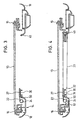
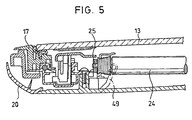
- a lid 13 is inserted, as shown in Fig. 3, 4 and 5 in sectional view.
- the lid 13 is either a permanently installed or an openable lid, for example a lifting roof, a sunroof, a sliding roof or a spoiler roof.
- the lid 13 is made of a transparent or translucent material, such as glass or acrylic glass.
- a rectangular frame assembly 14 which is fixedly connected to the inside of the vehicle roof 11 and based on the direction of travel of the vehicle 10 includes a front frame member 15 and a rear frame member 16, as shown in FIG. 3 and 4 shown.
- the frame assembly 14 includes integral with the front and rear frame members 15, 16 connected side frame parts, of which in Fig. 5 with respect to the direction of travel left side frame member 17 is shown.
- the frame assembly 14 is formed as Profiltewil of sheet metal or plastic and covered in the direction of the interior of the passenger compartment by parts of the vehicle headlining or facing parts 18, 19 and 20 down.
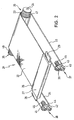
- roller blind device 21 In the frame assembly 14, lying below the lid 13, a roller blind device 21 according to the invention is used, which in the non-installed state in Fig. 2 and in the installed state in Figs. 3, 4 and 5 is shown.
- the roller blind device 21 comprises a roller blind 22 made of opaque or partially opaque material, such as fabric or plastic, and serves as a sunscreen for the covered by the transparent or translucent cover 13 roof opening 12.
- the blind sheet 22 with an end edge 23, hereinafter referred to as rear end edge, fixedly connected to a reel spool 24 which is preferably rotatably mounted on the rear transverse edge of the roof opening 12 adjacent to the rear frame member 16 in the lateral frame parts thereof, namely by laterally projecting from the reel spool 24, fixedly connected to this bearing pin 25, which are aligned with the longitudinal center axis of the reel spool 24.
- the roller blind device 21 comprises at its other end edge 26, which is hereinafter referred to as the front end edge, a Wernergel 27 with a flat rectangular handle bar from which laterally guide shoes 28, 29 project, which are preferably guided in guide rails, not shown, in the side frame members of the frame assembly 14 are provided.
- a Switzerlandspriegel 27 with a flat rectangular handle bar from which laterally guide shoes 28, 29 project, which are preferably guided in guide rails, not shown, in the side frame members of the frame assembly 14 are provided.
- the Switzerlandspriegel 27 comprises at its lower side a recessed grip 30, which is limited relative to the direction of travel of the vehicle 10 by front and rear strip-like projections 31, 32, whose function is explained below together with that of the recessed grip and the handle.
- the two belonging to the blind device 21 ropes 33 and 34, which are referred to below as, based on the direction of travel of the vehicle 10, left cable 33 and right cable 34.
- the ropes 33, 34 are connected at their front end fixed to the Werspriegel 27, in the illustrated embodiment with the guide shoes 28, 29, while the rear end of the ropes 33, 34 with the lateral outer ends 35, 36 of the reel spool 24 is firmly connected hereinafter referred to as left outer end 35 and right outer end 36, respectively.
- the ropes 33, 34 are guided over deflection devices 37, 38, which are referred to below as the left-hand deflection device 37 and the right-hand deflection device 38, respectively.
- the deflection devices 37, 38 each comprise two rollers 39, 40 and 41, 42, which are arranged one above the other, but are rotatably mounted out of contact with each other on the front frame part 15 about axes of rotation parallel to each other, which run parallel to the longitudinal center axis of the winding coil 24 ,
- each pair of rollers 39, 40 and 41, 42 rotatably mounted on a bearing block 43 and 44, which in turn with the front Frame member 15 is fixedly connected via a compression spring 45 and 46, respectively.
- the compression springs 45, 46 ensure that the composite of roller blind 22 and ropes 33, 34 is always held under tension, so that the roller blind 22 is as tense in any position as the ropes 33, 34.
- the compression springs 45, 46 can also be replaced by tension springs, which are to be positioned at the outer end in contrast to the compression springs, which are arranged at the inboard end of the deflection.
- An alternative to the compression springs 45, 46 which are fixedly arranged between the bearing blocks 43, 44 and the front frame part 15 can basically be tension springs or elastic sections of the same effect in the ropes 33, 34, to which Purpose these ropes are interrupted and firmly connected to the tension springs.
- the peculiarity of the roller blind device 21 shown in FIGS. 2 to 5 relates to the formation of the left and right outer ends 35, 36 of the reel spool 24 for the common winding and unwinding of the cable 33 and 34th Since the ropes 33, 34 wound on the same take-up and are unwound from this, as the roller blind 22, namely on or from the reel spool 24, and since the roller blind winding on the reel spool 24 in the course of winding is thicker and thinner in the course of unwinding, which related to a revolution of the reel spool 24 to a faster or slower winding of the roller blind 22 leads, it is advisable to maintain the tension on the composite of roller blind and ropes 33, 34, this speed gradient on the up / unwinding of the ropes 33, 34 to transmit.
- the winding coil outer ends 35, 36 taper conically outwards and on its outer circumference have a spiral winding groove 47 and 48, the diameter of which increases from outside to inside.
- the ropes 33, 34 are fixed inside the winding coil outer ends 35, 36, ie in the region of the largest diameter of the spiral winding grooves 47, 48.
- the pitch of the spiral winding grooves 47, 48 is an image of the varying roller blind winding on the winding spool 24, to always maintain the above-mentioned tension of the composite of roller blind 22 and ropes 33, 34.
- the left and right ropes 33, 34 are complete on the left and right winding coil outer ends 35, 36, from the inside to the outside, wound up; ie, in this state, the ropes 33, 34 emerge from the smallest diameter outer end of the spiral winding grooves 47, 48 from these grooves. If, on the other hand, the roller blind 22 is completely wound onto the reel spool 24 and the roller blind reel assumes its greatest outside diameter, the cables 33, 34 are completely unwound from the reel spool outer ends 35, 36 and the cables 33, 34 emerge from the largest in diameter Ends of the winding grooves 47, 48 from these grooves.
- roller blind device 21 A substantial advantage, which is achieved by the roller blind device 21 according to the invention, is that the composite of roller blind 22 and ropes 33, 34 is always in equilibrium of forces and thus stops at the point in which an operator controls this arrangement by means of the draw bar 27 or which has positioned in this trained recessed grip 30.
- stops in the form of stops 49, 50 are provided for determining the end positions of the Switzerlandspriegels in the region of the front or rear frame member 15 and 16 and at the front or rear transverse edge of the roof opening , which are preferably formed by the edges of the inner lining and engage with the grip recesses 31 and 32.
- the free ends of the stop bars 49, 50, which are intended to stop for the handle strip projections 31, 32 are related to a "soft" stop with an elastomer.
- Fener may alternatively be provided to the arrangement of the two rollers 39, 40 and 41, 42) of the deflection means 37 and 38 one above the other an arrangement of the rollers side by side or the use of a single guide roller.
- roller blind device 21 in the illustrated manual operating form due to the always present balance of forces between roller blind 22 and ropes 33 and 34 allows comfortable operation
- the same roller blind device 21 in an even more comfortable variant and advantageously by means of an electric drive 51 can be driven, the - indicated in Fig. 4 - is arranged in the region of the winding coil 24 and this drives.
- ropes for the purpose of the invention also includes tapes, threads, cables, cords or other elongated, windable traction elements.
Landscapes
- Engineering & Computer Science (AREA)
- Mechanical Engineering (AREA)
- Operating, Guiding And Securing Of Roll- Type Closing Members (AREA)
Claims (9)
- Pare-soleil pour un toit (11) de véhicule, comprenant un capot (13) transparent ou translucide affecté à une ouverture (12) du toit, et un dispositif (21) à store enroulable, placé au-dessous du capot (13) et muni d'un store (22) dont l'un (23) des bords extrêmes est fixé à un enrouleur (24) qui est disposé dans la région d'un bord transversal de l'ouverture (12) du toit, et sur lequel le store (22) peut être enroulé, sachant que des filins (33, 34), fixés aux extrémités extérieures latérales de l'autre bord extrême (26) du store (22), sont guidés vers l'enrouleur (24) autour d'un système de renvoi (37, 38) installé dans la région de l'autre bord transversal de l'ouverture (12) du toit, et sachant qu'un système (45, 46) est prévu pour imposer, dans la direction d'enroulement, une tension à l'assemblage constitué du store (22) et des filins (33, 34), caractérisé par le fait que les filins (33, 34) sont fixés aux extrémités extérieures latérales (35, 36) de l'enrouleur (24), et peuvent être enroulés sur ce dernier ; et par le fait que lesdites extrémités extérieures latérales (35, 36) dudit enrouleur (24) s'achèvent avec rétrécissement tronconique et sont pourvues, respectivement, d'une rainure spiroïdale d'enroulement (47, 48) destinée au filin respectif (33, 34), lequel est relié rigidement au segment tronconique intérieur, de diamètre maximal, de l'extrémité extérieure considérée (35, 36) de l'arbre enrouleur.
- Pare-soleil selon la revendication 1, caractérisé par le fait que le système de renvoi (37, 38) comporte, pour chaque filin (33, 34), au moins un rouleau de renvoi (39, 42) autour duquel ledit filin (33, 34) est guidé.
- Pare-soleil selon la revendication 1 ou 2, caractérisé par le fait que le système de tension comprend au moins un ressort (45, 46) pour chaque filin (33, 34).
- Pare-soleil selon la revendication 3, caractérisé par le fait que le ressort (45, 46) impose indirectement une tension au filin (33, 34), par l'intermédiaire du système de renvoi (37, 38).
- Pare-soleil selon l'une des revendications précédentes, caractérisé par le fait que l'extrémité du store (22), reliée aux filins (33, 34), comporte une planchette de traction (27) en vue de l'actionnement manuel dudit store (22).
- Pare-soleil selon la revendication 5, caractérisé par le fait qu'un listel de préhension, muni d'une augette de préhension (30) ouverte vers le bas, est façonné sur la planchette de traction (27).
- Pare-soleil selon la revendication 5 ou 6, caractérisé par le fait que la planchette de traction (27) comporte des patins de guidage (28, 29) qui font saillie latéralement et sont guidés, dans des glissières de guidage, dans la région des bords latéraux de l'ouverture (12) du toit.
- Pare-soleil selon l'une des revendications 5 à 7, caractérisé par le fait que des taquets (49, 50), dédiés à la planchette de traction (27), sont prévus sur les bords transversaux de l'ouverture (12) du toit.
- Pare-soleil selon l'une des revendications 1 à 8, caractérisé par le fait qu'un entraînement électrique (51) est prévu pour l'enrouleur (24).
Applications Claiming Priority (2)
| Application Number | Priority Date | Filing Date | Title |
|---|---|---|---|
| DE19910830 | 1999-03-11 | ||
| DE1999110830 DE19910830C1 (de) | 1999-03-11 | 1999-03-11 | Rollo-Sonnenschutz für ein Fahrzeugdach |
Publications (3)
| Publication Number | Publication Date |
|---|---|
| EP1034954A2 EP1034954A2 (fr) | 2000-09-13 |
| EP1034954A3 EP1034954A3 (fr) | 2001-07-11 |
| EP1034954B1 true EP1034954B1 (fr) | 2006-02-15 |
Family
ID=7900589
Family Applications (1)
| Application Number | Title | Priority Date | Filing Date |
|---|---|---|---|
| EP20000104701 Expired - Lifetime EP1034954B1 (fr) | 1999-03-11 | 2000-03-03 | Store pare-soleil à enrouler pour toit de véhicule |
Country Status (3)
| Country | Link |
|---|---|
| EP (1) | EP1034954B1 (fr) |
| JP (1) | JP2000272341A (fr) |
| DE (2) | DE19910830C1 (fr) |
Cited By (2)
| Publication number | Priority date | Publication date | Assignee | Title |
|---|---|---|---|---|
| DE102014209578A1 (de) | 2014-05-20 | 2015-11-26 | Ford Global Technologies, Llc | Sonnenschutzblende für einen lichtdurchlässigen Bereich eines Fahrzeugdachs |
| WO2023143993A1 (fr) * | 2022-01-25 | 2023-08-03 | Stobag Ag | Dispositif d'occultation et tissu pour un dispositif d'occultation |
Families Citing this family (44)
| Publication number | Priority date | Publication date | Assignee | Title |
|---|---|---|---|---|
| NL1015855C1 (nl) * | 2000-08-02 | 2000-11-13 | Inalfa Ind Bv | Zonnescherm. |
| DE10064718C1 (de) * | 2000-12-22 | 2002-03-21 | Webasto Vehicle Sys Int Gmbh | Rollo zum Verschließen einer Fenster- oder Dachöffnung |
| DE10101491C1 (de) * | 2001-01-12 | 2002-05-08 | Cts Fahrzeug Dachsysteme Gmbh | Rollo für ein durchsichtiges Dachteil in einem Fahrzeugdach |
| DE10110013C2 (de) * | 2001-03-01 | 2003-06-26 | Webasto Vehicle Sys Int Gmbh | Öffnungsfähiges Fahrzeugdach mit zwei transparenten Deckeln |
| DE10155167B4 (de) * | 2001-11-12 | 2005-09-29 | Webasto Ag | Sonnenschutz-Rollanordnung für ein Fahrzeugdach |
| DE10158428B4 (de) * | 2001-11-29 | 2005-09-22 | Webasto Ag | Rolloanordnung |
| DE10206161B4 (de) * | 2002-02-14 | 2005-06-02 | Webasto Ag | Öffnungsfähiges Fahrzeugdach mit mindestens einem Deckel und zwei Abdeckeinrichtungen |
| FR2841185A1 (fr) * | 2002-06-25 | 2003-12-26 | Wagon Automotive Snc | Store a enrouleur a entrainement par cable, et vehicule automobile correspondant |
| EP1566296A1 (fr) * | 2004-02-23 | 2005-08-24 | Grupo Antolin-Ingenieria, S.A. | Dispositif de protection solaire pour véhicules |
| DE102004038756A1 (de) * | 2004-08-09 | 2006-02-23 | Bos Gmbh & Co. Kg | Sonnenschutzrollo für Glasdächer |
| DE102004049167A1 (de) † | 2004-10-08 | 2006-04-20 | Hs Products Engineering Gmbh | Fensterrollo für ein Fahrzeugfenster |
| FR2878558B1 (fr) * | 2004-12-01 | 2008-09-12 | Webasto Systemes Carrosserie Ste | Dispositif d'occultation multi position notamment pour vehicule automobile |
| JP4732802B2 (ja) * | 2005-05-31 | 2011-07-27 | 芦森工業株式会社 | 車両用サンシェード装置 |
| DE102005048207B3 (de) * | 2005-10-07 | 2006-11-23 | Webasto Ag | Rolloanordnung für ein Kraftfahrzeug |
| FR2897634B1 (fr) * | 2006-02-22 | 2008-05-09 | Webasto Systemes Carrosserie S | Dispositif d'occultation a rideau pour panneau transparent notamment de vehicule automobile |
| DE102006035632B4 (de) * | 2006-07-31 | 2012-08-02 | Webasto Ag | Rolloanordnung für ein Fahrzeugdach |
| DE102006047348A1 (de) | 2006-09-29 | 2008-04-03 | Brose Fahrzeugteile Gmbh & Co. Kommanditgesellschaft, Coburg | Antriebsvorrichtung zum Bewegen eines Abdeckelementes, Türbaugruppe und Verfahren zur Montage der Antriebsvorrichtung |
| EP1964701B1 (fr) | 2007-02-27 | 2009-09-02 | Webasto AG | Dispositif abat-jour pour un véhicule automobile |
| JP4930168B2 (ja) * | 2007-04-17 | 2012-05-16 | トヨタ紡織株式会社 | サンシェード装置 |
| DE102007040282C9 (de) † | 2007-08-24 | 2016-03-10 | Küster Holding GmbH | Abdeckeinrichtung für den Fahrzeuginnenraum |
| JP4724221B2 (ja) * | 2008-12-12 | 2011-07-13 | 八千代工業株式会社 | ロールサンシェード装置 |
| DE102009013325A1 (de) * | 2009-03-19 | 2010-09-23 | Tesa Se | Vertikal sowie horizontal verbaubares Rollosystem, insbesondere Insektenschutzgitter-Rollosystem, mit geringer Bautiefe |
| DE102009016390A1 (de) * | 2009-04-07 | 2010-10-21 | Tesa Se | Flexibel verbaubares Rollosystem, insbesondere Insektenschutzgitter-Rollosystem, mit geringer Bautiefe |
| DE102009018246B4 (de) * | 2009-04-21 | 2021-07-08 | Dr. Ing. H.C. F. Porsche Aktiengesellschaft | Windschott für ein Cabriolet |
| FR2948322B1 (fr) * | 2009-07-21 | 2011-06-24 | Peugeot Citroen Automobiles Sa | Dispositif d'occultation pour une vitre non rectangulaire |
| JP5391165B2 (ja) | 2009-09-24 | 2014-01-15 | 八千代工業株式会社 | 車両のロールシェード装置 |
| JP5060576B2 (ja) * | 2010-03-26 | 2012-10-31 | 八千代工業株式会社 | 車両のロールシェード装置 |
| JP5884281B2 (ja) | 2010-11-05 | 2016-03-15 | アイシン精機株式会社 | 車両用サンシェード |
| KR101243359B1 (ko) * | 2010-11-22 | 2013-03-13 | 한국생산기술연구원 | 핸들샤프트가 구비된 자동차용 롤러 블라인드 |
| JP2013252837A (ja) | 2012-06-08 | 2013-12-19 | Aisin Seiki Co Ltd | サンシェード装置 |
| CN103352653B (zh) * | 2013-06-24 | 2015-05-06 | 宁波先锋新材料股份有限公司 | 一种同步带牵引的抗风遮阳卷帘 |
| DE102014225895A1 (de) * | 2014-12-15 | 2016-06-16 | Bos Gmbh & Co. Kg | Schutzvorrichtung für einen Fahrzeuginnenraum |
| CN104442299B (zh) * | 2014-12-26 | 2016-08-24 | 上海万超汽车天窗有限公司 | 遮阳帘导向限位支架 |
| DE102015106528A1 (de) | 2015-04-28 | 2016-11-03 | Lisa Dräxlmaier GmbH | Fahrzeugscheibenbeschattung mit Seilzugkonzept und Antrieb des Seilzugs über Zahnriemen |
| KR102288752B1 (ko) * | 2015-07-13 | 2021-08-11 | 현대모비스 주식회사 | 파노라마 루프용 에어백 장치 |
| DE102017211577A1 (de) * | 2017-07-06 | 2019-01-10 | Röchling Automotive SE & Co. KG | Kfz-Kühlmittel-Wärmetauscher mit wickelbarer Abdeckung mit veränderlicher Wicklungsgeschwindigkeit und daran angepasstem Zugmittel |
| DE102018206046A1 (de) * | 2018-04-20 | 2019-10-24 | Hs Products Engineering Gmbh | Rollovorrichtung für ein fahrzeugfenster |
| KR102872954B1 (ko) * | 2020-07-09 | 2025-10-17 | 현대자동차주식회사 | 차량용 전동커튼 장치 |
| US20250129610A1 (en) * | 2023-10-20 | 2025-04-24 | T & C Enterprises, LLC | Rolling protective cover |
| US20250353360A1 (en) * | 2024-05-17 | 2025-11-20 | Sergio Martinez-Armendariz | Automated sunshade systems and methods |
| CN222346734U (zh) * | 2024-05-27 | 2025-01-14 | 比亚迪股份有限公司 | 一种天窗遮阳帘结构及车辆 |
| EP4686589A1 (fr) * | 2024-08-02 | 2026-02-04 | Inalfa Roof Systems Group B.V. | Ensemble store à rouleau à entraînement direct |
| EP4686591A1 (fr) * | 2024-08-02 | 2026-02-04 | Inalfa Roof Systems Group B.V. | Ensemble store à rouleau à entraînement direct |
| EP4686590A1 (fr) * | 2024-08-02 | 2026-02-04 | Inalfa Roof Systems Group B.V. | Ensemble store à rouleau à entraînement direct |
Family Cites Families (6)
| Publication number | Priority date | Publication date | Assignee | Title |
|---|---|---|---|---|
| FR2581378B1 (fr) * | 1985-05-02 | 1988-04-15 | Bourdeau Michel | Dispositif de tension progressive d'un element souple enroulable |
| DE4105865C2 (de) * | 1991-02-25 | 1997-06-05 | Reinhard Bohnert | Vorrichtung zum Auf- und Abwickeln von Behängen, insbesondere Markisenstoffen, Rolläden, Gittern oder dergleichen |
| GB9319430D0 (en) * | 1993-09-21 | 1993-11-03 | Mirle Int Ltd | Sun blind |
| DE4337311C1 (de) * | 1993-11-02 | 1995-04-20 | Daimler Benz Ag | Sonnenschutz für eine Scheibe |
| DE19538551C1 (de) * | 1995-10-17 | 1996-10-24 | Webasto Systemkomponenten Gmbh | Sonnenschutz für ein Fahrzeugdach |
| DE19745866C1 (de) * | 1997-10-16 | 1998-12-24 | Webasto Karosseriesysteme | Rolloanordnung |
-
1999
- 1999-03-11 DE DE1999110830 patent/DE19910830C1/de not_active Expired - Fee Related
-
2000
- 2000-03-03 DE DE50012210T patent/DE50012210D1/de not_active Expired - Fee Related
- 2000-03-03 EP EP20000104701 patent/EP1034954B1/fr not_active Expired - Lifetime
- 2000-03-07 JP JP2000062252A patent/JP2000272341A/ja active Pending
Cited By (2)
| Publication number | Priority date | Publication date | Assignee | Title |
|---|---|---|---|---|
| DE102014209578A1 (de) | 2014-05-20 | 2015-11-26 | Ford Global Technologies, Llc | Sonnenschutzblende für einen lichtdurchlässigen Bereich eines Fahrzeugdachs |
| WO2023143993A1 (fr) * | 2022-01-25 | 2023-08-03 | Stobag Ag | Dispositif d'occultation et tissu pour un dispositif d'occultation |
Also Published As
| Publication number | Publication date |
|---|---|
| EP1034954A3 (fr) | 2001-07-11 |
| JP2000272341A (ja) | 2000-10-03 |
| DE19910830C1 (de) | 2000-06-29 |
| EP1034954A2 (fr) | 2000-09-13 |
| DE50012210D1 (de) | 2006-04-20 |
Similar Documents
| Publication | Publication Date | Title |
|---|---|---|
| DE19910830C1 (de) | Rollo-Sonnenschutz für ein Fahrzeugdach | |
| EP1258378B1 (fr) | Store enroulable pour élément de toit transparent | |
| EP1006012B1 (fr) | Store enroulable pour véhicle | |
| EP1010559B1 (fr) | Store roulant pour véhicule automobile | |
| DE2341328C3 (de) | Rolltor | |
| EP1495888A1 (fr) | Pare-soleil pour toit de véhicule | |
| DE19834777C2 (de) | Rollo, insbesondere Sonnenschutzrollo für die transparente Dachscheibe eines Kraftfahrzeugs | |
| WO2001053647A1 (fr) | Plaque de verre isolante comportant un systeme de store integre | |
| EP1794012A1 (fr) | Systeme de store pour vehicule automobile | |
| EP1367207A2 (fr) | Dispositif d'entraínement en particulier pour toit coulissant de véhicule, ainsi que toit coulissant de véhicule | |
| DE3345503A1 (de) | Rollo fuer fahrzeugscheiben | |
| DE10253816B3 (de) | Rollovorrichtung für ein Fahrzeug | |
| EP1626152A1 (fr) | Protection solaire pour un toit vitré | |
| DE19803129B4 (de) | Sonnenrollo für Kraftfahrzeug-Heckfenster | |
| DE10225360C1 (de) | Rollo mit seitlicher Führung | |
| DE102015106528A1 (de) | Fahrzeugscheibenbeschattung mit Seilzugkonzept und Antrieb des Seilzugs über Zahnriemen | |
| DE102006035632B4 (de) | Rolloanordnung für ein Fahrzeugdach | |
| DE102008011505B4 (de) | Rollosystem für ein Fahrzeug | |
| DE10322709B3 (de) | Sonnenschutzrolloanordnung für ein Fahrzeugdach sowie Fahrzeugdach mit einer solchen Sonnenschutzrolloanordnung | |
| DE202005006415U1 (de) | Baugruppe mit einem Rollo | |
| DE102007039214A1 (de) | Sonnenschutzeinrichtung für insbesondere einen lichtdurchlässigen Dachbereich eines Fahrzeugs | |
| DE10215322A1 (de) | Sonnenschutzrollo für ein Fahrzeugfenster | |
| EP1736628B1 (fr) | Dispositif de guidage pour une porte coulissante | |
| DE102004005754A1 (de) | Fahrzeugdach mit einer Rolloanordnung | |
| DE10316785B4 (de) | Rollovorrichtung |
Legal Events
| Date | Code | Title | Description |
|---|---|---|---|
| PUAI | Public reference made under article 153(3) epc to a published international application that has entered the european phase |
Free format text: ORIGINAL CODE: 0009012 |
|
| AK | Designated contracting states |
Kind code of ref document: A2 Designated state(s): DE FR GB IT NL |
|
| AX | Request for extension of the european patent |
Free format text: AL;LT;LV;MK;RO;SI |
|
| PUAL | Search report despatched |
Free format text: ORIGINAL CODE: 0009013 |
|
| AK | Designated contracting states |
Kind code of ref document: A3 Designated state(s): AT BE CH CY DE DK ES FI FR GB GR IE IT LI LU MC NL PT SE |
|
| AX | Request for extension of the european patent |
Free format text: AL;LT;LV;MK;RO;SI |
|
| 17P | Request for examination filed |
Effective date: 20011207 |
|
| AKX | Designation fees paid |
Free format text: DE FR GB IT NL |
|
| 17Q | First examination report despatched |
Effective date: 20031030 |
|
| GRAP | Despatch of communication of intention to grant a patent |
Free format text: ORIGINAL CODE: EPIDOSNIGR1 |
|
| GRAS | Grant fee paid |
Free format text: ORIGINAL CODE: EPIDOSNIGR3 |
|
| GRAA | (expected) grant |
Free format text: ORIGINAL CODE: 0009210 |
|
| AK | Designated contracting states |
Kind code of ref document: B1 Designated state(s): DE FR GB IT NL |
|
| REG | Reference to a national code |
Ref country code: GB Ref legal event code: FG4D Free format text: NOT ENGLISH |
|
| GBT | Gb: translation of ep patent filed (gb section 77(6)(a)/1977) |
Effective date: 20060308 |
|
| REF | Corresponds to: |
Ref document number: 50012210 Country of ref document: DE Date of ref document: 20060420 Kind code of ref document: P |
|
| ET | Fr: translation filed | ||
| PLBE | No opposition filed within time limit |
Free format text: ORIGINAL CODE: 0009261 |
|
| STAA | Information on the status of an ep patent application or granted ep patent |
Free format text: STATUS: NO OPPOSITION FILED WITHIN TIME LIMIT |
|
| 26N | No opposition filed |
Effective date: 20061116 |
|
| PGFP | Annual fee paid to national office [announced via postgrant information from national office to epo] |
Ref country code: NL Payment date: 20090303 Year of fee payment: 10 |
|
| PGFP | Annual fee paid to national office [announced via postgrant information from national office to epo] |
Ref country code: GB Payment date: 20090225 Year of fee payment: 10 |
|
| PGFP | Annual fee paid to national office [announced via postgrant information from national office to epo] |
Ref country code: DE Payment date: 20090226 Year of fee payment: 10 Ref country code: IT Payment date: 20090317 Year of fee payment: 10 |
|
| PGFP | Annual fee paid to national office [announced via postgrant information from national office to epo] |
Ref country code: FR Payment date: 20090316 Year of fee payment: 10 |
|
| REG | Reference to a national code |
Ref country code: NL Ref legal event code: V1 Effective date: 20101001 |
|
| GBPC | Gb: european patent ceased through non-payment of renewal fee |
Effective date: 20100303 |
|
| REG | Reference to a national code |
Ref country code: FR Ref legal event code: ST Effective date: 20101130 |
|
| PG25 | Lapsed in a contracting state [announced via postgrant information from national office to epo] |
Ref country code: NL Free format text: LAPSE BECAUSE OF NON-PAYMENT OF DUE FEES Effective date: 20101001 Ref country code: FR Free format text: LAPSE BECAUSE OF NON-PAYMENT OF DUE FEES Effective date: 20100331 |
|
| PG25 | Lapsed in a contracting state [announced via postgrant information from national office to epo] |
Ref country code: DE Free format text: LAPSE BECAUSE OF NON-PAYMENT OF DUE FEES Effective date: 20101001 |
|
| PG25 | Lapsed in a contracting state [announced via postgrant information from national office to epo] |
Ref country code: IT Free format text: LAPSE BECAUSE OF NON-PAYMENT OF DUE FEES Effective date: 20100303 Ref country code: GB Free format text: LAPSE BECAUSE OF NON-PAYMENT OF DUE FEES Effective date: 20100303 |