EP1034960B1 - Verteilergetriebe mit hydraulischer Bereichsschaltung und adaptiver Kupplungssteuerung - Google Patents
Verteilergetriebe mit hydraulischer Bereichsschaltung und adaptiver Kupplungssteuerung Download PDFInfo
- Publication number
- EP1034960B1 EP1034960B1 EP00105045A EP00105045A EP1034960B1 EP 1034960 B1 EP1034960 B1 EP 1034960B1 EP 00105045 A EP00105045 A EP 00105045A EP 00105045 A EP00105045 A EP 00105045A EP 1034960 B1 EP1034960 B1 EP 1034960B1
- Authority
- EP
- European Patent Office
- Prior art keywords
- clutch
- range
- mode
- actuator
- power transfer
- Prior art date
- Legal status (The legal status is an assumption and is not a legal conclusion. Google has not performed a legal analysis and makes no representation as to the accuracy of the status listed.)
- Expired - Lifetime
Links
Images



Classifications
-
- B—PERFORMING OPERATIONS; TRANSPORTING
- B60—VEHICLES IN GENERAL
- B60K—ARRANGEMENT OR MOUNTING OF PROPULSION UNITS OR OF TRANSMISSIONS IN VEHICLES; ARRANGEMENT OR MOUNTING OF PLURAL DIVERSE PRIME-MOVERS IN VEHICLES; AUXILIARY DRIVES FOR VEHICLES; INSTRUMENTATION OR DASHBOARDS FOR VEHICLES; ARRANGEMENTS IN CONNECTION WITH COOLING, AIR INTAKE, GAS EXHAUST OR FUEL SUPPLY OF PROPULSION UNITS IN VEHICLES
- B60K17/00—Arrangement or mounting of transmissions in vehicles
- B60K17/34—Arrangement or mounting of transmissions in vehicles for driving both front and rear wheels, e.g. four wheel drive vehicles
- B60K17/344—Arrangement or mounting of transmissions in vehicles for driving both front and rear wheels, e.g. four wheel drive vehicles having a transfer gear
- B60K17/346—Arrangement or mounting of transmissions in vehicles for driving both front and rear wheels, e.g. four wheel drive vehicles having a transfer gear the transfer gear being a differential gear
- B60K17/3467—Arrangement or mounting of transmissions in vehicles for driving both front and rear wheels, e.g. four wheel drive vehicles having a transfer gear the transfer gear being a differential gear combined with a change speed gearing, e.g. range gear
-
- B—PERFORMING OPERATIONS; TRANSPORTING
- B60—VEHICLES IN GENERAL
- B60K—ARRANGEMENT OR MOUNTING OF PROPULSION UNITS OR OF TRANSMISSIONS IN VEHICLES; ARRANGEMENT OR MOUNTING OF PLURAL DIVERSE PRIME-MOVERS IN VEHICLES; AUXILIARY DRIVES FOR VEHICLES; INSTRUMENTATION OR DASHBOARDS FOR VEHICLES; ARRANGEMENTS IN CONNECTION WITH COOLING, AIR INTAKE, GAS EXHAUST OR FUEL SUPPLY OF PROPULSION UNITS IN VEHICLES
- B60K17/00—Arrangement or mounting of transmissions in vehicles
- B60K17/34—Arrangement or mounting of transmissions in vehicles for driving both front and rear wheels, e.g. four wheel drive vehicles
- B60K17/348—Arrangement or mounting of transmissions in vehicles for driving both front and rear wheels, e.g. four wheel drive vehicles having differential means for driving one set of wheels, e.g. the front, at one speed and the other set, e.g. the rear, at a different speed
- B60K17/35—Arrangement or mounting of transmissions in vehicles for driving both front and rear wheels, e.g. four wheel drive vehicles having differential means for driving one set of wheels, e.g. the front, at one speed and the other set, e.g. the rear, at a different speed including arrangements for suppressing or influencing the power transfer, e.g. viscous clutches
-
- B—PERFORMING OPERATIONS; TRANSPORTING
- B60—VEHICLES IN GENERAL
- B60K—ARRANGEMENT OR MOUNTING OF PROPULSION UNITS OR OF TRANSMISSIONS IN VEHICLES; ARRANGEMENT OR MOUNTING OF PLURAL DIVERSE PRIME-MOVERS IN VEHICLES; AUXILIARY DRIVES FOR VEHICLES; INSTRUMENTATION OR DASHBOARDS FOR VEHICLES; ARRANGEMENTS IN CONNECTION WITH COOLING, AIR INTAKE, GAS EXHAUST OR FUEL SUPPLY OF PROPULSION UNITS IN VEHICLES
- B60K17/00—Arrangement or mounting of transmissions in vehicles
- B60K17/26—Arrangement or mounting of transmissions in vehicles characterised by arrangement, location, or type of freewheel device
-
- B—PERFORMING OPERATIONS; TRANSPORTING
- B60—VEHICLES IN GENERAL
- B60K—ARRANGEMENT OR MOUNTING OF PROPULSION UNITS OR OF TRANSMISSIONS IN VEHICLES; ARRANGEMENT OR MOUNTING OF PLURAL DIVERSE PRIME-MOVERS IN VEHICLES; AUXILIARY DRIVES FOR VEHICLES; INSTRUMENTATION OR DASHBOARDS FOR VEHICLES; ARRANGEMENTS IN CONNECTION WITH COOLING, AIR INTAKE, GAS EXHAUST OR FUEL SUPPLY OF PROPULSION UNITS IN VEHICLES
- B60K23/00—Arrangement or mounting of control devices for vehicle transmissions, or parts thereof, not otherwise provided for
- B60K23/08—Arrangement or mounting of control devices for vehicle transmissions, or parts thereof, not otherwise provided for for changing number of driven wheels, for switching from driving one axle to driving two or more axles
-
- B—PERFORMING OPERATIONS; TRANSPORTING
- B60—VEHICLES IN GENERAL
- B60K—ARRANGEMENT OR MOUNTING OF PROPULSION UNITS OR OF TRANSMISSIONS IN VEHICLES; ARRANGEMENT OR MOUNTING OF PLURAL DIVERSE PRIME-MOVERS IN VEHICLES; AUXILIARY DRIVES FOR VEHICLES; INSTRUMENTATION OR DASHBOARDS FOR VEHICLES; ARRANGEMENTS IN CONNECTION WITH COOLING, AIR INTAKE, GAS EXHAUST OR FUEL SUPPLY OF PROPULSION UNITS IN VEHICLES
- B60K23/00—Arrangement or mounting of control devices for vehicle transmissions, or parts thereof, not otherwise provided for
- B60K23/08—Arrangement or mounting of control devices for vehicle transmissions, or parts thereof, not otherwise provided for for changing number of driven wheels, for switching from driving one axle to driving two or more axles
- B60K23/0808—Arrangement or mounting of control devices for vehicle transmissions, or parts thereof, not otherwise provided for for changing number of driven wheels, for switching from driving one axle to driving two or more axles for varying torque distribution between driven axles, e.g. by transfer clutch
Definitions
- the present invention relates to a power transfer system for controlling the distribution of drive torque between the front and rear drivelines of a four-wheel drive vehicle,
- a transfer case is incorporated into the driveline and is normally operable in a two-wheel drive mode for delivering drive torque to the driven wheels.
- a "mode" shift mechanism can be selectively actuated by the vehicle operator for directly coupling the non-driven wheels to the driven wheels for establishing a part-time four-wheel drive mode.
- motor vehicles equipped with such part-time power transfer systems offer the vehicle operator the option of selectively shifting between the two-wheel drive mode during normal road conditions and the part-time four-wheel drive mode for operation under adverse road conditions.
- An example of a part-time transfer case is disclosed in commonly-owned U.S. Patent No. 4,770,280 to Frost.
- the "on-demand” feature is incorporated into the transfer case by replacing the mode shift mechanism with a clutch assembly that is interactively associated with an electronic control system and a sensor arrangement. During normal road conditions, the clutch assembly is maintained in a non-actuated condition such that drive torque is only delivered to the driven wheels. However, when the sensors detect a low traction condition at the driven wheels, the clutch assembly is automatically actuated to deliver drive torque "on-demand" to the non-driven wheels.
- the amount of drive torque transferred through the clutch assembly to the non-driven wheels can be varied as a function of specific vehicle dynamics, as detected by the sensor arrangement.
- One example of such an "on-demand" power transfer system is disclosed in commonly-owned U.S. Pat. No. 5,323,871 to Wilson et al wherein the electronically-controlled clutch assembly is operable for automatically controlling the amount of drive torque transferred to the non-driven wheels as a function of the wheel speed difference (i.e., the wheel slip) between the driven and non-driven wheels.
- full-time power transfer systems having a transfer case equipped with a center differential that functions to permit interaxle speed differentiation while transferring drive torque to both of the front and rear drivelines.
- full-time transfer cases are also equipped with a clutch assembly for limiting speed differentiation and biasing the torque transferred across the center differential.
- full-time transfer cases are disclosed in commonly-owned U.S. Patent No. 5,697,861 to Wilson and U.S. Patent No. 5,702,321 to Bakowski et al. which are respectively equipped with mechanically-actuated and hydraulically-actuated clutch assemblies for controllably modulating the drive torque delivered across the center differential to the front and rear drivelines.
- a power transfer system according to the preamble of claim 1 is known from US 4503927 A.
- this transfer system two seperate range actuators are used to operate the clutches of the range clutch assembly.
- a full-time power transfer system to include a transfer case having a clutch assembly arranged to control speed differentiation and torque biasing across an interaxle differential, a hydraulic clutch actuation system operable to control actuation of the clutch assembly, sensors for detecting and generating sensor signals indicative of various dynamic and operational characteristics of the vehicle, and a controller for controlling the hydraulic clutch actuation system in response to the sensor signals.
- the clutch assembly Upon the occurrence of traction loss, the clutch assembly is automatically actuated for limiting interaxle slip while transferring increased drive torque to the non-slipping driveline.
- the actuated condition of the clutch assembly is controllably modulated between its non-actuated and fully-actuated limits for automatically varying the magnitude of speed differentiation and torque biasing across the interaxle differential in response to changes in the dynamic and operational characteristics of the vehicle.
- the full-time power transfer system may further include means for establishing a locked four-wheel drive mode in addition to the full-time four-wheel drive mode.
- a mode select mechanism is provided for permitting the vehicle operator to select one of the full-time and locked four-wheel drive modes and generate a mode signal indicative thereof.
- the mode signal is delivered to the controller for use in controlling actuation of the clutch assembly.
- the clutch assembly is fully-actuated for preventing speed differentiation across the Interaxle differential and thereby delivering non-differentiated drive torque to the front and rear drivelines.
- the power transfer system of the present invention offers the vehicle operator the option of selecting the specific four-wheel drive mode best-suited for operating the motor vehicle during normal or adverse road conditions as well as for off-road use.
- an on-demand power transfer system for establishing an on-demand four-wheel drive mode and includes a transfer case having the clutch assembly arranged to automatically transfer drive torque from the primary output shaft to the secondary output shaft.
- the on-demand power transfer system can include a mode select mechanism for permitting selection of one of the on-demand four-wheel drive mode and a part-time four-wheel drive mode. When the part-time four-wheel drive mode is selected, the clutch assembly is fully-actuated for locking the secondary output shaft for common rotation with the primary output shaft.
- the transfer cases can be equipped with a gearset and a hydraulically-actuated range shift mechanism for permitting "on-the-move” shifting between high-range and low-range drive modes.
- the motor vehicle drivetrain includes a front driveline 12 and a rear driveline 14 both drivable from a source of power, such as an engine 16, through a transmission 18 which may be of either the manual or automatic type.
- the drivetrain includes a transfer case 20 for transmitting drive torque from engine 16 and transmission 18 to front driveline 12 and rear driveline 14.
- Front driveline 12 includes a pair of front wheels 22 connected at opposite ends of a front axle assembly 24 having a front differential 26 that is coupled to one end of a front drive shaft 28, the opposite end of which is coupled to a front output shaft 30 of transfer case 20.
- rear driveline 14 includes a pair of rear wheels 32 connected at opposite ends of a rear axle assembly 34 having a rear differential 36 coupled to one end of a rear drive shaft 38, the opposite end of which is interconnected to a rear output shaft 40 of transfer case 20.
- transfer case 20 is equipped with a two-speed planetary gearset 42, a range clutch assembly 44, an interaxle differential 46, and a mode clutch assembly 48.
- Range clutch assembly 44 is operable to couple components of planetary gearset 42 for driving an input member of interaxle differential 46 at either of a first (i.e., high-range) or second (i.e., low-range) speed ratio.
- mode clutch assembly 48 is operable to control the magnitude of speed differentiation and torque biasing between rear output shaft 40 and front output shaft 30.
- Power transfer system 10 further includes a power-operated clutch actuation system 50 for controlling actuation of range clutch assembly 44 and mode clutch assembly 48, a sensor group 52 for sensing specific dynamic and operational characteristics of the motor vehicle and generating sensor input signals indicative thereof, and a controller 54 for generating control signals in response to the sensor input signals.
- Power transfer system 10 also includes a mode select mechanism 56 for permitting the vehicle operator to select one of the available drive modes.
- controller 54 controls clutch actuation system 50 in response to a mode signal sent to controller 54 from mode select mechanism 52 that is indicative of the particular mode selected.
- controller 54 When an "adaptive" four-wheel drive mode is selected, controller 54 operates to continuously monitor and automatically regulate the actuated condition of mode clutch assembly 48 between its non-actuated and fully-actuated limits for varying the magnitude of speed differentiation and torque transfer between output shafts 30 and 40. However, when the mode signal indicates that a "locked" four-wheel drive mode has been selected, mode clutch assembly 48 is fully actuated, whereby non-differentiated power is delivered to output shafts 30 and 40. The locked four-wheel drive mode is provided for permitting improved traction when the motor vehicle is operated off-road or on severe road conditions,
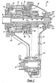
- Transfer case 20A includes a housing assembly 58 and an input shaft 60 rotatably supported from housing assembly 58.
- Input shaft 60 is adapted for connection to an output shaft (not shown) of transmission 18 such that both are rotatably driven by engine 16 of the motor vehicle.
- rear output shaft 40 is rotatably supported between input shaft 60 and housing assembly 58 while front output shaft 30 is rotatably supported from housing assembly 58.
- Planetary gearset 42 includes a first ring gear 64, a first sun gear 66 fixed for rotation with input shaft 60, and a set of first pinion gears 68 which are each rotatably supported on a pinion shaft 70 and meshed with first sun gear 66 and first ring gear 64.
- First ring gear 64 is axially constrained by thrust rings 71 relative to pinion gears 68.
- Each pinion shaft 70 extends between a front carrier ring 72 and a rear carrier ring 74 which are interconnected to define a planet carrier 76.
- a second ring gear 78 extends from rear carrier ring 74 of planet carrier 76 and acts as the input to interaxle differential 46.
- Planetary gearset 42 functions as a two-speed gear reduction unit which, in conjunction with range clutch assembly 44 is operable to establish first and second drive connections between input shaft 60 and second ring gear 78.
- first drive connection planet carrier 76 is coupled by range clutch assembly 44 for common rotation with input shaft 60.
- first drive connection defines a high-range drive mode in which second ring gear 78 is driven at a first (i.e., direct) speed ratio with respect to input shaft 60.
- the second drive connection is established by range clutch assembly 44 coupling first ring gear 64 to housing assembly 58.
- the second drive connection defines a low-range drive mode in which second ring gear 78 is driven at a second (i.e., reduced) speed ratio relative to input shaft 60.
- Interaxle differential 46 functions to permit speed differentiation and distribute drive torque between front output shaft 30 and rear output shaft 40 so as to establish a differentiated or "full-time" four-wheel drive mode.
- second ring gear 78 when driven at either of the first and second speed ratios, acts as the input to interaxle differential 46.
- Interaxle differential 46 also includes a planetary gearset with outputs operably coupled to front output shaft 30 and rear output shaft 40.
- this gearset includes a second sun gear 84 fixed for rotation with rear output shaft 40, a pinion carrier 86 coupled via a transfer mechanism 88 for rotation with front output shaft 30, a set of second pinions 90 rotatably supported from pinion carrier 86 and meshed with second sun gear 84, and a set of third pinions 92 rotatably supported from pinion carrier 86 and meshed with second ring gear 78.
- pinions 90 and 92 are arranged in meshed pairs and are supported on corresponding pinion posts 94 and 96 which extend between a front carrier plate 98 and a rear carrier plate 100 that are interconnected to define pinion carrier 86.
- Transfer mechanism 88 includes a drive sprocket 106 rotatably supported on rear output shaft 40 and which has a tubular hub segment 108 splined to rear carrier plate 100 of pinion carrier 86. Transfer mechanism 88 also includes a driven sprocket 110 fixed to front output shaft 30, and a power transfer device, such as chain 112, which interconnects driven sprocket 110 to drive sprocket 106.
- range clutch assembly 44 is shown to include a first clutch pack 114 that is operably mounted between a drum 116 fixed to first ring gear 64 and housing assembly 58.
- Clutch pack 114 includes a set of inner clutch plates 118 splined to drum 116 and which are alternately interleaved with a set of outer clutch plates 120 splined to housing assembly 58.
- Clutch pack 114 is shown to be located between a reaction plate 122 and a pressure plate 124, both of which are splined to housing assembly 58.
- a snap ring 126 is provided to axially restrain and locate reaction plate 122 relative to housing assembly 58.
- Range clutch assembly 44 is also shown to include a spring-biased cone clutch 128 that is operably mounted between front carrier ring 72 and input shaft 60.
- Cone clutch 128 includes an outer clutch ring 130 that is fixed for rotation with an annular hub segment 132 of front carrier ring 72.
- a snap ring 134 axially restrains outer clutch ring 130 against a shoulder portion of front carrier ring 72.
- Cone clutch 128 also includes an inner clutch ring 136 that is splined to input shaft 60.
- Outer clutch ring 130 has a tapered aperture defining a frusto-conical inner surface 138 that is adapted to mate with a frusto-conical outer surface 140 of inner clutch ring 136.
- a layer of friction material is bonded to one or both of conical surfaces 138 and 140, of the type used in synchronizer cones.
- Cone clutch 128 also includes a release spring 142 which is located between first sun gear 66 and a rear edge surface of inner clutch ring 136.
- range clutch assembly 44 includes a range piston 144 mounted in, and sealed relative to, a pressure chamber 146 formed in housing assembly 58. Range piston 144 is supported in pressure chamber 146 for axial movement relative to clutch pack 114 and cone clutch 128.
- Range piston 144 includes a first end segment 148 which acts on pressure plate 124 and a second end segment 150 which acts on a thrust bearing assembly 152. As seen, thrust bearing assembly 152 engages a front edge surface of inner clutch ring 136.
- Clutch actuation system 50 is schematically shown to include a pump 154 which draws fluid from a reservoir 156 for supplying high pressure fluid to the inlet of a first control valve 158.
- First control valve 158 is actuated by controller 54 for controlling the fluid pressure in pressure chamber 146 for causing movement of range piston 144 between a high-range position and a low-range position.
- controller 54 for controlling the fluid pressure in pressure chamber 146 for causing movement of range piston 144 between a high-range position and a low-range position.
- clutch pack 114 With range piston 144 in its high-range position, clutch pack 114 is released and cone clutch 128 is engaged.
- movement of range piston 144 to its low-range position causes clutch pack 114 to engage while cone clutch 128 is released.
- first control valve 158 is an electrically-actuated two-position valve that is operable in a first mode to interrupt fluid flow from pump 154 to pressure chamber 146 while permitting fluid to vent from pressure chamber 146 back to reservoir 156.
- release spring 142 forcibly urges inner clutch ring 136 to slide axially in a forward direction to a locked position whereat its outer cone surface 140 is in taper-locked engagement with inner cone surface 138 of outer clutch ring 130.
- This axial movement of inner clutch ring 136 causes corresponding forward movement of range piston 144 to its high-range position which, in turn, results in movement of first end segment 148 to a retracted position for releasing clutch pack 128.
- planet carrier 76 is coupled for rotation with first sun gear 66 via the taper-lock of cone clutch 128 while first ring gear 64 is free to rotate relative to housing assembly 58.
- first drive connection is established and second ring gear 78 is driven for common rotation with input shaft 60.
- Shifting of first control valve 158 into a second mode functions to interrupt communication between pressure chamber 146 and reservoir 156 while providing fluid communication from pump 154 to pressure chamber 146.
- first control valve 158 operating in its second mode, the increased fluid pressure in pressure chamber 146 causes range piston 144 to move from its high-range position to its low-range position which, in turn, causes inner clutch ring 136 to slide axially in a rearward direction from its locked position to a released position in opposition to the biasing of release spring 142.
- Such movement of inner clutch ring 136 causes its outer cone surface 140 to be released from taper-locked engagement with inner cone surface 138 of outer clutch ring 130, thereby uncoupling planet carrier 76 from first sun gear 66.
- range piston 144 moves to its low-range position to its low-range position.
- first end segment 148 moves from the retracted position to an extended position for compressing first clutch pack 128 and braking rotation of first ring gear 64.
- first ring gear 64 is held stationary and the second drive connection is established with planet carrier 76 driven at a reduced speed relative to input shaft 60.
- mode clutch assembly 48 is arranged for controlling speed differentiation and torque biasing between second ring gear 78 and pinion carrier 86 of interaxle differential 46.
- Mode clutch assembly 48 includes a multi-plate friction clutch having an outer drum 160 fixed for rotation with drive sprocket 106 and a second clutch pack 162 operably installed between outer drum 160 and second ring gear 78.
- outer drum 160 includes a cylindrical drum housing 164 that is fixed (i.e., welded) to a housing plate 166 which, in turn, is fixed (i.e., welded) to drive sprocket 106.
- Clutch pack 162 includes a set of inner clutch plates 168 splined to second ring gear 78 and which are alternately interleaved with a set of outer clutch plates 170 splined to drum housing 164.
- Clutch pack 162 is shown to be located between a reaction plate 172 splined to drum housing 164 and a pressure plate 174 journalled in drum housing 164.
- a snap ring 176 axially restrains and locates reaction plate 172 on drum housing 164. Movement of pressure plate 174 functions to vary the frictional compressive force exerted on clutch pack 162 for regulating speed differentiation and biasing the torque distribution between rear output shaft 40 and front output shaft 30.
- mode clutch assembly 48 is also shown to include a set of lever arms 180 disposed adjacent to housing plate 166, a lever return spring 182 engaging lever arms 180, and a set of thrust pins 184 retained in throughbores 186 formed in drive sprocket 106.
- Lever arms 180 are equidistant and are retained for pivotal movement in radial channels formed in drum plate 166.
- Throughbores 186 are equally-spaced in a circumferential arrangement and are aligned with the radial channels in drum plate 166.
- an annular rim projection on pressure plate 174 engages an upper front face surface of each lever arm 180 while a first end of each thrust pin 184 engages a lower rear face surface of a corresponding lever arm 180.
- axially sliding movement of thrust pins 184 in a forward direction from a fully retracted position to a fully extended position causes lever arms 180 to pivot, in opposition to the biasing of lever return spring 182, from a first position to a second position.
- pressure plate 174 exerts a predetermined minimum clutch engagement force on clutch pack 162.
- pressure plate 174 exerts a predetermined maximum clutch engagement force on clutch pack 162.
- Mode clutch assembly 48 also includes a mode piston 194 mounted in and sealed relative to a pressure chamber 196 formed in housing assembly 58, and a thrust bearing assembly 198. Thrust bearing assembly 198 is disposed between an end segment 200 of mode piston 194 and a second end of each thrust pin 184. Thus, axial movement of mode piston 194 causes corresponding axial movement of thrust pins 184 which, as noted, functions to pivot lever arms 180 for controlling the clutch engagement force applied to clutch pack 162.
- Clutch actuation system 50 includes a second control valve 202 which is operable under the control of controller 54 to regulate the fluid pressure in pressure chamber 196 for causing movement of mode piston 194 between a released position and a locked position.
- second control valve 202 is a variable flow control valve arranged between pump 154 and reservoir 156 for regulating the fluid pressure in pressure chamber 196 as a function of control signals sent by controller 54 and which are generated based on the mode and sensor input signals.
- pressure chamber 196 is vented to reservoir 156 and a piston return spring 204 urges mode piston 194 toward its released position.
- mode piston 194 With mode piston 194 in its released position, return spring 182 biases lever arms 180 to the first position and thrust pins 184 to the fully retracted position. As such, the minimum clutch engagement force is applied to clutch pack 162 and mode clutch assembly 48 is considered to be in a non-actuated condition such that a differentiated or "full-time" four-wheel drive mode is established.
- a maximum pressure control signal is sent to second control valve 202
- a maximum fluid pressure is supplied to pressure chamber 196 which causes mode piston 194 to move toward its locked position.
- mode piston 194 causes thrust pins 184 to move toward the fully extended position and lever arms 180 to move toward the second position.
- mode piston 194 in its locked position the maximum clutch engagement force is applied to clutch pack 162 and mode clutch assembly 48 is considered to be in a fully-actuated condition for establishing a non-differentiated or "locked" four-wheel drive mode.
- Transfer case 20A is operable to establish six distinct operative four-wheel drive modes including full-time four-wheel high-range and low-range drive modes, adaptive four-wheel high-range and low-range drive modes, and locked four-wheel high-range and low-range drive modes.
- the particular drive mode selected is established by the position of range piston 144 and mode piston 194.
- the vehicle operator selects one of the available drive modes via actuation of mode select mechanism 52 which, in turn, sends a corresponding mode signal to controller 54. Thereafter, controller 54 sends appropriate control signals to first control valve 158 and second control valve 202.
- range piston 144 is moved to its high-range position and mode piston 194 is moved to its released position.
- range piston 144 When the locked four-wheel high-range drive mode is selected, range piston 144 is moved to its high-range position while mode piston 194 is moved to its locked position. When the full-time four-wheel low-range drive mode is selected, range piston 144 is moved to its low-range position while mode piston 194 is moved to its released position. When the locked four-wheel low-range drive mode is selected, range piston 144 is moved to its low-range position while mode piston 194 is moved to its locked position.
- mode clutch assembly 48 is actively controlled for providing automatic control of speed differentiation and torque biasing between output shafts 30 and 40.
- the actuated state of second control valve 202 is continuously modulated to vary the location of mode piston 194 relative to clutch pack 162 in accordance with specific predefined relationships that are established based on the current value of the sensor input signals.
- the magnitude of the clutch engagement force applied to mode clutch pack 162 can be modulated in a manner that is independent of any deliberate action on the part of the vehicle operator.
- controller 54 is operable to regulate the control signals sent to second control valve 202 which, in turn, causes corresponding regulation of the fluid pressure in pressure chamber 196 for adjustably controlling the location of mode piston 194 between its released and locked positions.
- transfer case 20A has been disclosed to be capable of providing six different drive modes, it is contemplated that most vehicle applications would limit the number of available drive modes.
- mode select mechanism 52 could easily be adapted to permit selection of three drive modes, namely, the adaptive and locked four-wheel high-range drive modes and the locked four-wheel low-range drive mode.
- Mode select mechanism 52 can take the form of any mode selector device under the control of the vehicle operator and which functions to generate a mode signal indicative of the specific drive mode selected.
- the mode selector device may be an array of dash-mounted push button switches.
- the mode selector device may be a manually-operable shift lever sequentially movable between a plurality of positions corresponding to the available operational drive modes which, in conjunction with a suitable electrical switch arrangement, generates a mode signal indicating the particular drive mode selected.
- mode select mechanism 52 offers the vehicle operator the option of deliberately choosing between the various operative drive modes.
- Transfer case 20B is shown which is a modified version of transfer case 20A with interaxle differential 46 removed to define an "on-demand" power transfer system
- Transfer case 20B is operable to make available at least six different drive modes. These include a two-wheel high-range drive mode, an on-demand four-wheel high-range drive mode, a part-time high-range drive mode, a two-wheel low-range drive mode, an on-demand four-wheel low-range drive mode, and a part-time four-wheel low-range drive mode.
- rear carrier ring 74' of planet carrier 76 is shown fixed via a splined connection 224 to rear output shaft 40.
- drive torque is transferred from planetary gearset 42 to rear output shaft 40 to define the high-range and low-range modes while mode clutch assembly 48 is arranged to transfer drive torque from rear output shaft 40 to front output shaft 30 for establishing the available four-wheel drive modes.
- the two-wheel drive modes are established with mode piston 194 in its released position such that all drive torque is directed to rear output shaft 40.
- the part-time four-wheel drive modes are established with mode piston 194 in its locked position such that drive sprocket 106 is coupled to planet carrier 76 and the drive torque is split evenly between output shafts 30 and 40.
- mode clutch assembly 48 is actively controlled for automatically modulating the clutch engagement force exerted on second clutch pack 162 which functions to regulate the amount of drive torque that is transferred to front output shaft 30.
- the actuated state of mode clutch assembly 48 is controlled as a function of predefined relationships established based on the sensor input signals.
- range clutch assembly 226 which can be incorporated into either of full-time transfer case 20A or on-demand transfer case 20B in substitution for range clutch assembly 44.
- range clutch assembly 226 has many components common to range clutch assembly 44 except that cone clutch 128 has been replaced with a third clutch pack 228 that is mounted between front carrier ring 72 and input shaft 60.
- Clutch pack 228 includes a set of inner clutch plates 230 splined to input shaft 60 and which are interleaved with a set of outer clutch plates 232 splined to hub segment 132 of front carrier ring 72.
- Clutch pack 228 is shown to be located between a reaction plate 234 and an apply plate 236, both of which are splined to input shaft 60.
- a disc spring 238 is disposed between apply plate 236 and a retainer ring 240 which is mounted on input shaft 60 and axially located thereon by snap rings 242.
- Disc spring 238 is arranged such that its intermediate segment engages a flange 244 on retainer ring 240 while second end segment 150' of range piston 144 engages its outer peripheral edge and apply plate 236 engages its inner peripheral edge.
- clutch actuation system 50 is used to control actuation of range clutch assembly 226 with first control valve 158 again operating to control movement of range piston 144 between its high-range and low-range positions.
- first clutch pack 114 is released and third clutch pack 228 is engaged.
- disc spring 238 causes apply plate 236 to slide rearwardly to a locked position for applying a compressing clamping force on third clutch pack 228.
- planet carrier 76 is coupled for common rotation with input shaft 60 while first ring gear 64 is free to rotate relative to housing assembly 58 for establishing the high-range drive mode.
- range piston 144 to its low-range position functions to engage first clutch pack 114 and release third clutch pack 228.
- rearward movement of range piston 144 causes disc spring 238 to pivot at flange 244 for permitting apply plate 236 to slide in a forward direction to a released position whereat planet carrier 76 rotates freely relative to input shaft 60.
- such movement of range piston 144 to its low-range position functions to compress first clutch pack 114 and brake rotation of first ring gear 64.
- a range clutch assembly 246 is shown which can be integrated into either of full-time transfer case 20A or on-demand transfer case 20B in substitution for range clutch assemblies 44 and 226.
- an over-running type lock-up clutch 248 is shown mounted between hub segment 132 of front carrier ring 72 and input shaft 60.
- range piston 144 does not actuate lock-up clutch 248, but is only operable to actuate first clutch pack 114.
- first clutch pack 114 is released and lock-up clutch 248 is engaged.
- planet carrier 76 is coupled by lock-up clutch 248 for common rotation with input shaft 60 while first ring gear 64 is free to rotate relative to housing assembly 58 for establishing the high-range drive mode.
- movement of range piston 144 to its low-range position functions to engage first clutch pack 114 and release lock-up clutch 248, whereby the low-range drive mode is established.
- Lock-up clutch 248 can be of the sprag or roller type.
- range clutch assembly 250 which can be installed in either of full-time transfer case 20A or on-demand transfer case 20B.
- range clutch assembly 250 includes first clutch pack 114 and a spring-biased bi-directional roller clutch 252 that is operably mounted between front carrier ring 72 and input shaft 60.
- Roller clutch 252 includes an outer race 254, tapered rollers 256, and inner race 258.
- Outer race 254 is fixed for rotation with hub segment 132 of front carrier ring 72 and has a tapered aperture defining a frusto-conical inner surface 260.
- inner race 258 is splined to input shaft 60 and has a frusto-conical outer surface 262.
- Tapered rollers 256 are retained in a cage (not shown) that is fixed to outer race 254, with rollers 256 mating with inner conical surface 260 on outer race 254 and outer conical surface 262 on inner race 258.
- a release spring 142 is located between first sun gear 66 and a rear edge surface of inner race 258.
- second end segment 150 of range piston 140 acts on thrust bearing assembly 152 which, in turn, acts on a front edge surface of inner race 258.
- controller 54 actuates first control valve 158 to control the supply of fluid to pressure chamber 146 for controlling movement of range piston 140 between its high-range and low-range positions which, in turn, causes corresponding movement of inner race 258 between a locked position and a released position.
- range piston 140 moves to its high-range position to cause release spring 142 to forcibly urge inner race 258 to slide axially relative to input shaft 60 in a forward direction to its locked position whereat tapered rollers 256 are wedged (i.e., clamped) between tapered surfaces 260 and 262.
- This wedging action results in outer race 254 being frictionally coupled to inner race 258, whereby planet carrier 76 is coupled for rotation with input shaft 60.
- movement of range piston 140 to its low-range position causes inner race 258 to slide axially in a rearward direction to its released position in opposition to the biasing of release spring 142.
- spring-biased roller clutch 252 is operable to establish a releasable taper-lock coupling between carrier 76 and input shaft 60.
- a mode clutch assembly 270 which can be used with either of full-time transfer case 20A and on-demand transfer case 20B.
- a modified drive sprocket 106' is shown to now define a piston housing segment 272 which is splined to drum housing 164.
- An annular pressure chamber 274 is formed in piston housing segment 272.
- a mode piston 276 is mounted in pressure chamber 274 and is movable relative to second clutch pack 162 between a released position and a locked position.
- a piston return spring 278 urges mode piston 276 toward the released position whereat the minimum clutch engagement force is exerted on clutch pack 162.
- one or more flow paths are formed in drive sprocket 106' which communicate with pressure chamber 274 and which include a radial passage 280 and an axial passage 282.
- a manifold 284 is journalled and sealed relative to rear output shaft 40 and drive sprocket 106'.
- Manifold 284 includes an inlet passage 286 and a port 288 providing fluid communication between second control valve 202 and the flow paths in drive sprocket 106'.
- second control valve 202 regulates the position of mode piston 276 between its released and locked positions for modulating the actuated condition of second clutch pack 162.
- Clutch actuation system 50 can be arranged with pump 154 mounted within transfer case housing assembly 58 to draw fluid from an internal sump area defining reservoir 156 or, In the alternative, pump 154 and reservoir 156 can be located remote from the transfer case. In addition, separate pumps can be used to control independent actuation of the range and mode clutch assemblies.
- Sensor group 52 preferably includes sensors for detecting various vehicle operational characteristics including, for example, front shaft speed, rear shaft speed, vehicle speed, accelerator position, transmission gear position, and brake actuation. While any suitable control relationships can be established to automatically modulate actuation of the mode clutch assembly, it is contemplated that controller 54 regulates the fluid pressure delivered to pressure chambers 196 and 254 as a function of the magnitude of speed differentiation between front output shaft 30 and rear output shaft 40. In this regard, predetermined fluid pressure versus speed differential relationships can be programmed into controller 54 for automatically modulating the actuated condition of the mode clutch assembly.
Landscapes
- Engineering & Computer Science (AREA)
- Chemical & Material Sciences (AREA)
- Combustion & Propulsion (AREA)
- Transportation (AREA)
- Mechanical Engineering (AREA)
- Arrangement And Driving Of Transmission Devices (AREA)
- Arrangement And Mounting Of Devices That Control Transmission Of Motive Force (AREA)
- Control Of Transmission Device (AREA)
- Control Of Driving Devices And Active Controlling Of Vehicle (AREA)
Claims (17)
- Kraftübertragungssystem zur Verwendung in einem Fahrzeug mit Allradantrieb mit einer Kraftquelle (16) und einem ersten (38) und zweiten (28) Antriebsstrang, umfassend:dadurch gekennzeichnet, dass die Bereichskupplungsbaugruppe ferner einen Bereichsbetätiger (144) enthält, der in einer ersten Stellung betätigbar ist, um die erste Kupplung (114) zu lösen und die zweite Kupplung (128) zu sperren und ferner in einer zweiten Stellung betätigbar ist, um die erste Kupplung zu sperren und die zweite Kupplung zu lösen.ein Verteilergetriebe (20) mit einer Antriebswelle (60), die Antriebsdrehmoment von der Kraftquelle (16) aufnimmt, einer ersten Abtriebswelle (40), die mit dem ersten Antriebsstrang (38) verbunden ist, einer zweiten Abtriebswelle (30), die mit dem zweiten Antriebsstrang (28) verbunden ist, einem Zahnradsatz, der ein durch die Antriebswelle (60) angetriebenes erstes Rad (66), ein zweites Rad (64) und ein drittes Rad (68) umfasst, die drehbar auf einem Träger (76) montiert sind, der mit der ersten Abtriebswelle (40) verbunden ist, wobei das dritte Rad (68) mit dem ersten (66) und zweiten (64) Rad in Eingriff steht, einem Übertragungsmechanismus (88), der mit der zweiten Abtriebswelle (30) gekoppelt ist, einer Bereichskupplungsbaugruppe (44), die eine erste Kupplung (114), die zwischen einem feststehenden Element und dem zweiten Rad (64) angeordnet ist und eine zweite Kupplung (128) umfasst, die zwischen der Antriebswelle (60) und dem Träger (76) angeordnet ist, und einer Betriebsartkupplungsbaugruppe (48), die eine dritte Kupplung (162), die zwischen dem Träger (76) und dem Übertragungsmechanismus (88) angeordnet ist, und einen Betriebsartbetätiger umfasst, der in einer ersten Stellung betätigbar ist, um die dritte Kupplung (162) zu lösen, und ferner in einer zweiten Stellung betätigbar ist, um die dritte Kupplung zu sperren;und ein Steuersystem (50) zum Steuern einer koordinierten Bewegung der Bereichskupplungsbaugruppe und des Betriebsartbetätigers,
- Kraftübertragungssystem nach Anspruch 1, ferner umfassend Sensoren zum Erfassen von Betriebseigenschaften des Fahrzeugs und zum Erzeugen von Sensorsignalen als Antwort auf diese; und
einen Betriebsartwählmechanismus, der die Wahl eines bedarfsabhängigen Hochbereichs-Allradantriebs und eines zeitweisen Niedrigbereichs-Allradantriebs ermöglicht, wobei der Betriebsartwählmechanismus ein Betriebsartsignal erzeugt, das die bestimmte gewählte Betriebsart angibt;
wobei das Steuersystem betätigbar ist, um den Bereichsbetätiger und den Betriebsartbetätiger als Antwort auf die Sensor- und Betriebsartsignale zu bewegen, wobei das Steuersystem betätigbar ist, um den Bereichsbetätiger in seine erste Stellung zu bewegen und die Stellung des Betriebsartbetätigers zwischen seiner ersten und seiner zweiten Stellung als Funktion der Sensorsignale zu modulieren, wenn der bedarfsabhängige Hochbereichs-Allradantriebs gewählt ist, und das Steuersystem betätigbar ist, um den Bereichsbetätiger in seine zweite Stellung und den Betriebsartbetätiger in seine zweite Stellung zu bewegen, wenn der zeitweise Niedrigbereichs-Allradantriebs gewählt ist. - Kraftübertragungssystem nach Anspruch 2, wobei der Betriebsartwählmechanismus ferner die Wahl eines zeitweisen Hochbereichs-Allradantriebs erlaubt, so dass das Steuersystem die Bewegung des Bereichsbetätigers in seine erste Stellung und die Bewegung des Betriebsartbetätigers in seine zweite Stellung ermöglicht.
- Kraftübertragungssystem nach Anspruch 2 oder 3, wobei der Betriebsartwählmechanismus ferner die Wahl eines Hochbereichs-Zweiradantriebs erlaubt, so dass das Steuersystem die Bewegung des Bereichsbetätigers in seine erste Stellung und die Bewegung des Betriebsartbetätigers in seine erste Stellung ermöglicht.
- Kraftübertragungssystem nach einem der Ansprüche 2 bis 4, wobei die Sensoren eine Drehzahldifferenz zwischen der ersten und der zweiten Abtriebswelle bestimmen, und wobei das Steuersystem die Stellung des Betriebsartbetätigers als Antwort auf Veränderungen der Größe der Drehzahldifferenz moduliert.
- Kraftübertragungssystem nach einem der vorhergehenden Ansprüche, wobei der Bereichsbetätiger einen in einer Druckkammer angeordneten Bereichskolben enthält, wobei der Bereichskolben ein erstes Segment, das auf die erste Kupplung wirkt, und ein zweites Segment aufweist, das auf die zweite Kupplung wirkt, und wobei das Steuersystem eine Hydraulikfluidquelle, eine Pumpe, ein Steuerventil zum Steuern der Fluidströmung zwischen der Pumpe und der Druckkammer, und eine Steuerung enthält, welche die Betätigung des Steuerventils steuert, wobei das Steuerventil in einer ersten Betriebsart betätigbar ist, um Fluid aus der Druckkammer abzulassen, um eine Bewegung des Bereichskolbens in seine erste Stellung zu bewirken, und wobei das Steuerventil in einer zweiten Betriebsart betätigbar ist, um Hochdruckfluid von der Pumpe zur Druckkammer zu leiten, um den Bereichskolben in seine zweite Stellung zu bewegen.
- Kraftübertragungssystem nach einem der vorhergehenden Ansprüche, wobei das erste Zahnrad einen Sonnenrad, das zweite Zahnrad ein Tellerrad und das dritte Zahnrad ein Antriebskegelrad ist, das mit dem Sonnenrad und dem Tellerrad in Eingriff steht und drehbar an dem Träger gelagert ist, wobei der Bereichsbetätiger in seiner ersten Stellung betätigbar ist, um die erste Kupplung zu veranlassen, das Tellerrad für eine Drehung bezüglich des feststehenden Elements freizugeben, während die zweite Kupplung veranlasst wird, den Träger für eine Drehung mit der Antriebswelle zu sperren, und wobei der Bereichsbetätiger in seiner zweiten Stellung betätigbar ist, um die erste Kupplung zu veranlassen, das Tellerrad an dem feststehenden Element zu sperren, während die zweite Kupplung veranlasst wird, den Träger für eine Drehung bezüglich der Antriebswelle freizugeben.
- Kraftübertragungssystem nach Anspruch 7, wobei die erste Kupplung ein zwischen dem Tellerrad und dem feststehenden Element montiertes Kupplungspaket ist, und die zweite Kupplung eine Kegelkupplung mit einem ersten Kegelelement, das an dem Träger befestigt ist, und einem zweiten Kegelelement ist, das zur Gleitbewegung auf der Antriebswelle gelagert ist, und wobei der Bereichsbetätiger auf dem Kupplungspaket und dem zweiten Kegelelement derart wirkt, dass, wenn der Bereichsbetätiger in seine erste Stellung bewegt wird, das Kupplungspaket freigegeben wird und das zweite Kegelelement in Spanneingriff mit dem ersten Kegelelement bewegt wird, und dass, wenn der Bereichsbetätiger in seine zweite Stellung bewegt wird, dieser eine Klemmlast auf das Kupplungspaket ausübt, während das zweite Kegelelement aus dem Spanneingriff mit dem ersten Kegelelement bewegt wird.
- Kraftübertragungssystem nach Anspruch 8, wobei das erste Kegelelement eine innere kegelförmige Oberfläche hat, die dazu geeignet ist, mit der äußeren kegelförmigen Oberfläche des zweiten Kegeleelements zusammenzupassen, und wobei das zweite Kegelelement aus einer gesperrten Stellung in eine entsperrte Stellung auf eine Bewegung des Bereichsbetätigers aus seiner ersten Stellung in seine Stellung hin bewegbar ist, so dass die äußere kegelförmige Oberfläche des zweiten Kegelelements in Spanneingriff mit der inneren kegelförmigen Oberfläche des ersten Kegelelements steht, wenn das zweite Kegelelement in seiner gesperrten Stellung ist, und dass die äußere kegelförmige Oberfläche aus dem Spanneingriff mit der inneren kegelförmigen Oberfläche gelöst wird, wenn das zweite Kegelelement in seiner entsperrten Stellung ist.
- Kraftübertragungssystem nach Anspruch 7, wobei die erste Kupplung ein zwischen dem Tellerrad und dem feststehenden Element montiertes erstes Kupplungspaket ist, und die zweite Kupplung ein zwischen dem Träger und der Antriebswelle montiertes zweites Kupplungspaket ist, und wobei der Bereichsbetätiger einen Bereichskolben enthält, der ein erstes Segment, das in das erste Kupplungspaket eingreift, und ein zweites Segment aufweist, das in eine Tellerfeder eingreift, die derart in das zweite Kupplungspaket eingreift, dass, wenn der Bereichskolben in seiner ersten Stellung ist, das erste Kupplungspaket freigegeben wird und die Tellerfeder eine Klemmkraft auf das zweite Kupplungspaket ausübt, und dass, wenn der Bereichskolben in seiner zweiten Stellung ist, das erste Segment eine Klemmkraft auf das erste Kupplungspaket ausübt und das zweite Segment die Tellerfeder bewegt, um die Klemmkraft von dem zweiten Kupplungspaket zu lösen.
- Kraftübertragungssystem nach Anspruch 7, wobei die erste Kupplung ein Kupplungspaket ist, das mit dem Tellerrad und dem feststehenden Element verbunden ist, und die zweite Kupplung eine Freilaufkupplung ist, welche die Antriebswelle mit dem Träger verbindet.
- Kraftübertragungssystem nach einem der vorhergehenden Ansprüche, wobei der Übertragungsmechanismus ein drehbar auf der ersten Abtriebswelle gelagertes Antriebsrad, ein an der zweiten Abtriebswelle befestigtes Abtriebsrad, und eine Leistungsübertragungsvorrichtung umfasst, die das Abtriebsrad mit dem Antriebsrad koppelt, wobei die dritte Kupplung ein Kupplungspaket ist, das mit dem Träger und dem Antriebsrad verbunden ist, und wobei der Betriebsartbetätiger einen Betriebsartkolben enthält, der in einer in dem Antriebsrad gebildeten Druckkammer angeordnet ist und zwischen einer zurückgezogenen Stellung, bei der eine minimale Einkuppelkraft auf das Kupplungspaket ausgeübt wird, und einer ausgestreckten Stellung bewegbar ist, bei der eine maximale Einkuppelkraft auf das Kupplungspaket ausgeübt wird.
- Kraftübertragungssystem nach Anspruch 12, wobei das Steuersystem eine Hydraulikfluidquelle, eine Pumpe, ein Steuerventil zum Steuern der Fluidströmung zwischen der Pumpe und der Druckkammer, und eine Steuerung enthält, welche die Betätigung des Steuerventils steuert, wobei die Steuerung betätigbar ist, um den betätigten Zustand des Steuerventils zu modulieren, um den Betriebsartkolben zwischen seiner zurückgezogenen und seiner ausgestreckten Stellung zu bewegen, um die auf das Kupplungspaket als Funktion der Sensorsignale ausgeübte Einkuppelkraft zu modulieren.
- Kraftübertragungssystem nach einem der vorhergehenden Ansprüche, umfassend ein Zwischenachsdifferential mit einem durch den Träger angetriebenen Eingang, einem ersten, die erste Abtriebswelle antreibenden ersten Ausgang, und einem zweiten, den Übertragungsmechanismus antreibenden zweiten Ausgang.
- Kraftübertragungssystem nach Anspruch 14, wobei der Differentialeingang ein an dem Träger befestigtes zweites Tellerrad, der erste Ausgang ein an der ersten Abtriebswelle befestigtes zweites Sonnenrad, und der zweite Ausgang ein an dem Übertragungsmechanismus befestigter zweiter Träger ist, wobei der zweite Träger Antriebskegelräder lagert, die mit dem zweiten Tellerrad und dem zweiten Sonnenrad in Eingriff stehen, wobei der Betriebsartbetätiger in seiner ersten Stellung betätigbar ist, um die dritte Kupplung zu lösen, um eine Drehzahldifferenzierung zwischen dem zweiten Tellerrad und dem Übertragungsmechanismus zu ermöglichen, und der Betriebsartbetätiger ferner in seiner zweiten Stellung betätigbar ist, um die dritte Kupplung zu sperren, um eine Drehzahldifferenzierung zwischen diesen zu verhindern.
- Kraftübertragungssystem nach Anspruch 15, wobei der Übertragungsmechanismus ein drehbar auf der ersten Abtriebswelle gelagertes Antriebsrad, ein an der zweiten Abtriebswelle befestigtes Abtriebsrad, und eine Leistungsübertragungsvorrichtung umfasst, die das Abtriebsrad mit dem Antriebsrad koppelt, wobei die dritte Kupplung ein Kupplungspaket ist, das mit dem zweiten Tellerrad und dem Antriebsrad verbunden ist, und wobei der Betriebsartbetätiger einen Betriebsartkolben enthält, der in einer in dem Antriebsrad gebildeten Druckkammer angeordnet ist und zwischen einer zurückgezogenen Stellung, bei der eine minimale Einkuppelkraft auf das Kupplungspaket ausgeübt wird, und einer ausgestreckten Stellung bewegbar ist, bei der eine maximale Einkuppelkraft auf das Kupplungspaket ausgeübt wird.
- Kraftübertragungssystem nach Anspruch 16, wobei das Steuersystem eine Hydraulikfluidquelle, eine Pumpe, ein Steuerventil zum Steuern der Fluidströmung zu der Druckkammer hin, und eine Steuerung enthält, welche die Betätigung des Steuerventils steuert, wobei die Steuerung betätigbar ist, um den betätigten Zustand des Steuerventils zu modulieren, um den Betriebsartkolben zwischen seiner zurückgezogenen und seiner ausgestreckten Stellung zu bewegen, um die auf das Kupplungspaket als Funktion der Sensorsignale ausgeübte Einkuppelkraft zu modulieren.
Applications Claiming Priority (2)
| Application Number | Priority Date | Filing Date | Title |
|---|---|---|---|
| US12350299P | 1999-03-09 | 1999-03-09 | |
| US123502P | 1999-03-09 |
Publications (3)
| Publication Number | Publication Date |
|---|---|
| EP1034960A2 EP1034960A2 (de) | 2000-09-13 |
| EP1034960A3 EP1034960A3 (de) | 2002-01-16 |
| EP1034960B1 true EP1034960B1 (de) | 2003-12-17 |
Family
ID=22409051
Family Applications (1)
| Application Number | Title | Priority Date | Filing Date |
|---|---|---|---|
| EP00105045A Expired - Lifetime EP1034960B1 (de) | 1999-03-09 | 2000-03-09 | Verteilergetriebe mit hydraulischer Bereichsschaltung und adaptiver Kupplungssteuerung |
Country Status (4)
| Country | Link |
|---|---|
| US (2) | US6354977B1 (de) |
| EP (1) | EP1034960B1 (de) |
| AT (1) | ATE256572T1 (de) |
| DE (1) | DE60007200T2 (de) |
Families Citing this family (38)
| Publication number | Priority date | Publication date | Assignee | Title |
|---|---|---|---|---|
| US6446774B2 (en) * | 2000-04-10 | 2002-09-10 | New Venture Gear, Inc. | Active control of a hydra-mechanical traction control device |
| WO2002030698A1 (en) * | 2000-10-10 | 2002-04-18 | Terex Corporation | Two speed gear box |
| US6464608B2 (en) * | 2001-02-08 | 2002-10-15 | New Venture Gear Inc. | Transfer case for hybrid vehicle |
| US6612957B2 (en) | 2001-03-27 | 2003-09-02 | New Venture Gear, Inc. | Hydraulic shift transfer case with band brake and bi-directional clutch |
| US6602159B1 (en) * | 2002-02-05 | 2003-08-05 | New Venture Gear, Inc. | On-demand transfer case with integrated sprocket and bi-directional clutch assembly |
| US7172528B2 (en) * | 2003-03-28 | 2007-02-06 | Borgwarner Inc. | Transfer case with overdrive/underdrive shifting |
| DE10333652A1 (de) * | 2003-07-24 | 2005-02-24 | Bayerische Motoren Werke Ag | Steuervorrichtung für ein zumindest zeitweise vierradgetriebenes Kraftfahrzeug |
| US6997299B2 (en) * | 2003-07-28 | 2006-02-14 | Magna Powertrain, Inc. | Hydraulic clutch actuation system |
| US7294086B2 (en) * | 2003-07-28 | 2007-11-13 | Magna Powertrain, Usa, Inc. | Hydraulic control system for multiple clutches in a motor vehicle |
| US7021445B2 (en) * | 2003-07-28 | 2006-04-04 | Magna Powertrain, Inc. | Low power hydraulic clutch actuation systems |
| US7070036B2 (en) * | 2003-08-29 | 2006-07-04 | Muncie Power Products, Inc. | Power takeoff device |
| US20050101429A1 (en) * | 2003-11-12 | 2005-05-12 | Timothy Allen | Transfer case having high-range and low-range selection controlled through a coupler |
| US7743888B2 (en) * | 2003-11-12 | 2010-06-29 | Ford Global Technologies, Llc | Transmission and transfer case having integrated lubrication systems |
| US20050101431A1 (en) * | 2003-11-12 | 2005-05-12 | Timothy Allen | Multiple speed transfer case |
| US6994650B2 (en) * | 2003-11-12 | 2006-02-07 | Ford Global Technologies, Llc | Park brake mechanism for integrated transmission and transfer case |
| US20050116537A1 (en) * | 2003-12-01 | 2005-06-02 | Zalewski John D. | Combination braking and traction control system for a motor vehicle |
| US20050189190A1 (en) * | 2004-02-27 | 2005-09-01 | Kowalsky Christopher J. | Electrohydraulic clutch assembly |
| US20070137966A1 (en) * | 2004-02-27 | 2007-06-21 | Borgwarner Inc. | Electrohydraulic clutch assembly |
| US20050204838A1 (en) * | 2004-03-19 | 2005-09-22 | Degraffenreid Monica | Multi-speed automatic layshaft transfer case |
| US7178654B2 (en) * | 2004-09-01 | 2007-02-20 | Magna Powertrain Usa, Inc. | Low power modulating clutch control system |
| US7097019B2 (en) * | 2004-09-01 | 2006-08-29 | Magna Powertrain Usa, Inc. | Low power modulating clutch control system with electromagnetic actuator |
| US7182194B2 (en) * | 2004-09-01 | 2007-02-27 | Magna Powertrain Usa, Inc. | Low power modulating clutch control system with combination accumulator and piston actuator |
| US7506740B2 (en) * | 2004-09-01 | 2009-03-24 | Magna Powertrain Usa, Inc. | Power transmission device with clutch control system |
| US7588133B2 (en) * | 2004-09-01 | 2009-09-15 | Magna Powertrain Usa, Inc. | Clutch control system for power transmission devices |
| US7186199B1 (en) | 2004-10-29 | 2007-03-06 | Torque-Traction Technologies. Llc. | Torque vectoring gear drive apparatus |
| CA2670540C (en) * | 2006-11-30 | 2015-06-16 | Magna Powertrain Usa, Inc. | Torque limiting clutch assembly |
| US7837590B2 (en) * | 2007-03-12 | 2010-11-23 | Gm Global Technology Operations, Inc. | Transmission assembly |
| US8092334B2 (en) * | 2007-03-16 | 2012-01-10 | Gkn Driveline North America, Inc. | Two-stage two-speed front differential |
| US8958965B2 (en) * | 2007-09-13 | 2015-02-17 | Ford Global Technologies Llc | System and method for managing a powertrain in a vehicle |
| US8647225B2 (en) * | 2007-11-29 | 2014-02-11 | Ford Global Technologies, Llc | Transfer case for a motor vehicle powertrain |
| SE533000C2 (sv) * | 2008-10-14 | 2010-06-08 | Bae Systems Haegglunds Ab | Navreduktionsväxel för hjulfordon jämte drivlina för sådant fordon samt fleraxligt hjulfordon utrustat med sådan drivlina |
| US8235198B2 (en) | 2008-11-20 | 2012-08-07 | Borgwarner, Inc. | Hydraulic clutch assembly for a motor vehicle driveline |
| US7992668B2 (en) * | 2009-06-10 | 2011-08-09 | Magna Powertrain Of America, Inc. | Low-angle spline coupling for power transmission units |
| CN103118891B (zh) | 2010-07-13 | 2016-08-24 | Gkn动力传动系统国际有限责任公司 | 用于机动车辆的电驱动器 |
| US10330183B2 (en) * | 2015-06-11 | 2019-06-25 | Magna Powertrain Of America, Inc. | Two-speed active transfer case |
| DE102016211003A1 (de) | 2015-07-01 | 2017-01-05 | Borgwarner Inc., Patent Department | Modusstabiles hydraulisches Verteilergetriebe für einen Teilantriebsstrang |
| US10054213B1 (en) * | 2018-04-09 | 2018-08-21 | Borgwarner Inc. | Vehicle drivetrain component having an internal vent relocation tube for venting a housing of the vehicle drivetrain component |
| US11230188B2 (en) | 2019-07-30 | 2022-01-25 | GM Global Technology Operations LLC | Hydraulically actuated transfer case |
Family Cites Families (18)
| Publication number | Priority date | Publication date | Assignee | Title |
|---|---|---|---|---|
| US3963085A (en) * | 1974-10-17 | 1976-06-15 | Caterpillar Tractor Co. | Planetary four wheel drive system having plural modes of operation |
| JPS5856927A (ja) * | 1981-09-30 | 1983-04-04 | Aisin Warner Ltd | 4輪駆動用トランスフアの油圧制御装置 |
| US4736653A (en) * | 1984-08-02 | 1988-04-12 | Aisin-Warner Limited | Power transmission |
| US4770280A (en) | 1987-06-05 | 1988-09-13 | Chrysler Motors Corporation | Snap-action arrangement for transfer case synchronizer |
| US5323871A (en) | 1993-03-10 | 1994-06-28 | New Venture Gear, Inc. | Rotary actuation mechanism for torque modulated transfer case |
| US5478290A (en) * | 1994-01-28 | 1995-12-26 | Fairfield Manufacturing Co., Inc. | Two speed high shift transmission |
| JP3384167B2 (ja) * | 1995-02-15 | 2003-03-10 | 日産自動車株式会社 | 4輪駆動車のトランスファ油圧制御装置 |
| US5697861A (en) | 1996-02-13 | 1997-12-16 | New Venture Gear, Inc. | Full-time transfer case with synchronized layshaft-type range shift arrangement |
| US5655986A (en) | 1996-02-13 | 1997-08-12 | New Venture Gear Inc | Full-time transfer case with synchronized single planetary gear reduction unit |
| US5700222A (en) * | 1996-06-19 | 1997-12-23 | New Venture Gear, Inc. | Full-time transfer case with integrated planetary gear assembly |
| US5702321A (en) | 1996-06-25 | 1997-12-30 | New Venture Gear, Inc. | Full-time transfer case with synchronized range shift mechanism and on-demand differentiation control |
| US5688202A (en) * | 1996-07-09 | 1997-11-18 | New Venture Gear, Inc. | Powershift transfer case |
| US5836847A (en) * | 1996-11-12 | 1998-11-17 | New Venture Gear, Inc. | Synchronized range shift for two-speed transfer case |
| US5845754A (en) * | 1996-11-25 | 1998-12-08 | Borg-Warner Automotive, Inc. | Shift synchronizer for two speed transfer case and the like |
| US5916051A (en) | 1997-03-21 | 1999-06-29 | New Venture Gear, Inc. | Hydraulic shift system for a transfer case |
| US5947858A (en) | 1997-12-15 | 1999-09-07 | New Venture Gear, Inc. | Full-time transfer case with integrated planetary gear assembly and synchronized range shift mechanism |
| US5902205A (en) | 1997-12-15 | 1999-05-11 | New Venture Gear, Inc. | Full-time transfer case with integrated planetary gearset and biasing clutch |
| US6029786A (en) * | 1998-02-20 | 2000-02-29 | Midwest Brake Bond Company | Lubrication system for an oil shear clutch/brake drive |
-
2000
- 2000-02-25 US US09/514,057 patent/US6354977B1/en not_active Expired - Fee Related
- 2000-03-09 DE DE60007200T patent/DE60007200T2/de not_active Expired - Fee Related
- 2000-03-09 AT AT00105045T patent/ATE256572T1/de not_active IP Right Cessation
- 2000-03-09 EP EP00105045A patent/EP1034960B1/de not_active Expired - Lifetime
-
2001
- 2001-10-11 US US09/975,589 patent/US6458056B1/en not_active Expired - Fee Related
Also Published As
| Publication number | Publication date |
|---|---|
| EP1034960A3 (de) | 2002-01-16 |
| EP1034960A2 (de) | 2000-09-13 |
| US6354977B1 (en) | 2002-03-12 |
| DE60007200T2 (de) | 2004-09-09 |
| US6458056B1 (en) | 2002-10-01 |
| US20020035003A1 (en) | 2002-03-21 |
| DE60007200D1 (de) | 2004-01-29 |
| ATE256572T1 (de) | 2004-01-15 |
Similar Documents
| Publication | Publication Date | Title |
|---|---|---|
| EP1034960B1 (de) | Verteilergetriebe mit hydraulischer Bereichsschaltung und adaptiver Kupplungssteuerung | |
| US6398688B2 (en) | On-demand transfer case with synchronized range shift and adaptive clutch control | |
| US6612957B2 (en) | Hydraulic shift transfer case with band brake and bi-directional clutch | |
| US6579204B2 (en) | Synchronized two-speed transfer case with lockable limited slip differential | |
| US5411110A (en) | Power transfer system for a four-wheel drive vehicle | |
| US5704867A (en) | Full-time transfer case with synchronized range shift arrangement | |
| US5702321A (en) | Full-time transfer case with synchronized range shift mechanism and on-demand differentiation control | |
| US5720688A (en) | Full-time transfer case with synchronized dual planetary gear reduction unit | |
| US6905436B2 (en) | Two-speed transfer case with adaptive clutch control | |
| US6612959B2 (en) | Three-speed transfer case | |
| US5697861A (en) | Full-time transfer case with synchronized layshaft-type range shift arrangement | |
| US5330030A (en) | Two-speed transfer case with electronic torque modulation | |
| US6966864B2 (en) | Two-speed transfer case with ball-ramp clutch and single motor activator/shift system | |
| US5655986A (en) | Full-time transfer case with synchronized single planetary gear reduction unit | |
| US8235860B2 (en) | Hydraulically shifted two-speed on-demand transfer case | |
| US7611414B2 (en) | Torque limiting clutches for power transfer units | |
| US7189179B2 (en) | On-demand two-speed transfer case with sliding annulus planetary gearset | |
| US5688202A (en) | Powershift transfer case | |
| US5695022A (en) | Double offset transfer case with electronically-controlled torque modulation | |
| CA2245853C (en) | Full-time transfer case with synchronized gear reduction unit | |
| CA2463086C (en) | Full-time transfer case with integrated planetary gearset |
Legal Events
| Date | Code | Title | Description |
|---|---|---|---|
| PUAI | Public reference made under article 153(3) epc to a published international application that has entered the european phase |
Free format text: ORIGINAL CODE: 0009012 |
|
| AK | Designated contracting states |
Kind code of ref document: A2 Designated state(s): AT BE CH CY DE DK ES FI FR GB GR IE IT LI LU MC NL PT SE |
|
| AX | Request for extension of the european patent |
Free format text: AL;LT;LV;MK;RO;SI |
|
| PUAL | Search report despatched |
Free format text: ORIGINAL CODE: 0009013 |
|
| AK | Designated contracting states |
Kind code of ref document: A3 Designated state(s): AT BE CH CY DE DK ES FI FR GB GR IE IT LI LU MC NL PT SE |
|
| AX | Request for extension of the european patent |
Free format text: AL;LT;LV;MK;RO;SI |
|
| 17P | Request for examination filed |
Effective date: 20020711 |
|
| AKX | Designation fees paid |
Free format text: AT BE CH CY DE DK ES FI FR GB GR IE IT LI LU MC NL PT SE |
|
| GRAH | Despatch of communication of intention to grant a patent |
Free format text: ORIGINAL CODE: EPIDOS IGRA |
|
| RIC1 | Information provided on ipc code assigned before grant |
Ipc: 7B 60K 17/35 B Ipc: 7B 60K 23/08 B Ipc: 7B 60K 17/346 A |
|
| GRAS | Grant fee paid |
Free format text: ORIGINAL CODE: EPIDOSNIGR3 |
|
| GRAA | (expected) grant |
Free format text: ORIGINAL CODE: 0009210 |
|
| AK | Designated contracting states |
Kind code of ref document: B1 Designated state(s): AT BE CH CY DE DK ES FI FR GB GR IE IT LI LU MC NL PT SE |
|
| PG25 | Lapsed in a contracting state [announced via postgrant information from national office to epo] |
Ref country code: NL Free format text: LAPSE BECAUSE OF FAILURE TO SUBMIT A TRANSLATION OF THE DESCRIPTION OR TO PAY THE FEE WITHIN THE PRESCRIBED TIME-LIMIT Effective date: 20031217 Ref country code: LI Free format text: LAPSE BECAUSE OF FAILURE TO SUBMIT A TRANSLATION OF THE DESCRIPTION OR TO PAY THE FEE WITHIN THE PRESCRIBED TIME-LIMIT Effective date: 20031217 Ref country code: IT Free format text: LAPSE BECAUSE OF FAILURE TO SUBMIT A TRANSLATION OF THE DESCRIPTION OR TO PAY THE FEE WITHIN THE PRESCRIBED TIME-LIMIT;WARNING: LAPSES OF ITALIAN PATENTS WITH EFFECTIVE DATE BEFORE 2007 MAY HAVE OCCURRED AT ANY TIME BEFORE 2007. THE CORRECT EFFECTIVE DATE MAY BE DIFFERENT FROM THE ONE RECORDED. Effective date: 20031217 Ref country code: FI Free format text: LAPSE BECAUSE OF FAILURE TO SUBMIT A TRANSLATION OF THE DESCRIPTION OR TO PAY THE FEE WITHIN THE PRESCRIBED TIME-LIMIT Effective date: 20031217 Ref country code: CY Free format text: LAPSE BECAUSE OF FAILURE TO SUBMIT A TRANSLATION OF THE DESCRIPTION OR TO PAY THE FEE WITHIN THE PRESCRIBED TIME-LIMIT Effective date: 20031217 Ref country code: CH Free format text: LAPSE BECAUSE OF FAILURE TO SUBMIT A TRANSLATION OF THE DESCRIPTION OR TO PAY THE FEE WITHIN THE PRESCRIBED TIME-LIMIT Effective date: 20031217 Ref country code: BE Free format text: LAPSE BECAUSE OF FAILURE TO SUBMIT A TRANSLATION OF THE DESCRIPTION OR TO PAY THE FEE WITHIN THE PRESCRIBED TIME-LIMIT Effective date: 20031217 Ref country code: AT Free format text: LAPSE BECAUSE OF FAILURE TO SUBMIT A TRANSLATION OF THE DESCRIPTION OR TO PAY THE FEE WITHIN THE PRESCRIBED TIME-LIMIT Effective date: 20031217 |
|
| REG | Reference to a national code |
Ref country code: GB Ref legal event code: FG4D |
|
| REG | Reference to a national code |
Ref country code: CH Ref legal event code: EP |
|
| REG | Reference to a national code |
Ref country code: IE Ref legal event code: FG4D |
|
| REF | Corresponds to: |
Ref document number: 60007200 Country of ref document: DE Date of ref document: 20040129 Kind code of ref document: P |
|
| PG25 | Lapsed in a contracting state [announced via postgrant information from national office to epo] |
Ref country code: LU Free format text: LAPSE BECAUSE OF NON-PAYMENT OF DUE FEES Effective date: 20040309 Ref country code: IE Free format text: LAPSE BECAUSE OF NON-PAYMENT OF DUE FEES Effective date: 20040309 |
|
| PG25 | Lapsed in a contracting state [announced via postgrant information from national office to epo] |
Ref country code: SE Free format text: LAPSE BECAUSE OF FAILURE TO SUBMIT A TRANSLATION OF THE DESCRIPTION OR TO PAY THE FEE WITHIN THE PRESCRIBED TIME-LIMIT Effective date: 20040317 Ref country code: GR Free format text: LAPSE BECAUSE OF FAILURE TO SUBMIT A TRANSLATION OF THE DESCRIPTION OR TO PAY THE FEE WITHIN THE PRESCRIBED TIME-LIMIT Effective date: 20040317 Ref country code: DK Free format text: LAPSE BECAUSE OF FAILURE TO SUBMIT A TRANSLATION OF THE DESCRIPTION OR TO PAY THE FEE WITHIN THE PRESCRIBED TIME-LIMIT Effective date: 20040317 |
|
| PG25 | Lapsed in a contracting state [announced via postgrant information from national office to epo] |
Ref country code: ES Free format text: LAPSE BECAUSE OF FAILURE TO SUBMIT A TRANSLATION OF THE DESCRIPTION OR TO PAY THE FEE WITHIN THE PRESCRIBED TIME-LIMIT Effective date: 20040328 |
|
| PG25 | Lapsed in a contracting state [announced via postgrant information from national office to epo] |
Ref country code: MC Free format text: LAPSE BECAUSE OF NON-PAYMENT OF DUE FEES Effective date: 20040331 |
|
| NLV1 | Nl: lapsed or annulled due to failure to fulfill the requirements of art. 29p and 29m of the patents act | ||
| REG | Reference to a national code |
Ref country code: CH Ref legal event code: PL |
|
| ET | Fr: translation filed | ||
| PLBE | No opposition filed within time limit |
Free format text: ORIGINAL CODE: 0009261 |
|
| STAA | Information on the status of an ep patent application or granted ep patent |
Free format text: STATUS: NO OPPOSITION FILED WITHIN TIME LIMIT |
|
| 26N | No opposition filed |
Effective date: 20040920 |
|
| REG | Reference to a national code |
Ref country code: IE Ref legal event code: MM4A |
|
| PGFP | Annual fee paid to national office [announced via postgrant information from national office to epo] |
Ref country code: GB Payment date: 20050207 Year of fee payment: 6 |
|
| PGFP | Annual fee paid to national office [announced via postgrant information from national office to epo] |
Ref country code: FR Payment date: 20050302 Year of fee payment: 6 |
|
| PGFP | Annual fee paid to national office [announced via postgrant information from national office to epo] |
Ref country code: DE Payment date: 20050331 Year of fee payment: 6 |
|
| PG25 | Lapsed in a contracting state [announced via postgrant information from national office to epo] |
Ref country code: GB Free format text: LAPSE BECAUSE OF NON-PAYMENT OF DUE FEES Effective date: 20060309 |
|
| PG25 | Lapsed in a contracting state [announced via postgrant information from national office to epo] |
Ref country code: DE Free format text: LAPSE BECAUSE OF NON-PAYMENT OF DUE FEES Effective date: 20061003 |
|
| GBPC | Gb: european patent ceased through non-payment of renewal fee |
Effective date: 20060309 |
|
| REG | Reference to a national code |
Ref country code: FR Ref legal event code: ST Effective date: 20061130 |
|
| PG25 | Lapsed in a contracting state [announced via postgrant information from national office to epo] |
Ref country code: PT Free format text: LAPSE BECAUSE OF NON-PAYMENT OF DUE FEES Effective date: 20040517 |
|
| PG25 | Lapsed in a contracting state [announced via postgrant information from national office to epo] |
Ref country code: FR Free format text: LAPSE BECAUSE OF NON-PAYMENT OF DUE FEES Effective date: 20060331 |