EP1035299A2 - Vorrichtung und Verfahren zur kombinierten Bohrlochsignalübertragung und Bohrlochmessung mit Hilfe eines elektrischen Feldes - Google Patents
Vorrichtung und Verfahren zur kombinierten Bohrlochsignalübertragung und Bohrlochmessung mit Hilfe eines elektrischen Feldes Download PDFInfo
- Publication number
- EP1035299A2 EP1035299A2 EP00104928A EP00104928A EP1035299A2 EP 1035299 A2 EP1035299 A2 EP 1035299A2 EP 00104928 A EP00104928 A EP 00104928A EP 00104928 A EP00104928 A EP 00104928A EP 1035299 A2 EP1035299 A2 EP 1035299A2
- Authority
- EP
- European Patent Office
- Prior art keywords
- string
- voltage
- formation
- electrodes
- current
- Prior art date
- Legal status (The legal status is an assumption and is not a legal conclusion. Google has not performed a legal analysis and makes no representation as to the accuracy of the status listed.)
- Ceased
Links
- 230000005684 electric field Effects 0.000 title claims abstract description 31
- 230000015572 biosynthetic process Effects 0.000 title claims description 91
- 238000011156 evaluation Methods 0.000 title description 11
- 238000005553 drilling Methods 0.000 claims abstract description 29
- 239000012530 fluid Substances 0.000 claims abstract description 15
- 238000000034 method Methods 0.000 claims description 37
- 230000005540 biological transmission Effects 0.000 claims description 26
- 238000000429 assembly Methods 0.000 claims description 19
- 238000005259 measurement Methods 0.000 claims description 16
- 230000010287 polarization Effects 0.000 claims description 16
- 230000004044 response Effects 0.000 claims description 12
- 239000004020 conductor Substances 0.000 claims description 9
- 230000008054 signal transmission Effects 0.000 claims description 5
- 230000002547 anomalous effect Effects 0.000 claims description 3
- 230000010363 phase shift Effects 0.000 claims 1
- 238000005755 formation reaction Methods 0.000 description 79
- 238000001514 detection method Methods 0.000 description 6
- 229910000831 Steel Inorganic materials 0.000 description 5
- 238000012545 processing Methods 0.000 description 5
- 239000010959 steel Substances 0.000 description 5
- 230000008859 change Effects 0.000 description 4
- 238000004891 communication Methods 0.000 description 4
- 238000010586 diagram Methods 0.000 description 4
- 230000008878 coupling Effects 0.000 description 3
- 238000010168 coupling process Methods 0.000 description 3
- 238000005859 coupling reaction Methods 0.000 description 3
- 238000004458 analytical method Methods 0.000 description 2
- 239000003990 capacitor Substances 0.000 description 2
- 230000001939 inductive effect Effects 0.000 description 2
- 239000000523 sample Substances 0.000 description 2
- 239000003381 stabilizer Substances 0.000 description 2
- 229920000271 Kevlar® Polymers 0.000 description 1
- 230000006978 adaptation Effects 0.000 description 1
- 238000004364 calculation method Methods 0.000 description 1
- 230000015556 catabolic process Effects 0.000 description 1
- 239000002131 composite material Substances 0.000 description 1
- 238000010276 construction Methods 0.000 description 1
- 238000005520 cutting process Methods 0.000 description 1
- 239000012777 electrically insulating material Substances 0.000 description 1
- 230000005672 electromagnetic field Effects 0.000 description 1
- 239000003365 glass fiber Substances 0.000 description 1
- 230000010354 integration Effects 0.000 description 1
- 239000004761 kevlar Substances 0.000 description 1
- 239000000463 material Substances 0.000 description 1
- 230000007246 mechanism Effects 0.000 description 1
- 230000000737 periodic effect Effects 0.000 description 1
- 238000000053 physical method Methods 0.000 description 1
- 230000009467 reduction Effects 0.000 description 1
- 239000011347 resin Substances 0.000 description 1
- 229920005989 resin Polymers 0.000 description 1
- 239000011435 rock Substances 0.000 description 1
- 238000007493 shaping process Methods 0.000 description 1
Images


Classifications
-
- G—PHYSICS
- G01—MEASURING; TESTING
- G01V—GEOPHYSICS; GRAVITATIONAL MEASUREMENTS; DETECTING MASSES OR OBJECTS; TAGS
- G01V3/00—Electric or magnetic prospecting or detecting; Measuring magnetic field characteristics of the earth, e.g. declination, deviation
- G01V3/18—Electric or magnetic prospecting or detecting; Measuring magnetic field characteristics of the earth, e.g. declination, deviation specially adapted for well-logging
- G01V3/20—Electric or magnetic prospecting or detecting; Measuring magnetic field characteristics of the earth, e.g. declination, deviation specially adapted for well-logging operating with propagation of electric current
-
- E—FIXED CONSTRUCTIONS
- E21—EARTH OR ROCK DRILLING; MINING
- E21B—EARTH OR ROCK DRILLING; OBTAINING OIL, GAS, WATER, SOLUBLE OR MELTABLE MATERIALS OR A SLURRY OF MINERALS FROM WELLS
- E21B47/00—Survey of boreholes or wells
- E21B47/12—Means for transmitting measuring-signals or control signals from the well to the surface, or from the surface to the well, e.g. for logging while drilling
- E21B47/13—Means for transmitting measuring-signals or control signals from the well to the surface, or from the surface to the well, e.g. for logging while drilling by electromagnetic energy, e.g. radio frequency
-
- G—PHYSICS
- G01—MEASURING; TESTING
- G01V—GEOPHYSICS; GRAVITATIONAL MEASUREMENTS; DETECTING MASSES OR OBJECTS; TAGS
- G01V3/00—Electric or magnetic prospecting or detecting; Measuring magnetic field characteristics of the earth, e.g. declination, deviation
- G01V3/18—Electric or magnetic prospecting or detecting; Measuring magnetic field characteristics of the earth, e.g. declination, deviation specially adapted for well-logging
- G01V3/26—Electric or magnetic prospecting or detecting; Measuring magnetic field characteristics of the earth, e.g. declination, deviation specially adapted for well-logging operating with magnetic or electric fields produced or modified either by the surrounding earth formation or by the detecting device
- G01V3/28—Electric or magnetic prospecting or detecting; Measuring magnetic field characteristics of the earth, e.g. declination, deviation specially adapted for well-logging operating with magnetic or electric fields produced or modified either by the surrounding earth formation or by the detecting device using induction coils
Definitions
- Toroidal coupled systems induce a modulated electric current on the drillstring by means of electromagnetic coupling between a (primary) toroidal coil encircling a conductive mandrel connected to the drillstring, and a secondary coil comprising the drillstring, and surrounding formation.
- the modulated current which is induced in the secondary, flows along the drillstring and drilling fluid, and trough the formation in a pattern, which is governed by the electrical conductivity(s) of the drillstring and drilling fluid, and surrounding formation.
- the flow of current on the drillstring and through the formation is measured by a receiving apparatus at the surface.
- the receiving apparatus is either inductively coupled to the modulated current through a transformer or directly coupled by sensing the potential difference (voltage) produced by the flow of modulated current between electrodes "grounded" at the surface.
- a previous patent U.S. Patent 4,181,014 to Zuvela et al. describes several means of signal reception using sub-surface electrodes connected to the surface by insulated conductors. (See also U.S. Patent 4,980,682 to Klein et al.)
- the operation of the inductively coupled (toroidal) downhole transmitter-receiver (transceiver) is enhanced by insulating gaps in the downhole transceiver sub-assembly to isolate the toroidal primary coil from the surrounding drill collar (which would otherwise provide a direct short to the secondary, if it were not electrically isolated).
- the toroidal-inducing coil encircles an electrically conducting mandrel, which is mechanically and electrically connected to the upper and lower sections of drillstring.
- the toroidal sub-assembly and associated electronics are designed to provide impedance matching between the source circuitry and the load of the drillstring-formation circuit (U.S. Patent 4,496,174 to McDonald et al., 1985).
- the source impedance may be matched with the load using matching transformers (U.S. Patent 2,389,241 to Silverman, 1944; U.S. Patent 4,691,203 to Rubin, 1987).
- Matching transformers and associated complex electrical circuitry are employed to match the impedance of the downhole sub-assembly electronics to the very low impedance associated with the small gaps necessary to maintain the mechanical stability of the downhole transceiver sub-assembly.
- One of the herein inventors has previously patented an apparatus for electro-mechanical impedance matching (U.S. Patent 5,130,706 to Van Steenwyk, 1992).
- Transformer coupled electric-field telemetry systems require that the signal information be transmitted by various forms of modulation of a carrier signal.
- Pulse modulated systems have been described (U.S. Patent 3,046,474 to Arps, 1962; U.S. Patent 4,015,234 to Krebs, 1977); but these systems have required the generation of a very high-voltage pulse by means of capacitor discharge to overcome the poor impedance match between the downhole transmitter and the drillstring-formation load impedance.
- the present invention relates to a method and apparatus to improve the effectiveness of electric-field borehole telemetry.
- a direct-coupled electromagnetic telemetry system is provided in which the downhole source drives a modulated electric current directly into the underground formation by means of a modulated voltage or current applied across an electrically insulating gap created in the drilistring by one or more gap sub-assemblies.
- Another aspect of the invention is directed to the use of insulating drill collars and wireline components, to match the downhole impedance of electric signal transmitter circuitry to the electrical impedance of the surrounding drilling fluids and geologic formations.
- Another feature of the invention is the use of the downhole electric fields generated by the telemetry apparatus for formation resistivity and induced polarization measurements.
- the invention provides a method and apparatus to configure an insulating gap in a drillstring or borehole casing, so as to enable the generation or detection of electric fields on the surface of the drillstring or borehole casing.
- the method can be used in the transmission of downhole measurements and drilling parameters from the drillstring to the surface, the transmission of control signals from the surface to any point on the drillstring, and the evaluation of resistivity and induced polarization response of the formation surrounding the drillstring, formation at the bit, or formation surrounding a cased borehole.
- the invention provides direct coupled impedance matching, optimum location of the transmission gap in complex geologic systems, and the integration of formation evaluation geo-steering, and downhole telemetry, in a single system.
- a direct coupled impedance match, or near match, to the drilistring-formation transmission path is provided.
- the drillstring is configured to present an electrical impedance match between the downhole electric-field telemetry system and the surrounding formation.
- An insulated wireline may connect upper and lower sub-assemblies for completing an electrical circuit comprised of the upper drillstring, power source, wireline, bottom hole assembly, and formation.
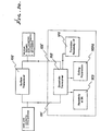
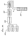
- a block diagram of the invention is shown in Fig. 1 a .
- a downhole transceiver 100 transmits at 101 either drilling parameters or the results of formation evaluation measurements to a transceiver 102 at the surface, or receives signals from a surface transmitter for power management or other control requirements.
- the same instrumentation is used for both downhole telemetry and evaluation of formation resistivity and induced polarization (IP) response.
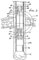
- Fig. 1 b shows the invention in a measurement- while-drilling (MWD) application.
- a bent sub-assembly means 302 in the drillstring provides directional control for the drilling operations.
- Voltage application apparatus is shown in the string and includes battery 24 , insulated wireline 305 , connected at connections 314 and 315 to upper and lower instrument housings 311 and 312 , which house components, such as batteries, sensors and switching apparatus. Voltage or current is applied by electrical contact means 306 and 304 to the drilistring, and then to the formation.
- a borehole drill motor 313 is shown in the string above the drill bit 316 . Upper extent of the string is indicated at 22 , and the borehole appears at 22 a , in formation 22 b .
- a circuitry housing appears at 307 .
- Surface equipment appears at 22 c .
- Figs. 2 a , 2 b and 2 c illustrate three possible configurations of the system used as a means of downhole electric-field telemetry.
- a voltage is impressed across an insulated drill collar 1 , between upper and lower steel drillstring sections 4 and 5 , and drives an electric current through the earth 2 .
- a power source 3 is connected across an upper section 4 of the drilistring, and a lower section 5 of the drillstring, as by wireline components 6 and a signal source (modulator) indicated as a switch 7 , which opens and closes as a function of data to be transmitted, as via a path defined by the drillstring 4 and 5 , and the formation 2 .
- Sections 4 and 5 are typically metallic (steel), and collar 1 is in series with 4 and 5 .
- Signals are detected at the surface of the earth by a receiver 8 , which measures the voltage produced by the downhole transmitter, as between two electrodes associated with 8 at the surface.
- Receiver 8 is in a line 8 a connected between the upper end of the string 4 and 9 a , and a probe 9 into the earth. Note the possible connection 9b to the steel casing in the borehole.
- one electrode comprises an electrical attachment to the drillstring, and the other electrode 9 is connected directly to the earth.
- the insulating section 1 of the drillstring is positioned above the level of a high resistive layer 10 of the formation through which wireline components extend, thus permitting the transmission of downhole information through an insulating geologic formation.
- the drilistring sections 4 b and 5 a consist of steel. Borehole casing is indicated at 4 a .
- FIG. 2 c multiple metallic sections 4 b , 4 c , 5 a , and 5 c of the drilistring are interconnected by insulated sections or collars 1 and 1 a .
- An electrical line 6 interconnects 4 b and 5 a to provide an impedance match and to extend the effective length of the insulating gap.
- Other elements remain as shown in Fig. 2 b .
- Current flow in the formation appears at 400 and 401 .
- An alternate means of telemetry from a downhole location to the surface is implemented by modulating the impedance of the entire assembly as measured from surface connections 9 and 9 a .
- a downhole means for alternately electrically connecting and disconnecting portions of the drillstring is provided by using an appropriately positioned gap or gaps 1 in the drilistring sections electrically connected by insulated wireline components 6 and a switching means 7 .
- the only electrical power required for this means of downhole telemetry is that required for the operation of the electrical switch, thus eliminating the need for downhole power source 3 .
- Fig. 3 shows an electrical circuit equivalent of the drillstring-earth transmission path.
- the Fig. 3 elements are defined as follows:
- voltage difference e 1 --e 2 is maintained by current flow i g across the gap 17 a .
- the voltage across the gap is determined largely by the downhole source voltage at 14 , the internal resistance 15 of the source 14 and wireline 16 , and the resistance 18 of the fluids (mud) in the annulus surrounding the gap sub-assembly.
- the voltage across the gap drives a current i e into the earth 2 .
- This flow of current at the surfaces produces a voltage drop ( V 1 ) across the resistance 21 of the earth at the surface.
- the voltage V 1 is measured by the receiver electronics.
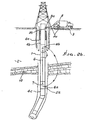
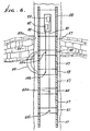
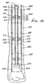
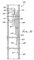
- Fig. 4 Mechanical detail of a two-gap form of the downhole assembly portion of the invention is shown in Fig. 4.
- the bottom hole assembly is either mounted above a downhole motor 34 or one or more drill collars.
- the upper metallic drilistring section 22 is electrically connected to an upper electrical power source, here represented by a battery 24 , as via connection 24 a , housing 23 , and centralizer bowed spring 23 a engaging the string bore.
- Insulated wireline 26 connected to the battery, extends from the lower end of the upper sub-assembly downwardly through one or more insulting drill collars 27 and 29 , and one or more intermediate, conventional, metallic drill collars 28 , to a lower control sub-assembly 31 , and a sensor sub-assembly 33 .
- a drive for the switch 30 in series with line 26 , is shown at 30 a . The drive is modulated by the output of sensor 33 .
- Line 26 electrically connects at 32 to the housing 31 , connected to conductive spring 23 b , which electrically engages the bore of lower drilistring section 22 b .
- the sensor sub-assembly may be located above the motor 34 , as shown, or in an instrumentation mandrel (bit box) directly above the bit. Motor 34 drives (rotates) drill bit 35 .
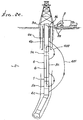
- the invention provides a means for evaluation of resistivity and induced polarization (IP) response at the bit, in the formation surrounding the drilistring or in the formation surrounding a cased borehole.
- IP induced polarization
- a voltage pulse waveform or a set of selected frequencies, is applied across an impedance matched insulated gap or gaps in the drillstring and drill collars configured as shown in Fig. 5.
- the bulk resistivity of the formation surrounding the insulated gap, drill collar or motor, bit-box, and bit can then be determined by well known data reduction methods for geophysical interpretation of formation resistivity and IP response.
- the resistivity at the bit is analytically separated from the bulk resistivity surrounding the bottom hole assembly by noting that, as the bottom hole assembly passes through a formation and the resistivity is measured, changes in the bulk resistivity will be due to resistivity changes at the bit.
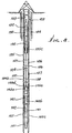
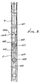
- an upper power and control sub-assembly 36 having one or more current 37 and guard 38 electrodes is mounted on or in and insulated from the drilistring 39 .
- This sub-assembly also carries a power source 40 and control and switching electronics 41 . See also driver 41 a for switch arm 41 .
- An insulated tubular drill collar or gap sub-assembly 42 separates the upper power and control sub-assembly from the motor housing or lower metallic drill collars 43 .
- a resistivity-at-bit lower sub-assembly capable of azimuthal measurements is housed by a tubular mandrel 44 extending downwardly from the motor 43 .
- This mandrel carries an instrumentation package directly above the bit 45 .
- the instrument package comprises a set of one or more guarded or unguarded current electrodes 46 mounted on and insulated from the mandrel or drill collar; and a means 48 a is provided for connecting lower extent of the wireline 48 to the current electrodes 46 individually, or in combination, at each level.
- Each electrode is shown as surrounded by an insulated guard electrode 47 and associated electronics to provide focusing and to reduce return currents along the motor housing or drill collar. Accordingly, electrical field "lines" can be established at different azimuth locations about the string axis.
- Fig. 5 also represents the combined use of MWD (measure while drilling) technique, together with one of multiple electrodes, as referred to, to measure formation properties. Measured voltage or current values are either interpreted as formation resistivity or IP at control sub-assembly for transmission to the surface by the methods described in the previous paragraph, or the values themselves are transmitted to the surface for interpretation. In this case, the results of formation evaluation are equivalent to sensor output.
- Fig. 6 schematically illustrates this configuration.
- Other similar configurations are possible corresponding to the various electrode configurations developed for (surface) resistivity and IP measurements.
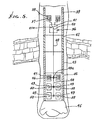
- one or more gap sub-assemblies and wireline system components are used to provide formation resistivity measurements at distances from the borehole previously unobtainable by the prior art.
- a series of insulated, tubular drill collars or gap sub-assemblies 57 , and electrically conducting drill collars or sections of drillstring 58 and 59 are connected in a dipole-dipole configuration, in accordance with known surface geophysics.
- a voltage is applied via source 82 by conductor means 80 and connection means 58a and 58b across conducting sections 58 and 59 , which act as effective current electrodes.
- Electric current 84 is thereby driven from the conducting sections into the formation 85 surrounding the borehole 85 a .
- Receiver means 83 is electrically connected to conducting sections 60 and 61 by conductor means 81 , and connection means 60a and 60b , and the receiver means detects the potential difference between such conducting sections, which act as effective potential electrodes.
- the electrical resistivity of the formation surrounding the borehole can be determined from such receiver measurements and knowledge of the voltage at source 82 .
- the apparatus is configured so as to provide measurement of variable azimuthal resistivity in the formation adjacent to the drillstring.
- a power source at 68 a and suitably driven switching circuits at 67 and 71 drive current along paths 77 into and in the formations, through electrodes 65 and 73 , located around the circumference of upper and lower sub-assemblies 64 and 72 , mounted between upper and lower sections of the drillstring 63 and 63 a , and connected to the power source by an insulated wireline 70.
- An insulated, intermediate section of the string appears at 69 .
- a downhole motor appears above the drill bit 75 at 76 .
- the current flow at electrodes 65 and 73 may be focused by guard electrodes at 74 and 66 .
- Switches 67 and 71 operate to azimuthally distribute the voltage application to upper and lower electrodes at different azimuth locations. Such switches are programmably driven, as at 67 a and 71 a .
- Multiple voltage-sensing electrodes 81 , 82 , 83, and 84 are mounted on the circumference of lower sub-assembly 72 . Potential differences between various voltage sensors are selected by the upper control sub-assembly via wireline connection 70 . In a manner similar to operation of apparatus described and shown in Fig. 5, azimuthal resistivity values adjacent to the borehole are interpreted and transmitted to the surface.
- the string includes metallic drill pipe, with sections 104 extending from the earth surface downwardly in a borehole 120 , to connect at 121 to the upper end of insulative collar 106 .
- Metallic drillstring section 105 is connected at 122 to the lower end of collar 106 , and extends downwardly toward a drill bit not shown.
- the non-conductive portion of collar 106 may consist of very high-strength composite material, such as KEVLAR, or glass fibers in resin.
- String components 121 and 122 are metallic components of collar 106 having pin and box connection to the drill pipe section, and tapered or conical bonded connections to the non-conductive portion of collar 106 at 126 and 127.
- Drilling fluid typically flows downwardly in the string and through bore 128 in 106 ; and flows upwardly about the string to carry borehole cuttings to the surface.
- a battery pack (source of voltage) 130 is typically located in hanging sub-assembly 135 above 106 , one terminal of the source of voltage in electrical connection with centralizer (belly-type) springs 132 located between the battery pack housings 130 and the bore 133 of 104 . An electrical connection is thereby established to the upper string section 104 .
- Hanging sub-assembly 135 supports pack 130 in position, as shown, and may be of any suitable form. Note hang support location 135 c .
- Wireline 138 extends downwardly from the battery pack, through the insulating collar 106 to connect to pulser means 140 a in the lower drilistring section. That pulser means is electrically connected to centralizer (belly-type) springs 141 contacting the bore 142 of lower string section 105 . Accordingly, the drillstring sections 104 and 105 near the collar 106 act as effective upper and lower electrodes, one to pass current into the formation, and the other to receive current flow back from the formation.
- a second battery pack and housing 140 b supplies power to pulser means 140 a and sensor means 140 c .
- the latter means 140 c produces signals which are encoded by pulser means 140 a .
- a hang support at 140 d carries 140 b .
- a modulator means housed in pressure barrel 320 controls flow of electrical current trough wireline 6 to the drillstring 5 by means of an electrical connection from the modulator housing to a pressure barrel 320 , and from that pressure barrel to the drilistring by electrically conductive drilling fluids or centralizer means 322 .
- Signals from the sensor package, housed in pressure barrel 323 are carried by line or cable means 325 to a multiplexer means housed in barrel 320 , and from there to modulator means also housed in barrel 320 .
- Power is supplied from source housed in pressure barrel 324 to the sensors by means 328 , to the multiplexer and to the modulator by means 327 .
- the entire assembly is supported by hanging sub-assembly 135 a carried by the string, and constrained from rotation by means 135 b .
- the transceiver/sensor package is shown in its functional relation to the drillstring in Fig. 10.
- An insulated wireline 6 is connected from one terminal of a source of voltage or current 24 to the conductive string section at the lower end of a resistive section of the drilistring shown schematically at 303 .
- the other terminal of said source is connected to the conductive string section at the upper end of said resistive section.
- a means 309 for modulating or reversing polarity of the source 24 in response to the output of sensors 307 a is provided.
- the multiple sensor outputs 1 through "n" are combined by a multiplexer 307 b before input to the modulator 309 .
- the apparatus may also be configured in a manner such that the wellbore casing enhances the conductive path for transmitted currents to the surface.
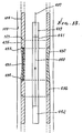
- an insulating section is provided in the wellbore casing, as shown in Fig. 11. Insulating section 350 confines the flow of electrical currents from the section of drilistring 351 above the transmitting gap to the wellbore casing 352 above the insulating section 350 , thereby increasing the current flow 353 between receiver electrodes 9 and 9 a proximate the surface. Note connection of surface line 8 a to the casing at 9 b .
- Non-conducting sub-assemblies may be connected in series, or parallel, or any combination thereof, by use of switching sub-assemblies, as shown in Fig. 12.
- a power source 401 is connected in either positive or negative polarity by switching means 402 to a pair of conductors 403 and 404 insulated from the drillstring and drilling fluids by tubular sheaths 405 and 406 .
- These conductors may be comprised of specially designed insulated wireline components.
- the drillstring is comprised of multiple, non-conducting sub-assemblies 407 and 409 , which are series separated by one or more electrically conducting drillstring components 408 and 410 .
- Connector elements 411 and housing 412 are provided, whereby the conductors are connected to connector elements which connect 413 to electrically conducting drillstring elements 408.
- the non-conducting sub-assemblies are connected in series, parallel or any combination thereof with the power source.
- a modulator 414 is deployed in the bottom hole assembly 415 so as to modulate the flow of electric current in the aforementioned circuit for the purpose of transmission of signals derived from one or more sensors 416 .
- the string includes drill pipe sections, with sections 104 extending from the earth surface in a borehole 120 , to connect at 121 to conductive adapter 435 at the upper end of insulating portion 432 of a non-conductive collar.
- the gap sub-assembly may be provided with a resistive element 431 providing a leakage path for wireline communication with the bottom hole assembly.
- the resistive element 431 is embedded in the insulative material 432 of the gap sub-assembly and electrically connected to upper 435 and lower 436 conductive fittings at 433 and 434 , respectively.
- Communication from the surface to the sensor and modulator electronics is accomplished by a communications path employing wireline means 437 connected through upper battery pack 439 , to insulated wireline 440, to downhole modulator and sensor electronics 442 .
- the insulated wireline components are replaced by a conductor 440 within an insulating tubular sheath 441 , as shown in Fig. 12 .
- Pressure changes or flow of drilling fluid may be encoded for communication from the surface to downhole components of the invention.
- Fig. 14 shows the use of a pressure switch 701 for this purpose. Changes in pressure or flow rate of drilling fluid 702 internal to drillstring 703 is sensed by pressure switch means 701 , which in turn provides input signals to control means 704 .
- Control means 704 is used to control operation of downhole instrumentation, including modulator means 705 , power source 706 , and sensor means 707 .
- changes in the drilling fluid flow rate, controlled from the surface can be used to conserve downhole power consumption by the means of the invention.
- multiple receiver electrodes 501 , 502 , 503 , 504 , and 505 are deployed as shown in Fig. 15. Some of the electrodes may be effected by direct connections 501 a and 505 a , to the active drilistring or casing 501 , or adjacent well casings 505 .
- a switching means 506 and comparator means 507 electrode signals are combined in a manner which provides the best signal reception from a downhole transmitter.
- the switching and comparator means may also be used to provide information on lateral changes in geologic formation, such as the change in resistivity from formation 508 to formation 509 .
- the invention improves methods of downhole target detection, location, and tracking while drilling as by means shown in Fig. 16.
- a time-varying current 521 is injected along the drillstring and into the formation surrounding the drillstring by transmitter means 522 .
- Target casing 523 provides an electrically conductive path in the formation for currents 521 .
- current is concentrated, 524 , on target casing 523 .
- Current flow 524 results in a time varying magnetic field 525 , which is measured by magnetetometer means 526 .
- Time varying magnetic fields 525 measured by means 526 in the bottom hole assembly, bears a known relation to the position of target casing 523 . Such measurements are transmitted to the surface for reception by receiver means 9 and calculation of target position by surface means 528.
- the invention also incorporates several additional improvements over the prior art. These are:
- Fig. 17 is a schematic showing a pipe string 299 having multiple insulated, sub-surface pipe string sections 301-304, across which instrumentation or circuitry 305 and 306 in upper and lower housings 307 and 308 is connected. See connection 309 from circuitry or instrumentation 305 in upper housing 307 to the bore of string section 301; and see connection 311 from circuitry or instrumentation 306 in lower housing 308 to the bore of string section 304. Additional connections are shown at 313, 314 and 315 from circuitry 310 to the string sections 302 to 304. Wirelines are indicated at 320-323.
- Such instrumentation may include batteries, pulse producing means, and circuitry such as amplifiers, and pulse wave shaping equipment, encoding equipment, and frequency and phase shifting means.
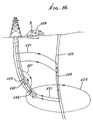
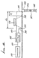
- Fig. 18 shows multiple electrodes, including surface electrodes 330 and 331 spaced at distances d 1 and d 2 from the top of the sub-surface pipe string 333.
- the latter is representative of any of the pipe strings described above and shown in any of Figs. 1-16, containing apparatus as described above and shown in any of Figs. 1-16.
- Such electrodes are typically on or under the ground surface, and adapted to sense changes in electromagnetic fields including electrical fields transmitted in the underground formation and in the pipe string, to the surface, by operation of the down-hole equipment including pulse producing apparatus; and such electrodes and/or the pipe string are also adapted to transmit control signals from the surface to the sub-surface equipment in the pipe string.
- Signal processing means such as a computer, is shown at 340, suitably connected at 341, 342, 343 and 344 with the electrodes and the pipe string, as via amplifier and/or filter equipment 345.
- Upper and lower instrument housings in the pipe string are indicated at 346 and 347.
- a bit box appears at 348.
- the location of a target underground steel casing 349 may be detected, as described above.
- Means 370 may be provided to shift the positions of the electrodes, in relation to the underground formation, to enhance identification of underground formation characteristics.
- the underground instrumentation in the pipe string including pulse producing means is capable of producing short duration pulse wave forms selected to obtain optimum or near optimum transmission of electric field change characteristics in the underground formation.
- Such instrumentation includes means for producing pulse polarity reversal; for producing pulse waveforms of less than 200 ms duration; and for producing such waveforms and characterized by polarity reversal.
- Such waveforms may be of a digital type.
- the pulser means is typically operated at a substantial distance above the drill bit.
- the underground instrumentation may also include a receiver fro receiving signals transmitted downwardly from the surface, for use in controlling equipment such as drilling equipment, or controlling the instrumentation in the upper and lower housings, (switching battery connections, and controlling pulser operation).
- An apparatus for borehole electric-field telemetry that comprises a source of modulated voltage or current, at least one axially non-conductive collar connected between pipe sections in a pipe string, and a system of insulated wireline components providing electrical connections, insulated from drilling fluids, between the ends of the one or more aforementioned insulated collars in the pipe string, to transmit the voltage or current.
Landscapes
- Engineering & Computer Science (AREA)
- Life Sciences & Earth Sciences (AREA)
- Physics & Mathematics (AREA)
- Remote Sensing (AREA)
- Geology (AREA)
- Environmental & Geological Engineering (AREA)
- General Life Sciences & Earth Sciences (AREA)
- Geophysics (AREA)
- Electromagnetism (AREA)
- General Physics & Mathematics (AREA)
- Mining & Mineral Resources (AREA)
- Fluid Mechanics (AREA)
- Geochemistry & Mineralogy (AREA)
- Geophysics And Detection Of Objects (AREA)
- Arrangements For Transmission Of Measured Signals (AREA)
Applications Claiming Priority (2)
| Application Number | Priority Date | Filing Date | Title |
|---|---|---|---|
| US09/265,629 US6396276B1 (en) | 1996-07-31 | 1999-03-09 | Apparatus and method for electric field telemetry employing component upper and lower housings in a well pipestring |
| US265629 | 1999-03-09 |
Publications (2)
| Publication Number | Publication Date |
|---|---|
| EP1035299A2 true EP1035299A2 (de) | 2000-09-13 |
| EP1035299A3 EP1035299A3 (de) | 2005-05-04 |
Family
ID=23011249
Family Applications (1)
| Application Number | Title | Priority Date | Filing Date |
|---|---|---|---|
| EP00104928A Ceased EP1035299A3 (de) | 1999-03-09 | 2000-03-08 | Vorrichtung und Verfahren zur kombinierten Bohrlochsignalübertragung und Bohrlochmessung mit Hilfe eines elektrischen Feldes |
Country Status (4)
| Country | Link |
|---|---|
| US (1) | US6396276B1 (de) |
| EP (1) | EP1035299A3 (de) |
| AU (1) | AU769681B2 (de) |
| CA (1) | CA2300029C (de) |
Cited By (27)
| Publication number | Priority date | Publication date | Assignee | Title |
|---|---|---|---|---|
| RU2190097C2 (ru) * | 2000-12-04 | 2002-09-27 | Общество с ограниченной ответственностью Научно-производственная организация "Новые Технологии Нефтедобычи" | Телеметрическая система для каротажа в процессе бурения |
| RU2193656C1 (ru) * | 2001-05-28 | 2002-11-27 | Закрытое акционерное общество Научно-производственная фирма "Самарские Горизонты" | Забойная телеметрическая система для работы в экранирующих пластах с высокой проводимостью |
| RU2194161C2 (ru) * | 2000-12-01 | 2002-12-10 | Закрытое акционерное общество Научно-производственная фирма "Самарские Горизонты" | Телеметрическая система контроля забойных параметров |
| RU2200835C2 (ru) * | 2001-05-28 | 2003-03-20 | Закрытое акционерное общество Научно-производственная фирма "Самарские Горизонты" | Забойная телеметрическая система |
| RU2211922C1 (ru) * | 2002-04-17 | 2003-09-10 | ООО Научно-исследовательский институт технических систем "Пилот" | Универсальная телеметрическая система для управления бурением скважин |
| RU2218464C2 (ru) * | 2001-10-18 | 2003-12-10 | Закрытое акционерное общество Научно-производственная фирма "Самарские Горизонты" | Аппаратура проверки работоспособности телеметрической системы |
| RU2219336C2 (ru) * | 2001-02-19 | 2003-12-20 | ООО КБ "Тополь" | Телеметрическая система контроля забойных параметров |
| RU2232888C1 (ru) * | 2002-11-18 | 2004-07-20 | Общество с ограниченной ответственностью Научно-производственная организация "Новые Технологии Нефтедобычи" | Забойная телеметрическая система |
| RU2235179C2 (ru) * | 2001-04-12 | 2004-08-27 | Коновалов Сергей Феодосьевич | Способ бурения наклонных и горизонтальных скважин |
| RU2243377C1 (ru) * | 2003-06-19 | 2004-12-27 | Закрытое акционерное общество Научно-производственная фирма "Самарские Горизонты" | Способ и устройство для контроля забойных параметров в экранирующих пластах с высокой проводимостью |
| GB2405422A (en) * | 2003-08-27 | 2005-03-02 | Prec Drilling Tech Serv Group | Electromagnetic borehole telemetry system incorporating a conductive borehole tubular |
| RU2278256C1 (ru) * | 2005-03-09 | 2006-06-20 | ООО НПП "Промгеосервис" | Забойная телеметрическая система с электромагнитным каналом связи |
| RU2282028C2 (ru) * | 2001-03-09 | 2006-08-20 | Шелл Интернэшнл Рисерч Маатсхаппий Б.В. | Каротажная система для использования в буровой скважине |
| RU2289690C2 (ru) * | 2005-02-03 | 2006-12-20 | Сергей Георгиевич Фурсин | Способ контроля забойных параметров скважины |
| WO2007019319A1 (en) * | 2005-08-04 | 2007-02-15 | Schlumberger Canada Limited | Bi-directional drill string telemetry system for measurement and drilling control |
| GB2437144A (en) * | 2005-08-23 | 2007-10-17 | Schlumberger Holdings | Formation telemetry and sensor system |
| WO2007070777A3 (en) * | 2005-12-13 | 2008-07-10 | Halliburton Energy Serv Inc | Multiple frequency based leakage current correction for imaging in oil-based muds |
| US7493962B2 (en) | 2004-12-14 | 2009-02-24 | Schlumberger Technology Corporation | Control line telemetry |
| RU2347902C2 (ru) * | 2007-04-25 | 2009-02-27 | Николай Николаевич Галкин | Забойная телеметрическая система |
| US7579841B2 (en) | 2005-11-04 | 2009-08-25 | Halliburton Energy Services, Inc. | Standoff compensation for imaging in oil-based muds |
| RU2383730C1 (ru) * | 2008-11-05 | 2010-03-10 | Общество с ограниченной ответственностью Научно-производственная фирма "ВНИИГИС - Забойные телеметрические комплексы" (ООО НПФ "ВНИИГИС - ЗТК") | Способ защиты от перенапряжения электронных схем забойной телеметрической системы с беспроводным каналом связи и турбогенератором и устройство для его реализации |
| US7888941B2 (en) | 2005-11-04 | 2011-02-15 | Halliburton Energy Services, Inc. | Permittivity measurements with oil-based mud imaging tool |
| US8183863B2 (en) | 2005-11-10 | 2012-05-22 | Halliburton Energy Services, Inc. | Displaced electrode amplifier |
| US8212568B2 (en) | 2005-11-04 | 2012-07-03 | Halliburton Energy Services, Inc. | Oil based mud imaging tool with common mode voltage compensation |
| US9765615B2 (en) | 2013-08-28 | 2017-09-19 | Evolution Engineering Inc. | Optimizing electromagnetic telemetry transmissions |
| US9863239B2 (en) | 2014-06-19 | 2018-01-09 | Evolution Engineering Inc. | Selecting transmission frequency based on formation properties |
| US9976415B2 (en) | 2015-05-27 | 2018-05-22 | Evolution Engineering Inc. | Electromagnetic telemetry system with compensation for drilling fluid characteristics |
Families Citing this family (38)
| Publication number | Priority date | Publication date | Assignee | Title |
|---|---|---|---|---|
| US6801136B1 (en) * | 1999-10-01 | 2004-10-05 | Gas Research Institute | Method of reducing noise in a borehole electromagnetic telemetry system |
| US7071697B2 (en) * | 2001-01-04 | 2006-07-04 | Schlumberger Technology Corporation | Centralizer including measurement means |
| US7250768B2 (en) * | 2001-04-18 | 2007-07-31 | Baker Hughes Incorporated | Apparatus and method for resistivity measurements during rotational drilling |
| DK1581721T3 (da) * | 2003-01-07 | 2006-10-09 | Gregson William Martin Spring | Kommunikationssystem til anvendelse i et borehul |
| US7066282B2 (en) * | 2003-12-23 | 2006-06-27 | Schlumberger Technology Corporation | Apparatus and methods for measuring formation characteristics in presence of conductive and non-conductive muds |
| US7080699B2 (en) * | 2004-01-29 | 2006-07-25 | Schlumberger Technology Corporation | Wellbore communication system |
| BRPI0613349A2 (pt) * | 2005-06-20 | 2011-01-04 | Halliburton Energy Serv Inc | método de diagrafia de resistividade e aparelho de diagrafia de resistividade |
| US20070017671A1 (en) * | 2005-07-05 | 2007-01-25 | Schlumberger Technology Corporation | Wellbore telemetry system and method |
| US8004421B2 (en) * | 2006-05-10 | 2011-08-23 | Schlumberger Technology Corporation | Wellbore telemetry and noise cancellation systems and method for the same |
| US8629782B2 (en) * | 2006-05-10 | 2014-01-14 | Schlumberger Technology Corporation | System and method for using dual telemetry |
| ATE454532T1 (de) * | 2005-07-29 | 2010-01-15 | Prad Res & Dev Nv | Verfahren und vorrichtung zum senden oder empfangen von information zwischen ein bohrlochmessgerät und der oberfläche |
| US7649474B1 (en) | 2005-11-16 | 2010-01-19 | The Charles Machine Works, Inc. | System for wireless communication along a drill string |
| US8044819B1 (en) * | 2006-10-23 | 2011-10-25 | Scientific Drilling International | Coal boundary detection using an electric-field borehole telemetry apparatus |
| US7782060B2 (en) * | 2006-12-28 | 2010-08-24 | Schlumberger Technology Corporation | Integrated electrode resistivity and EM telemetry tool |
| WO2009080284A2 (en) * | 2007-12-21 | 2009-07-02 | Services Petroliers Schlumberger | Apparatus for receiving and transmitting signals in electromagnetic telemetry system used in a wellbore |
| US8284073B2 (en) * | 2008-04-17 | 2012-10-09 | Schlumberger Technology Corporation | Downlink while pumps are off |
| RU2379504C1 (ru) * | 2008-07-18 | 2010-01-20 | Общество с ограниченной ответственностью "Научно-производственное предприятие "Горизонт" | Устройство передачи информации вдоль ствола скважины |
| CA2744813C (en) * | 2008-12-03 | 2013-06-18 | Halliburton Energy Services, Inc. | Signal propagation across gaps |
| US8113298B2 (en) * | 2008-12-22 | 2012-02-14 | Vector Magnetics Llc | Wireline communication system for deep wells |
| US20100311325A1 (en) * | 2009-06-03 | 2010-12-09 | Marshall Radio Telemetry, Inc. | Systems and methods for through-the-earth communications |
| WO2011022416A1 (en) | 2009-08-17 | 2011-02-24 | Magnum Drilling Services, Inc. | Inclination measurement devices and methods of use |
| US8881414B2 (en) | 2009-08-17 | 2014-11-11 | Magnum Drilling Services, Inc. | Inclination measurement devices and methods of use |
| US8129994B2 (en) * | 2009-10-19 | 2012-03-06 | Smith International Inc | Microresistivity imaging in conductive and nonconductive drilling fluid |
| RU2401944C1 (ru) * | 2009-11-03 | 2010-10-20 | Владимир Алексеевич Королев | Комплексная геофизическая аппаратура на бурильных трубах (варианты) |
| US9158025B2 (en) | 2010-09-16 | 2015-10-13 | Baker Hughes Incorporated | Pad device for resistivity imaging in the wells with oil based drilling fluid |
| US9726008B2 (en) * | 2011-09-26 | 2017-08-08 | Scientific Drilling International, Inc. | Sub-surface formation boundary detection using an electric-field borehole telemetry apparatus |
| WO2014201572A1 (en) | 2013-06-21 | 2014-12-24 | Evolution Engineering Inc. | Methods and apparatus for generating electromagnetic telemetry signals |
| US9920622B2 (en) * | 2013-09-05 | 2018-03-20 | Evolution Engineering Inc. | Transmitting data across electrically insulating gaps in a drill string |
| CA2926612A1 (en) * | 2013-09-30 | 2015-04-02 | Welladv Oil Service Limited | A drilling auxiliary system |
| AU2013408734B2 (en) * | 2013-12-27 | 2017-06-22 | Halliburton Energy Services, Inc. | Drilling collision avoidance apparatus, methods, and systems |
| CA2962194C (en) * | 2014-11-12 | 2019-06-04 | Halliburton Energy Services, Inc. | Well detection using induced magnetic fields |
| WO2016168322A1 (en) | 2015-04-13 | 2016-10-20 | Schlumberger Technology Corporation | Top drive with top entry and line inserted therethrough for data gathering through the drill string |
| US10753198B2 (en) * | 2015-04-13 | 2020-08-25 | Schlumberger Technology Corporation | Downhole instrument for deep formation imaging deployed within a drill string |
| US10900305B2 (en) | 2015-04-13 | 2021-01-26 | Schlumberger Technology Corporation | Instrument line for insertion in a drill string of a drilling system |
| GB2554185B (en) * | 2015-04-23 | 2021-02-24 | Halliburton Energy Services Inc | Magnetic ranging using multiple downhole electrodes |
| AU2015406114A1 (en) * | 2015-08-17 | 2017-12-21 | Halliburton Energy Services, Inc. | Method and article for evaluating mud effect in imaging tool measurement |
| US9803473B2 (en) * | 2015-10-23 | 2017-10-31 | Schlumberger Technology Corporation | Downhole electromagnetic telemetry receiver |
| WO2017083152A1 (en) * | 2015-11-13 | 2017-05-18 | Schlumberger Technology Corporation | Method for placement of surface electrodes for electromagnetic telemetry |
Citations (10)
| Publication number | Priority date | Publication date | Assignee | Title |
|---|---|---|---|---|
| US2389241A (en) | 1944-04-26 | 1945-11-20 | Stanolind Oil & Gas Co | Well logging |
| US3046474A (en) | 1957-07-03 | 1962-07-24 | Arps Corp | Bore-hole logging system and method |
| US4015234A (en) | 1974-04-03 | 1977-03-29 | Erich Krebs | Apparatus for measuring and for wireless transmission of measured values from a bore hole transmitter to a receiver aboveground |
| US4181014A (en) | 1978-05-04 | 1980-01-01 | Scientific Drilling Controls, Inc. | Remote well signalling apparatus and methods |
| US4496174A (en) | 1981-01-30 | 1985-01-29 | Tele-Drill, Inc. | Insulated drill collar gap sub assembly for a toroidal coupled telemetry system |
| US4684946A (en) | 1983-05-06 | 1987-08-04 | Geoservices | Device for transmitting to the surface the signal from a transmitter located at a great depth |
| US4691203A (en) | 1983-07-01 | 1987-09-01 | Rubin Llewellyn A | Downhole telemetry apparatus and method |
| US4980682A (en) | 1989-07-31 | 1990-12-25 | Atlantic Richfield Company | Method of reducing noise in a borehole electromagnetic telemetry system |
| US5130706A (en) | 1991-04-22 | 1992-07-14 | Scientific Drilling International | Direct switching modulation for electromagnetic borehole telemetry |
| US5270703A (en) | 1990-08-31 | 1993-12-14 | Halliburton Company | Bipolar signal amplification or generation |
Family Cites Families (45)
| Publication number | Priority date | Publication date | Assignee | Title |
|---|---|---|---|---|
| US2400170A (en) * | 1942-08-29 | 1946-05-14 | Stanolind Oil & Gas Co | Time cycle telemetering |
| US2924432A (en) | 1956-05-08 | 1960-02-09 | Jan J Arps | Earth borehole logging system |
| US3302457A (en) | 1964-06-02 | 1967-02-07 | Sun Oil Co | Method and apparatus for telemetering in a bore hole by changing drilling mud pressure |
| US3309656A (en) | 1964-06-10 | 1967-03-14 | Mobil Oil Corp | Logging-while-drilling system |
| US3517553A (en) | 1967-12-06 | 1970-06-30 | Tenneco Oil Co | Method and apparatus for measuring and controlling bottomhole differential pressure while drilling |
| FR2109035A5 (de) | 1970-05-11 | 1972-05-26 | Aquitaine Petrole | |
| US3711825A (en) | 1970-07-30 | 1973-01-16 | Schlumberger Technology Corp | Data-signaling apparatus for well drilling tools |
| US3736558A (en) | 1970-07-30 | 1973-05-29 | Schlumberger Technology Corp | Data-signaling apparatus for well drilling tools |
| US3958217A (en) | 1974-05-10 | 1976-05-18 | Teleco Inc. | Pilot operated mud-pulse valve |
| US4078620A (en) | 1975-03-10 | 1978-03-14 | Westlake John H | Method of and apparatus for telemetering information from a point in a well borehole to the earth's surface |
| US4057781A (en) | 1976-03-19 | 1977-11-08 | Scherbatskoy Serge Alexander | Well bore communication method |
| US4072200A (en) | 1976-05-12 | 1978-02-07 | Morris Fred J | Surveying of subterranean magnetic bodies from an adjacent off-vertical borehole |
| US4130169A (en) | 1977-04-22 | 1978-12-19 | Shell Oil Company | Downhole connector for use with drill string telemetering system |
| US4160970A (en) | 1977-11-25 | 1979-07-10 | Sperry Rand Corporation | Electromagnetic wave telemetry system for transmitting downhole parameters to locations thereabove |
| US4351037A (en) | 1977-12-05 | 1982-09-21 | Scherbatskoy Serge Alexander | Systems, apparatus and methods for measuring while drilling |
| US5390153A (en) | 1977-12-05 | 1995-02-14 | Scherbatskoy; Serge A. | Measuring while drilling employing cascaded transmission systems |
| US4262343A (en) | 1979-04-18 | 1981-04-14 | Dresser Industries | Pressure pulse detection apparatus |
| DE3035905C2 (de) | 1980-09-24 | 1982-12-30 | Christensen, Inc., 84115 Salt Lake City, Utah | Vorrichtung zur Fernübertragung von Informationen aus einem Bohrloch zur Erdoberfläche während des Betriebs eines Bohrgeräts |
| US4774694A (en) | 1981-12-15 | 1988-09-27 | Scientific Drilling International | Well information telemetry by variation of mud flow rate |
| US4699352A (en) | 1982-03-08 | 1987-10-13 | Exploration Logging, Inc. | Apparatus for well logging telemetry |
| US4578675A (en) | 1982-09-30 | 1986-03-25 | Macleod Laboratories, Inc. | Apparatus and method for logging wells while drilling |
| US4821035A (en) | 1984-05-01 | 1989-04-11 | Comdisco Resources, Inc. | Method and apparatus using a well casing for transmitting data up a well |
| US4694439A (en) | 1985-07-18 | 1987-09-15 | Scientific Drilling International | Well information telemetry by variation of mud flow rate |
| US4715022A (en) | 1985-08-29 | 1987-12-22 | Scientific Drilling International | Detection means for mud pulse telemetry system |
| FR2600171B1 (fr) | 1986-06-17 | 1990-10-19 | Geoservices | Antenne pour emetteur situe a grande profondeur |
| US4820989A (en) | 1986-11-04 | 1989-04-11 | Paramagnetic Logging, Inc. | Methods and apparatus for measurement of the resistivity of geological formations from within cased boreholes |
| US5081419A (en) | 1990-10-09 | 1992-01-14 | Baker Hughes Incorporated | High sensitivity well logging system having dual transmitter antennas and intermediate series resonant |
| US5061849A (en) | 1988-04-01 | 1991-10-29 | Baker Hughes Incorporated | Externally mounted radioactivity detector for MWD employing radial inline scintillator and photomultiplier tube |
| US5230387A (en) | 1988-10-28 | 1993-07-27 | Magrange, Inc. | Downhole combination tool |
| JP2709135B2 (ja) | 1989-04-11 | 1998-02-04 | 浜松ホトニクス株式会社 | 光信号検出装置 |
| FR2646508B1 (fr) | 1989-04-26 | 1994-04-29 | Geoservices | Procede et appareil pour prelever en continu des echantillons gazeux contenus dans un liquide egalement charge de solides notamment dans une boue de forage petrolier |
| GB2235296B (en) | 1989-08-10 | 1994-11-30 | Exploration Logging Inc | Well logging system arranged for stable,high-sensitivity reception of propagating electromagnetic waves |
| US5189415A (en) | 1990-11-09 | 1993-02-23 | Japan National Oil Corporation | Receiving apparatus |
| US5138313A (en) | 1990-11-15 | 1992-08-11 | Halliburton Company | Electrically insulative gap sub assembly for tubular goods |
| US5155916A (en) | 1991-03-21 | 1992-10-20 | Scientific Drilling International | Error reduction in compensation of drill string interference for magnetic survey tools |
| FR2681461B1 (fr) | 1991-09-12 | 1993-11-19 | Geoservices | Procede et agencement pour la transmission d'informations, de parametres et de donnees a un organe electro-magnetique de reception ou de commande associe a une canalisation souterraine de grande longueur. |
| US5235285A (en) | 1991-10-31 | 1993-08-10 | Schlumberger Technology Corporation | Well logging apparatus having toroidal induction antenna for measuring, while drilling, resistivity of earth formations |
| NO306522B1 (no) | 1992-01-21 | 1999-11-15 | Anadrill Int Sa | Fremgangsmaate for akustisk overföring av maalesignaler ved maaling under boring |
| FR2697119B1 (fr) | 1992-10-16 | 1995-01-20 | Schlumberger Services Petrol | Dispositif émetteur à double raccord isolant, destiné à l'emploi dans un forage. |
| US5321893A (en) | 1993-02-26 | 1994-06-21 | Scientific Drilling International | Calibration correction method for magnetic survey tools |
| US5366018A (en) | 1993-08-16 | 1994-11-22 | Scientific Drilling International | Miniature rope socket assembly for combined mechanical and electrical connection in a borehole wireline |
| US5467083A (en) | 1993-08-26 | 1995-11-14 | Electric Power Research Institute | Wireless downhole electromagnetic data transmission system and method |
| US5512889A (en) | 1994-05-24 | 1996-04-30 | Atlantic Richfield Company | Downhole instruments for well operations |
| US5563512A (en) | 1994-06-14 | 1996-10-08 | Halliburton Company | Well logging apparatus having a removable sleeve for sealing and protecting multiple antenna arrays |
| US5883516A (en) * | 1996-07-31 | 1999-03-16 | Scientific Drilling International | Apparatus and method for electric field telemetry employing component upper and lower housings in a well pipestring |
-
1999
- 1999-03-09 US US09/265,629 patent/US6396276B1/en not_active Expired - Lifetime
-
2000
- 2000-03-06 CA CA002300029A patent/CA2300029C/en not_active Expired - Fee Related
- 2000-03-08 EP EP00104928A patent/EP1035299A3/de not_active Ceased
- 2000-03-09 AU AU20768/00A patent/AU769681B2/en not_active Ceased
Patent Citations (10)
| Publication number | Priority date | Publication date | Assignee | Title |
|---|---|---|---|---|
| US2389241A (en) | 1944-04-26 | 1945-11-20 | Stanolind Oil & Gas Co | Well logging |
| US3046474A (en) | 1957-07-03 | 1962-07-24 | Arps Corp | Bore-hole logging system and method |
| US4015234A (en) | 1974-04-03 | 1977-03-29 | Erich Krebs | Apparatus for measuring and for wireless transmission of measured values from a bore hole transmitter to a receiver aboveground |
| US4181014A (en) | 1978-05-04 | 1980-01-01 | Scientific Drilling Controls, Inc. | Remote well signalling apparatus and methods |
| US4496174A (en) | 1981-01-30 | 1985-01-29 | Tele-Drill, Inc. | Insulated drill collar gap sub assembly for a toroidal coupled telemetry system |
| US4684946A (en) | 1983-05-06 | 1987-08-04 | Geoservices | Device for transmitting to the surface the signal from a transmitter located at a great depth |
| US4691203A (en) | 1983-07-01 | 1987-09-01 | Rubin Llewellyn A | Downhole telemetry apparatus and method |
| US4980682A (en) | 1989-07-31 | 1990-12-25 | Atlantic Richfield Company | Method of reducing noise in a borehole electromagnetic telemetry system |
| US5270703A (en) | 1990-08-31 | 1993-12-14 | Halliburton Company | Bipolar signal amplification or generation |
| US5130706A (en) | 1991-04-22 | 1992-07-14 | Scientific Drilling International | Direct switching modulation for electromagnetic borehole telemetry |
Cited By (37)
| Publication number | Priority date | Publication date | Assignee | Title |
|---|---|---|---|---|
| RU2194161C2 (ru) * | 2000-12-01 | 2002-12-10 | Закрытое акционерное общество Научно-производственная фирма "Самарские Горизонты" | Телеметрическая система контроля забойных параметров |
| RU2190097C2 (ru) * | 2000-12-04 | 2002-09-27 | Общество с ограниченной ответственностью Научно-производственная организация "Новые Технологии Нефтедобычи" | Телеметрическая система для каротажа в процессе бурения |
| RU2219336C2 (ru) * | 2001-02-19 | 2003-12-20 | ООО КБ "Тополь" | Телеметрическая система контроля забойных параметров |
| RU2282028C2 (ru) * | 2001-03-09 | 2006-08-20 | Шелл Интернэшнл Рисерч Маатсхаппий Б.В. | Каротажная система для использования в буровой скважине |
| RU2235179C2 (ru) * | 2001-04-12 | 2004-08-27 | Коновалов Сергей Феодосьевич | Способ бурения наклонных и горизонтальных скважин |
| RU2193656C1 (ru) * | 2001-05-28 | 2002-11-27 | Закрытое акционерное общество Научно-производственная фирма "Самарские Горизонты" | Забойная телеметрическая система для работы в экранирующих пластах с высокой проводимостью |
| RU2200835C2 (ru) * | 2001-05-28 | 2003-03-20 | Закрытое акционерное общество Научно-производственная фирма "Самарские Горизонты" | Забойная телеметрическая система |
| RU2218464C2 (ru) * | 2001-10-18 | 2003-12-10 | Закрытое акционерное общество Научно-производственная фирма "Самарские Горизонты" | Аппаратура проверки работоспособности телеметрической системы |
| RU2211922C1 (ru) * | 2002-04-17 | 2003-09-10 | ООО Научно-исследовательский институт технических систем "Пилот" | Универсальная телеметрическая система для управления бурением скважин |
| RU2232888C1 (ru) * | 2002-11-18 | 2004-07-20 | Общество с ограниченной ответственностью Научно-производственная организация "Новые Технологии Нефтедобычи" | Забойная телеметрическая система |
| RU2243377C1 (ru) * | 2003-06-19 | 2004-12-27 | Закрытое акционерное общество Научно-производственная фирма "Самарские Горизонты" | Способ и устройство для контроля забойных параметров в экранирующих пластах с высокой проводимостью |
| GB2405422A (en) * | 2003-08-27 | 2005-03-02 | Prec Drilling Tech Serv Group | Electromagnetic borehole telemetry system incorporating a conductive borehole tubular |
| GB2421753A (en) * | 2003-08-27 | 2006-07-05 | Prec Energy Services Ltd | Electromagnetic borehole telemetry system |
| GB2421753B (en) * | 2003-08-27 | 2006-10-18 | Prec Energy Services Ltd | Electromagnetic borehole telemetry system incorporating a conductive borehole tubular |
| US7126492B2 (en) | 2003-08-27 | 2006-10-24 | Weatherford Canada Partnership | Electromagnetic borehole telemetry system incorporating a conductive borehole tubular |
| US7145473B2 (en) | 2003-08-27 | 2006-12-05 | Precision Drilling Technology Services Group Inc. | Electromagnetic borehole telemetry system incorporating a conductive borehole tubular |
| GB2405422B (en) * | 2003-08-27 | 2007-08-08 | Prec Drilling Tech Serv Group | Electromagnetic borehole telemetry system incorporating a conductive borehole tubular |
| US7493962B2 (en) | 2004-12-14 | 2009-02-24 | Schlumberger Technology Corporation | Control line telemetry |
| RU2289690C2 (ru) * | 2005-02-03 | 2006-12-20 | Сергей Георгиевич Фурсин | Способ контроля забойных параметров скважины |
| RU2278256C1 (ru) * | 2005-03-09 | 2006-06-20 | ООО НПП "Промгеосервис" | Забойная телеметрическая система с электромагнитным каналом связи |
| WO2007019319A1 (en) * | 2005-08-04 | 2007-02-15 | Schlumberger Canada Limited | Bi-directional drill string telemetry system for measurement and drilling control |
| GB2437144B (en) * | 2005-08-23 | 2008-07-23 | Schlumberger Holdings | Formation evaluation system and method |
| GB2437144A (en) * | 2005-08-23 | 2007-10-17 | Schlumberger Holdings | Formation telemetry and sensor system |
| US7495446B2 (en) | 2005-08-23 | 2009-02-24 | Schlumberger Technology Corporation | Formation evaluation system and method |
| US7579841B2 (en) | 2005-11-04 | 2009-08-25 | Halliburton Energy Services, Inc. | Standoff compensation for imaging in oil-based muds |
| US8212568B2 (en) | 2005-11-04 | 2012-07-03 | Halliburton Energy Services, Inc. | Oil based mud imaging tool with common mode voltage compensation |
| US7888941B2 (en) | 2005-11-04 | 2011-02-15 | Halliburton Energy Services, Inc. | Permittivity measurements with oil-based mud imaging tool |
| US8183863B2 (en) | 2005-11-10 | 2012-05-22 | Halliburton Energy Services, Inc. | Displaced electrode amplifier |
| WO2007070777A3 (en) * | 2005-12-13 | 2008-07-10 | Halliburton Energy Serv Inc | Multiple frequency based leakage current correction for imaging in oil-based muds |
| US8030937B2 (en) | 2005-12-13 | 2011-10-04 | Halliburton Energy Services, Inc. | Multiple frequency based leakage correction for imaging in oil based muds |
| RU2347902C2 (ru) * | 2007-04-25 | 2009-02-27 | Николай Николаевич Галкин | Забойная телеметрическая система |
| RU2383730C1 (ru) * | 2008-11-05 | 2010-03-10 | Общество с ограниченной ответственностью Научно-производственная фирма "ВНИИГИС - Забойные телеметрические комплексы" (ООО НПФ "ВНИИГИС - ЗТК") | Способ защиты от перенапряжения электронных схем забойной телеметрической системы с беспроводным каналом связи и турбогенератором и устройство для его реализации |
| US9765615B2 (en) | 2013-08-28 | 2017-09-19 | Evolution Engineering Inc. | Optimizing electromagnetic telemetry transmissions |
| US9988897B2 (en) | 2013-08-28 | 2018-06-05 | Evolution Engineering Inc. | Optimizing electromagnetic telemetry transmissions |
| US10233747B2 (en) | 2013-08-28 | 2019-03-19 | Evolution Engineering Inc. | Optimizing electromagnetic telemetry transmissions |
| US9863239B2 (en) | 2014-06-19 | 2018-01-09 | Evolution Engineering Inc. | Selecting transmission frequency based on formation properties |
| US9976415B2 (en) | 2015-05-27 | 2018-05-22 | Evolution Engineering Inc. | Electromagnetic telemetry system with compensation for drilling fluid characteristics |
Also Published As
| Publication number | Publication date |
|---|---|
| CA2300029A1 (en) | 2000-09-09 |
| AU769681B2 (en) | 2004-01-29 |
| EP1035299A3 (de) | 2005-05-04 |
| US6396276B1 (en) | 2002-05-28 |
| CA2300029C (en) | 2005-11-01 |
| AU2076800A (en) | 2000-09-14 |
Similar Documents
| Publication | Publication Date | Title |
|---|---|---|
| US6396276B1 (en) | Apparatus and method for electric field telemetry employing component upper and lower housings in a well pipestring | |
| US5883516A (en) | Apparatus and method for electric field telemetry employing component upper and lower housings in a well pipestring | |
| US6188223B1 (en) | Electric field borehole telemetry | |
| US7126492B2 (en) | Electromagnetic borehole telemetry system incorporating a conductive borehole tubular | |
| AU2018206790B2 (en) | Transmitting data across electrically insulating gaps in a drill string | |
| CA2959346C (en) | Electromagnetic telemetry for measurement and logging while drilling and magnetic ranging between wellbores | |
| US6188222B1 (en) | Method and apparatus for measuring resistivity of an earth formation | |
| US10830036B2 (en) | Well monitoring using casing centralizers | |
| CN103835705A (zh) | 井下测量信息传输系统 | |
| US10227868B2 (en) | Electromagnetic telemetry using capacitive surface electrodes | |
| CN202954809U (zh) | 井下测量信息传输系统 | |
| US20250369350A1 (en) | Method and Apparatus For Deep Electromagnetic Communication |
Legal Events
| Date | Code | Title | Description |
|---|---|---|---|
| PUAI | Public reference made under article 153(3) epc to a published international application that has entered the european phase |
Free format text: ORIGINAL CODE: 0009012 |
|
| AK | Designated contracting states |
Kind code of ref document: A2 Designated state(s): AT BE CH CY DE DK ES FI FR GB GR IE IT LI LU MC NL PT SE |
|
| AX | Request for extension of the european patent |
Free format text: AL;LT;LV;MK;RO;SI |
|
| PUAL | Search report despatched |
Free format text: ORIGINAL CODE: 0009013 |
|
| AK | Designated contracting states |
Kind code of ref document: A3 Designated state(s): AT BE CH CY DE DK ES FI FR GB GR IE IT LI LU MC NL PT SE |
|
| AX | Request for extension of the european patent |
Extension state: AL LT LV MK RO SI |
|
| 17P | Request for examination filed |
Effective date: 20050919 |
|
| AKX | Designation fees paid |
Designated state(s): AT BE CH CY DE DK ES FI FR GB GR IE IT LI LU MC NL PT SE |
|
| STAA | Information on the status of an ep patent application or granted ep patent |
Free format text: STATUS: THE APPLICATION HAS BEEN REFUSED |
|
| 18R | Application refused |
Effective date: 20080626 |