EP1035367A1 - Dispositif de forage pour un robinet de branchement - Google Patents
Dispositif de forage pour un robinet de branchement Download PDFInfo
- Publication number
- EP1035367A1 EP1035367A1 EP00104674A EP00104674A EP1035367A1 EP 1035367 A1 EP1035367 A1 EP 1035367A1 EP 00104674 A EP00104674 A EP 00104674A EP 00104674 A EP00104674 A EP 00104674A EP 1035367 A1 EP1035367 A1 EP 1035367A1
- Authority
- EP
- European Patent Office
- Prior art keywords
- valve
- tool
- spindle
- valve body
- shaft
- Prior art date
- Legal status (The legal status is an assumption and is not a legal conclusion. Google has not performed a legal analysis and makes no representation as to the accuracy of the status listed.)
- Granted
Links
- 238000010079 rubber tapping Methods 0.000 claims abstract description 22
- 230000002093 peripheral effect Effects 0.000 claims 1
- 239000002245 particle Substances 0.000 description 2
- 238000007789 sealing Methods 0.000 description 2
- 238000006073 displacement reaction Methods 0.000 description 1
- 238000010438 heat treatment Methods 0.000 description 1
Images




Classifications
-
- F—MECHANICAL ENGINEERING; LIGHTING; HEATING; WEAPONS; BLASTING
- F16—ENGINEERING ELEMENTS AND UNITS; GENERAL MEASURES FOR PRODUCING AND MAINTAINING EFFECTIVE FUNCTIONING OF MACHINES OR INSTALLATIONS; THERMAL INSULATION IN GENERAL
- F16L—PIPES; JOINTS OR FITTINGS FOR PIPES; SUPPORTS FOR PIPES, CABLES OR PROTECTIVE TUBING; MEANS FOR THERMAL INSULATION IN GENERAL
- F16L41/00—Branching pipes; Joining pipes to walls
- F16L41/04—Tapping pipe walls, i.e. making connections through the walls of pipes while they are carrying fluids; Fittings therefor
- F16L41/06—Tapping pipe walls, i.e. making connections through the walls of pipes while they are carrying fluids; Fittings therefor making use of attaching means embracing the pipe
-
- F—MECHANICAL ENGINEERING; LIGHTING; HEATING; WEAPONS; BLASTING
- F16—ENGINEERING ELEMENTS AND UNITS; GENERAL MEASURES FOR PRODUCING AND MAINTAINING EFFECTIVE FUNCTIONING OF MACHINES OR INSTALLATIONS; THERMAL INSULATION IN GENERAL
- F16L—PIPES; JOINTS OR FITTINGS FOR PIPES; SUPPORTS FOR PIPES, CABLES OR PROTECTIVE TUBING; MEANS FOR THERMAL INSULATION IN GENERAL
- F16L41/00—Branching pipes; Joining pipes to walls
- F16L41/08—Joining pipes to walls or pipes, the joined pipe axis being perpendicular to the plane of a wall or to the axis of another pipe
- F16L41/16—Joining pipes to walls or pipes, the joined pipe axis being perpendicular to the plane of a wall or to the axis of another pipe the branch pipe comprising fluid cut-off means
Definitions
- the invention relates to a valve tapping fitting with a housing, a saddle that can be attached to a pipe, one Branch connector and a valve upper part that can be screwed into the housing, in which a valve body and cutting tool for cutting the pipeline can be moved linearly via a spindle are arranged.
- Such a valve tapping fitting is for example from DE 44 08 817 known. It serves to branch off pipelines to create, for example, to establish a house connection.
- Saddle heating wires integrated by applying a voltage can be heated so far that the saddle with the pipeline is welded and thereby a tight connection between the Tapping valve and the pipeline can be produced
- the tapping tool is on one Bolted on the valve body.
- the valve body is running in an internal thread provided in the housing. He will turn offset, the valve body lowers along with it screwed tool rotating in the direction of the pipeline and drill them with the tool. Will the valve body Turned further, it descends to that in the lower part of the housing provided valve seat and seals the tapping point.
- a disadvantage of this configuration is that the seal of the Valve body is rotatably placed on the valve seat and thus subject to wear, which will destroy the seal can result.
- the thread connection directly exposed to the medium between valve body and housing, when the valve is opened so that medium or entrained Suspended particles dirt particles get into the threads can cause threaded connection failure or tightness when shutting off or opening the valve.
- WO 97/23747 discloses a valve tapping fitting in which the The valve body and the attached tool can only be lowered linearly are so that the valve can execute without a rotary movement comes to the system on the valve seat.
- Disadvantage of this Training is that the tool is the "tapping point" on the pipeline punched out so that burrs and coarse shavings can arise that remain in the pipeline and are washed away there, and / or narrow the "tapping diameter".
- Tapping valve can be improved.
- a generic valve tapping fitting is used to solve the problem characterized in that the valve body and the tool are rotatably arranged relative to each other, but the spindle non-rotatably axially slidably connected to the tool and the valve body is provided with a thread for receiving the spindle, so that when the spindle rotates the tool is a combined rotary and translational and the valve body a pure performs translatory movement.
- This configuration makes the pipeline more desirable advantageously rotated bored while sealing the valve body is only lowered linearly onto its seat, so that it is not subject to wear. Moreover the threaded connection lies within the valve body, so that they are not exposed to any inflowing medium when the valve is opened is what increases lifespan and long is easy Operability guaranteed.
- the valve body is preferably hollow and accommodates inside a shaft of the tool coaxially. The components can then be inserted into each other and easily assembled.
- the valve body is with a non-rotatable in the valve upper part Arranged shaft provided, which is preferably a polygonal Has circumferential contour.
- the upper part of the housing has inside a corresponding polygonal training.
- the non-rotatable connection can also be a tongue and groove connection or the like.
- the shank of the tool is preferably hollow, and has at least one guide lug inside, which in a corresponding one in the axial direction of the spindle engages provided groove.
- the shaft with two guide lugs is particularly preferred and the spindle with two grooves each arranged diametrically.
- the sealing of the valve body against the shaft of the tool is preferably carried out via an O-ring.
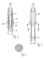
- the valve tapping valve with the pipeline 1 connected.
- the thread 3 Screwed in housing 6.
- the upper valve part 8 can be screwed in.
- the seal between the valve upper part 8 and the housing 6 is carried out via the O-ring 7.
- a spindle 9 is rotatably mounted into a thread 20 provided in the stem 19 of the valve body 10 can be screwed in.
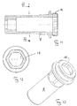
- the stem 19 of the valve body 10 has an outer polygonal Shape as shown in Figure 15. Inside the upper valve part 8 is a corresponding polygonal profile 18 is provided. Via this polygonal profile 18, the valve body 10 is non-rotatable connected to the valve upper part 8.
- the valve body 10 is drilled hollow.
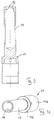
- the tool 11 is with a shaft 17 which is opposite the tool body 11a is narrower.
- the tool 11 is provided with the shaft 17 inserted coaxially into the valve body 10 and stored inside.
- the valve body 10 is opposite Sealed shaft 17 of the tool 11.
- the spindle 9 has 2 diametrical on its outside Grooves 15, which run in the axial direction and the thread Interrupt 9a of spindle 9.
- the grooves 15 are designed that they cooperate with the guide lugs 16 of the tool 11 can.
Landscapes
- Engineering & Computer Science (AREA)
- General Engineering & Computer Science (AREA)
- Mechanical Engineering (AREA)
- Lift Valve (AREA)
- Branch Pipes, Bends, And The Like (AREA)
- Permanent Field Magnets Of Synchronous Machinery (AREA)
- Forging (AREA)
- Details Of Valves (AREA)
Applications Claiming Priority (2)
| Application Number | Priority Date | Filing Date | Title |
|---|---|---|---|
| DE19910998 | 1999-03-12 | ||
| DE19910998A DE19910998C2 (de) | 1999-03-12 | 1999-03-12 | Ventil-Anbohrarmatur |
Publications (2)
| Publication Number | Publication Date |
|---|---|
| EP1035367A1 true EP1035367A1 (fr) | 2000-09-13 |
| EP1035367B1 EP1035367B1 (fr) | 2001-12-12 |
Family
ID=7900697
Family Applications (1)
| Application Number | Title | Priority Date | Filing Date |
|---|---|---|---|
| EP00104674A Expired - Lifetime EP1035367B1 (fr) | 1999-03-12 | 2000-03-03 | Dispositif de forage pour un robinet de branchement |
Country Status (3)
| Country | Link |
|---|---|
| EP (1) | EP1035367B1 (fr) |
| AT (1) | ATE210793T1 (fr) |
| DE (2) | DE19910998C2 (fr) |
Families Citing this family (5)
| Publication number | Priority date | Publication date | Assignee | Title |
|---|---|---|---|---|
| DE10208376C1 (de) * | 2002-02-27 | 2003-09-25 | Ewe Wilhelm Gmbh & Co Kg | Ventil-Anbohrarmatur |
| DE10302917B3 (de) * | 2003-01-24 | 2004-07-15 | Friatec Ag | Ventil-Anbohrarmatur |
| DE10320997B4 (de) * | 2003-05-09 | 2009-10-15 | Wilhelm Ewe Gmbh & Co Kg | Ventil-Anbohrarmatur |
| DE202004014886U1 (de) * | 2004-09-23 | 2006-02-02 | Viega Gmbh & Co. Kg | Hilfsventil für eine Anbohrarmatur |
| DE102005011725B4 (de) * | 2005-03-11 | 2009-08-27 | Wilhelm Ewe Gmbh & Co Kg | Ventil-Anbohrarmatur |
Citations (2)
| Publication number | Priority date | Publication date | Assignee | Title |
|---|---|---|---|---|
| DE3744693A1 (de) * | 1987-02-12 | 1988-12-15 | Puspas Armaturen Gmbh | Ventilanbohrschelle |
| WO1997023747A1 (fr) * | 1995-12-22 | 1997-07-03 | Georg Fischer Rohrleitungssysteme Ag | Robinet auto-perceur a soupape |
Family Cites Families (1)
| Publication number | Priority date | Publication date | Assignee | Title |
|---|---|---|---|---|
| DE4408817C1 (de) * | 1994-03-16 | 1995-06-22 | Ewe Wilhelm Gmbh & Co Kg | Ventil-Anbohrarmatur mit integrierter Betriebsabsperrung |
-
1999
- 1999-03-12 DE DE19910998A patent/DE19910998C2/de not_active Expired - Fee Related
-
2000
- 2000-03-03 EP EP00104674A patent/EP1035367B1/fr not_active Expired - Lifetime
- 2000-03-03 AT AT00104674T patent/ATE210793T1/de not_active IP Right Cessation
- 2000-03-03 DE DE50000052T patent/DE50000052D1/de not_active Expired - Lifetime
Patent Citations (2)
| Publication number | Priority date | Publication date | Assignee | Title |
|---|---|---|---|---|
| DE3744693A1 (de) * | 1987-02-12 | 1988-12-15 | Puspas Armaturen Gmbh | Ventilanbohrschelle |
| WO1997023747A1 (fr) * | 1995-12-22 | 1997-07-03 | Georg Fischer Rohrleitungssysteme Ag | Robinet auto-perceur a soupape |
Also Published As
| Publication number | Publication date |
|---|---|
| DE19910998C2 (de) | 2001-11-15 |
| DE50000052D1 (de) | 2002-01-24 |
| ATE210793T1 (de) | 2001-12-15 |
| DE19910998A1 (de) | 2000-09-21 |
| EP1035367B1 (fr) | 2001-12-12 |
Similar Documents
| Publication | Publication Date | Title |
|---|---|---|
| DE4217982C2 (de) | Ventil-Anbohrarmatur | |
| WO2004071244A3 (fr) | Systeme d'entrainement lineaire electromoteur | |
| DE8318405U1 (de) | Fernsteuerbare drosseleinrichtung | |
| DE3830395C1 (en) | Boring fitting | |
| DE2709466A1 (de) | Ventilanbohrschelle | |
| EP1035367B1 (fr) | Dispositif de forage pour un robinet de branchement | |
| DE2944520A1 (de) | Ventiloberteil | |
| EP0811799B1 (fr) | Appareil de perçage avec vanne pour tuyaux de distribution à fluide sous pression en matière plastique | |
| DE4239573C2 (de) | Anbohrarmatur für unter Mediumdruck stehende Rohrleitungen | |
| DE19510169A1 (de) | Futter mit Kupplung | |
| DE4134046A1 (de) | Absperrarmatur | |
| DE10320997B4 (de) | Ventil-Anbohrarmatur | |
| DE10210844B4 (de) | Ventil-Anbohrarmatur | |
| DE10302917B3 (de) | Ventil-Anbohrarmatur | |
| EP0585600A1 (fr) | Tête de broche pour revolver | |
| DE29924062U1 (de) | Ventil-Anbohrarmatur | |
| DE3107648C1 (de) | Ventilanborarmatur | |
| DE102005011725B4 (de) | Ventil-Anbohrarmatur | |
| DE19801851A1 (de) | Anbohrarmatur für untere Mediendruck stehende Kunststoffrohre | |
| DE8524528U1 (de) | Ventiloberteil für Sanitärarmaturen | |
| EP3591271A1 (fr) | Partie supérieure de soupape | |
| DE3928843C2 (fr) | ||
| DE102014224088A1 (de) | Anbohrarmatur | |
| DE29709441U1 (de) | Drehbare Verbindung für Sanitärarmaturen | |
| DE29822813U1 (de) | Ventiloberteil für Armaturen |
Legal Events
| Date | Code | Title | Description |
|---|---|---|---|
| PUAI | Public reference made under article 153(3) epc to a published international application that has entered the european phase |
Free format text: ORIGINAL CODE: 0009012 |
|
| 17P | Request for examination filed |
Effective date: 20000712 |
|
| AK | Designated contracting states |
Kind code of ref document: A1 Designated state(s): AT CH DE LI |
|
| AX | Request for extension of the european patent |
Free format text: AL;LT;LV;MK;RO;SI |
|
| AKX | Designation fees paid |
Free format text: AT CH DE LI |
|
| GRAG | Despatch of communication of intention to grant |
Free format text: ORIGINAL CODE: EPIDOS AGRA |
|
| 17Q | First examination report despatched |
Effective date: 20010619 |
|
| GRAG | Despatch of communication of intention to grant |
Free format text: ORIGINAL CODE: EPIDOS AGRA |
|
| GRAH | Despatch of communication of intention to grant a patent |
Free format text: ORIGINAL CODE: EPIDOS IGRA |
|
| GRAH | Despatch of communication of intention to grant a patent |
Free format text: ORIGINAL CODE: EPIDOS IGRA |
|
| GRAA | (expected) grant |
Free format text: ORIGINAL CODE: 0009210 |
|
| AK | Designated contracting states |
Kind code of ref document: B1 Designated state(s): AT CH DE LI |
|
| REF | Corresponds to: |
Ref document number: 210793 Country of ref document: AT Date of ref document: 20011215 Kind code of ref document: T |
|
| REG | Reference to a national code |
Ref country code: CH Ref legal event code: NV Representative=s name: BRAUN & PARTNER PATENT-, MARKEN-, RECHTSANWAELTE Ref country code: CH Ref legal event code: EP |
|
| REF | Corresponds to: |
Ref document number: 50000052 Country of ref document: DE Date of ref document: 20020124 |
|
| PLBE | No opposition filed within time limit |
Free format text: ORIGINAL CODE: 0009261 |
|
| STAA | Information on the status of an ep patent application or granted ep patent |
Free format text: STATUS: NO OPPOSITION FILED WITHIN TIME LIMIT |
|
| 26N | No opposition filed | ||
| PGFP | Annual fee paid to national office [announced via postgrant information from national office to epo] |
Ref country code: CH Payment date: 20080320 Year of fee payment: 9 |
|
| PGFP | Annual fee paid to national office [announced via postgrant information from national office to epo] |
Ref country code: AT Payment date: 20080319 Year of fee payment: 9 |
|
| PG25 | Lapsed in a contracting state [announced via postgrant information from national office to epo] |
Ref country code: AT Free format text: LAPSE BECAUSE OF NON-PAYMENT OF DUE FEES Effective date: 20090303 |
|
| REG | Reference to a national code |
Ref country code: CH Ref legal event code: PL |
|
| PG25 | Lapsed in a contracting state [announced via postgrant information from national office to epo] |
Ref country code: CH Free format text: LAPSE BECAUSE OF NON-PAYMENT OF DUE FEES Effective date: 20090331 Ref country code: LI Free format text: LAPSE BECAUSE OF NON-PAYMENT OF DUE FEES Effective date: 20090331 |
|
| REG | Reference to a national code |
Ref country code: DE Ref legal event code: R082 Ref document number: 50000052 Country of ref document: DE Representative=s name: GRAMM, LINS & PARTNER PATENT- UND RECHTSANWAEL, DE |
|
| PGFP | Annual fee paid to national office [announced via postgrant information from national office to epo] |
Ref country code: DE Payment date: 20190327 Year of fee payment: 20 |
|
| REG | Reference to a national code |
Ref country code: DE Ref legal event code: R071 Ref document number: 50000052 Country of ref document: DE |