EP1035402A2 - Einrichtung und Verfahren zum künstlichen Auslösen von Lawinen - Google Patents
Einrichtung und Verfahren zum künstlichen Auslösen von Lawinen Download PDFInfo
- Publication number
- EP1035402A2 EP1035402A2 EP00103199A EP00103199A EP1035402A2 EP 1035402 A2 EP1035402 A2 EP 1035402A2 EP 00103199 A EP00103199 A EP 00103199A EP 00103199 A EP00103199 A EP 00103199A EP 1035402 A2 EP1035402 A2 EP 1035402A2
- Authority
- EP
- European Patent Office
- Prior art keywords
- previous
- explosive
- detonator
- container
- explosive charge
- Prior art date
- Legal status (The legal status is an assumption and is not a legal conclusion. Google has not performed a legal analysis and makes no representation as to the accuracy of the status listed.)
- Granted
Links
- 238000000034 method Methods 0.000 title claims description 21
- 239000002360 explosive Substances 0.000 claims abstract description 85
- 230000006353 environmental stress Effects 0.000 claims abstract description 5
- 238000004880 explosion Methods 0.000 claims description 16
- 239000011521 glass Substances 0.000 claims description 12
- 238000005422 blasting Methods 0.000 claims description 8
- 230000009471 action Effects 0.000 claims description 6
- 239000000463 material Substances 0.000 claims description 6
- 230000035939 shock Effects 0.000 claims description 6
- 230000003213 activating effect Effects 0.000 claims description 5
- 238000002485 combustion reaction Methods 0.000 claims description 5
- 230000004927 fusion Effects 0.000 claims description 5
- 239000002184 metal Substances 0.000 claims description 5
- 238000005096 rolling process Methods 0.000 claims description 5
- 229910000831 Steel Inorganic materials 0.000 claims description 4
- 230000000694 effects Effects 0.000 claims description 4
- 239000011122 softwood Substances 0.000 claims description 4
- 239000010959 steel Substances 0.000 claims description 4
- 229920001084 poly(chloroprene) Polymers 0.000 claims description 3
- 238000011084 recovery Methods 0.000 claims description 3
- 239000007799 cork Substances 0.000 claims description 2
- 230000035882 stress Effects 0.000 description 5
- 241001125879 Gobio Species 0.000 description 3
- SNIOPGDIGTZGOP-UHFFFAOYSA-N Nitroglycerin Chemical compound [O-][N+](=O)OCC(O[N+]([O-])=O)CO[N+]([O-])=O SNIOPGDIGTZGOP-UHFFFAOYSA-N 0.000 description 2
- 230000007613 environmental effect Effects 0.000 description 2
- 239000007789 gas Substances 0.000 description 2
- 229960003711 glyceryl trinitrate Drugs 0.000 description 2
- 230000007246 mechanism Effects 0.000 description 2
- 230000037452 priming Effects 0.000 description 2
- SPSSULHKWOKEEL-UHFFFAOYSA-N 2,4,6-trinitrotoluene Chemical compound CC1=C([N+]([O-])=O)C=C([N+]([O-])=O)C=C1[N+]([O-])=O SPSSULHKWOKEEL-UHFFFAOYSA-N 0.000 description 1
- 208000019695 Migraine disease Diseases 0.000 description 1
- 206010047700 Vomiting Diseases 0.000 description 1
- 239000000853 adhesive Substances 0.000 description 1
- 230000001070 adhesive effect Effects 0.000 description 1
- 230000015572 biosynthetic process Effects 0.000 description 1
- 238000004891 communication Methods 0.000 description 1
- 230000008878 coupling Effects 0.000 description 1
- 238000010168 coupling process Methods 0.000 description 1
- 238000005859 coupling reaction Methods 0.000 description 1
- 229920001971 elastomer Polymers 0.000 description 1
- 230000005674 electromagnetic induction Effects 0.000 description 1
- 238000003912 environmental pollution Methods 0.000 description 1
- 238000000605 extraction Methods 0.000 description 1
- 239000012634 fragment Substances 0.000 description 1
- 230000006698 induction Effects 0.000 description 1
- 238000003780 insertion Methods 0.000 description 1
- 230000037431 insertion Effects 0.000 description 1
- 238000009434 installation Methods 0.000 description 1
- 230000007257 malfunction Effects 0.000 description 1
- 238000004519 manufacturing process Methods 0.000 description 1
- 238000002156 mixing Methods 0.000 description 1
- 238000012986 modification Methods 0.000 description 1
- 230000004048 modification Effects 0.000 description 1
- 239000000126 substance Substances 0.000 description 1
- 239000000015 trinitrotoluene Substances 0.000 description 1
- 238000011179 visual inspection Methods 0.000 description 1
- 230000008673 vomiting Effects 0.000 description 1
- 238000005303 weighing Methods 0.000 description 1
- 239000002023 wood Substances 0.000 description 1
Images




Classifications
-
- F—MECHANICAL ENGINEERING; LIGHTING; HEATING; WEAPONS; BLASTING
- F42—AMMUNITION; BLASTING
- F42D—BLASTING
- F42D1/00—Blasting methods or apparatus, e.g. loading or tamping
- F42D1/04—Arrangements for ignition
-
- F—MECHANICAL ENGINEERING; LIGHTING; HEATING; WEAPONS; BLASTING
- F42—AMMUNITION; BLASTING
- F42B—EXPLOSIVE CHARGES, e.g. FOR BLASTING, FIREWORKS, AMMUNITION
- F42B3/00—Blasting cartridges, i.e. case and explosive
-
- F—MECHANICAL ENGINEERING; LIGHTING; HEATING; WEAPONS; BLASTING
- F42—AMMUNITION; BLASTING
- F42B—EXPLOSIVE CHARGES, e.g. FOR BLASTING, FIREWORKS, AMMUNITION
- F42B39/00—Packaging or storage of ammunition or explosive charges; Safety features thereof; Cartridge belts or bags
- F42B39/30—Containers for detonators or fuzes
-
- F—MECHANICAL ENGINEERING; LIGHTING; HEATING; WEAPONS; BLASTING
- F42—AMMUNITION; BLASTING
- F42D—BLASTING
- F42D3/00—Particular applications of blasting techniques
Definitions
- the present invention relates to a device and a method for artificially causing an avalanche.
- Avalanches are generally originated by large amounts of snow that usually settles in the valleys below the mountain crest-line, where slopes are more marked and that, due to thermal variations or other stress, suddenly break off and fall downstream at increasing speed.
- Snow masses which can potentially cause avalanches, for reasons depending on the meteorological situations of the environment, can be essentially made up of masses of powdery snow possibly covered with a superficial icy layer originated by low temperatures.
- the explosive charges used are made up of nitro-glycerine explosives, primed with a traditional method with detonator and fuse, placed on the surface of the snow mass by one or two operators who, after having reached the site for laying the charge on foot or by helicopter, and having lighted the fuses, remain on site, in most cases insecurely sheltered from the explosion, until the avalanche thus caused completes its course.
- Said method presents several disadvantages among which the fact that the nitro-glycerine explosives used are especially shock-sensitive, above all at low temperatures; additionally, when handled, they cause illness such as strong migraines and vomiting.
- the operators are compelled to stay in the proximity of the charge explosion area; thus, they can be involved in the explosion or in the caused avalanche itself.
- Another method for artificially causing an avalanche consists in using an explosive charge with an electronic timer, which can be launched from a helicopter thanks to a small parachute with which it is provided.
- the weight of the explosive mass of said device has a fixed value, and the explosive with which it is made, must be made up by the operator, right before use, by mixing two special substances, and inserting afterwards said explosive into a special container.
- the explosive charge in question is provided with a single detonator and thus, in case of malfunction of the same, there are no other possibilities of making it blast at the desired moment.
- Another system consists in using an apparatus transported by helicopter, adapted to launch explosive charges on the snow.
- This apparatus is extremely expensive, very bulky and unsafe.
- gas-exp fixed systems, called “gas-exp”, which are capable of causing avalanches as a consequence of the explosion of a particular gas.
- the object of the present invention is that of solving the above-mentioned disadvantages of the prior art.
- an important purpose of the present invention is that of devising a device and a method for artificially causing an avalanche, which could be extremely safe in that they are not subject to environmental stresses and are provided with an actuation system having two different safeties, an ignition-based one and a mechanical one, operating in cascade.
- Another purpose of the present invention is that of manufacturing a device and a method for artificially causing an avalanche, using a type of explosive especially insensitive to any type of stress and which, in addition, should be provided with a double system for priming the explosive charge instead of a single one so as to guarantee a complete operation safety.
- a further purpose of the present invention is that of providing for a device and a method for artificially causing an avalanche, which allow the recovery of the explosive charge, in the very remote case of explosion failure, in total safety conditions since the charge is not capable of accidentally blasting because of external pressures such as, for example, extraneous currents or shocks.
- Another purpose of the present invention is that of providing for a device and a method for artificially causing an avalanche, which would be extremely easy to use and have great flexibility of use since the explosive mass can be of different weight according to the situation.
- a further purpose of the present invention is that of providing for a device and a method for artificially causing an avalanche, which allow to transporting the explosive charge by helicopter and releasing it in extremely fast and safe way, allowing to placing the explosive charge in the selected point, thus optimising the effects of the explosion and preventing the explosive charge from moving from where it has been placed, even in case of very leaning slopes and icy snow.
- Another purpose of the present invention is that of providing for a device and a method for artificially causing an avalanche, which is completely safe and prevents possible undesired explosions also in the remote case of accidental shocks or falls from the helicopter used to transport the explosive charge.
- a further purpose of the present invention is that of providing for a device and a method for artificially causing an avalanche, to be used in a range of temperatures comprised between -40 and +70 °C, having an extremely simple structure together with a valid functionality and having a reasonable price, so as to be widely used at low prices.
- a device for artificially causing an avalanche comprising an explosive mass and a system for activating the same, characterised in that said actuation system comprises an actuator provided with first safety means insensitive to all types of electric currents, and to environmental stresses, and at least second safety means that can be actuated by said first safety means only when said device is placed on the fixed mass of snow.
- Object of the present invention patent is also a method for artificially causing an avalanche, characterised in that it consists in determining the point for laying down an explosive charge made up of an explosive mass and in a system for activating the same; of arming said actuation system by inserting at least one detonator into at least one special seat; of bringing an explosive charge into a non-alignment position - in contrast to the action of a mechanical timer - with respect to said detonator; of holding said explosive charge into said position by means of a locking member; of associating said actuation system to said explosive mass; of igniting at least one fuse having a fixed combustion time and connected to said detonator; of arranging said explosive charge in said fixed point; and of removing said locking member so that said explosive charge aligns, after a fixed time, with at least said detonator and with said explosive mass.
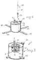
- the device for artificially causing an avalanche according to the invention referred to as a whole with the reference numeral 1
- the actuation system 3 comprises an actuator 4, provided with first safety means 5, insensitive to all types of electric current, and to environmental stresses, and at least second safety means 6, which can be actuated by the first safety means only when the device is arranged in the selected point of the mantle of snow so as to cause an avalanche in optimum conditions.
- Actuator 4 is provided with a hollow body having a cylindrical shape 7, suitably made of a biodegradable material, which can be closed on the upper side with an upper plate 8 and on the lower side with a lower plate 9 through a "bayonet" joint 19.
- the body 7 of the actuator is made of an extremely stiff and resistant material having a coefficient of thermal expansion which is practically equal to zero, and the ignition temperature is equal to about 430 °C.
- Body 7 does not shrink at low temperatures, and thus it allows adjusting the operation of the mobile mechanisms with minimal dimensional tolerance.
- the low ignition temperature causes an immediate combustion of the material on the explosion, and the formation of micro-fragments originated by the collapse of the structure, thus preventing environmental pollution.
- the operation of the first safety means 5 is ignition-based, free from any type of stress, including those due to electric currents.
- the first safety means 5 is defined by an igniter, and in particular by two frictioned igniters 9 that are connected to at least one fuse, and in particular, to two respective fuses 10, connected in turn to at least one detonator, and more precisely, to two detonators 11.
- each of the two portions of safety fuse 10 has a length of 100 centimetres and a combustion rate equal to 0.4 centimetres/second.
- Respective end portions of fuses 10 are connected to the frictioned igniters 9 inserted into respective holes 12 located on the upper plate 8.
- fuses 10 After exiting the body 7 of the actuator, fuses 10 are externally wound around it, and are housed at their opposed ends into horizontal cylindrical seats 13, where they are fixedly held inside the same seats as detonators 11.
- detonators 11 are provided in pairs to guarantee an ignition safety in at least one of them, and seats 13 are in reciprocal communication with one another so as to allow the blasting of both detonators also in the case one of them is not actuated by the relating fuse 10.
- the second safety means comprises a throttle element 15 having an elongated shape, which is provided with at least one explosive charge, or "booster”, referred to with 16, in one end portion.
- the lower plate 9 On its face, the lower plate 9 is provided with an aperture 20, which is occluded by the throttle element 15.
- the throttle element 15 is mobile from a first position wherein the explosive charge 16 is not aligned with the two detonators 11, and at least a second position wherein the explosive charge 16 is aligned with detonators 11.
- the throttle element is mobile from the second position to the first position and vice versa in contrast to and for the action of a mechanical timer 21.
- Timer 21 is provided with a quadrangular shaft 22 which engages in the relating seat 23 of the throttle element 15, which can rotate around pivot 24 located on the lower plate 9.
- the throttle element is held into the first position of non-alignment of the explosive charge 16 with detonators 11 thanks to the engagement of a split pin 25, which passes through hole 26 of the upper plate 8 and of the housing seat 27 of timer 21 to engage with a hole 28 located on the throttle element.
- timer 21 aligns the throttle element and thus, the explosive charge 16 with detonators 11, and consequently, with the explosive mass inserted by fusion into a cylindrical container 31 inside which, into seat 32, actuator 4 is housed.
- the explosive mass 30, which can be made up of trinitrotoluene or tritolite, is actuated by detonators 11 through the explosive charge 16 present on the throttle element 15 when the latter is in the second alignment position, through aperture 20, also with the explosive mass 30.
- the device also comprises some means to release container 31 from a helicopter, as a whole referred to with numeral 40, see figures 4 and 5, in the selected point of the mantle of snow, and adapted to cause the avalanche.
- release means 40 is adapted - as it will be better detailed hereafter - to actuate the mechanical timer 21, thus bringing the throttle element 15 into an armament position.
- the release means 40 comprises a "throwaway" cable 41, also made with a biodegradable material, and wound around a special roller arranged on the helicopter, which is provided at one end with the split pin or gudgeon 25 adapted to lock the throttle element 15 into the second position of non-alignment with detonators 11 and with the explosive mass 30.
- the cable is provided with a slot 42 adapted to engage with a hook 43 hinged on the edge of container 31 and mobile in contrast to and for the action of a pre-calibrated spring 44.
- slot 42 disengages from hook 43, which returns to its initial position thanks to spring 44.
- the device comprises anti-rolling means for the container; in particular, two bars 45 that are inserted into respective through holes 46 present on the same so as to create a hindrance to the rolling of container 31 along the mass of snow.
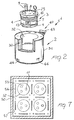
- detonators 11 are advantageously contained into safety containment means of the same that is provided with a container 50 capable of preventing in the case of undesired explosion of detonators 11 consequences outside the container.
- container 50 is adapted to cause the dissipation of the energy freed by the explosion of the detonators through the deformation of the structures wherein detonators 11 are inserted.
- the detonators are arranged in groups of three inserted in a glass of soft steel 52 in which lead 53 has been introduced by fusion.
- glasses 52 are arranged into special pits 54 obtained in a soft-wood parallelepiped 55.
- the outer surfaces of the container are internally covered with a neoprene layer 57 for the purpose of protecting it from vibrations.
- a wooden cover 58 is provided in the upper side; in its lower side, said cover is provided with lowered areas 59 in correspondence with the upper side of glasses 52.
- the cover is externally coated with neoprene.
- the entire container is inserted into a primary container, not shown, made up of steel sheets welded to one another, and also provided with a cover that is fixed to the body thereof through suitable means.
- the method for artificially causing an avalanche consists in the following operating sequence.
- the throttle element Before embarking the container of the explosive mass and of the actuation system of the same on a helicopter, the throttle element is made rotate from the second position to the first position, non-aligned with respect to the seats of detonators 11.
- the operation of the mechanical timer is tested to check whether it is adapted to bring the explosive charge, located inside the throttle element, into an alignment position with respect to said seats.
- the explosive charge 16 is manually brought back, through aperture 20, in a non-aligned position, and is held in said position through the insertion of split pin 25 inside hole 28 thereof.
- bars 45 are inserted into the through holes 46 of the container; the actuation system is removed from the relating container; two detonators are taken from the armoured container 50, and are inserted into the respective seats 13, which are then occluded with plugs 14.
- the actuation system is inserted into container 31 through, for example, a bayonet joint 60 located on the lower plate 9.
- the explosive charge is ready to be released and, should the detonators explode, though it is an extremely remote event, the explosive mass would not explode since the explosive charge 16, or "booster", is not aligned with the detonators and with the explosive mass.
- Slot 42 is applied onto hook 43, and the end of cable 41 is fastened through a simple knot, to split pin 25.
- the explosive charge is freed from the hook as soon as it touches the snow; then, a traction is effected on the cable so as to extract the split pin from its seat, thus leaving the throttle element freely rotate so as to align the explosive charge, or "booster", with the detonators; the cable is cut onboard of the helicopter, and it is released.
- the explosive charge will be in the second position of alignment with the detonators by virtue of the rotation operated by the mechanical timer.
- the detonators After about 4 minutes and 10 seconds from the ignition of the fuses, the detonators will explode, thus causing the cascaded blasting of the explosive charge, or "booster", and of the underlying explosive mass.
- the invention achieves the proposed purposes, obtaining several important advantages.
- a device and a method for artificially causing an avalanche have been invented which carry out the priming steps in a totally mechanical-igniferous way, so as to prevent the explosive charge from running the risk of untimely explosions caused by all types of extraneous currents that can generate in high-mountain environments and in a helicopter.
- the laying method through the use of a (throwaway) cable and of a release hook at the end of the traction allows positioning the explosive charge exactly in the point selected, thus optimising the effect of the explosion.
- the explosive charge is available with different weights of the explosive mass.
- actuator 4 is provided with an additional safety made up of a split pin 80 adapted to hold the throttle element 15 into position, locked into the first position.
- container 31 can be provided with horizontal ribs 81 for the purpose of having a greater surface resistance and for holding the explosive it contains, inserted by fusion, with greater efficacy.
- a metal mass 83 weighing about 1 kg, is provided at the end of cable 41, and a half ring 84 is provided in the lower side of said metal mass.
- the cable Spaced from the metal mass, the cable is also provided with three safety hooks 85, the first two of which are connected to igniters 9 so as to actuate them when the explosive charge is laid on the snow through cable 41, instead of activating it onboard of the helicopter.
- the third hook is connected to split pin 80, which is disconnected from its seat during the cable recovery and the actuation of the igniters.
- Container 50 can also be manufactured so as to be provided, in place of the steel glasses 52, with a wooden parallelepiped 86, wherein the detonators are housed, immersed into a honeycomb structure 91, as shown in figure 11.
- a parallelepiped 86 made of soft wood (fir), horizontally divided into two parts 89 and 90.
- the above-mentioned extractable structure is removed, and in the opening thus obtained, the rheophores of the electrical detonators are arranged.
- the box is laterally provided with two handles 95 and two coupling systems for fastening it to the loading platform of the helicopter.
- the capability of the container of absorbing and dissipating the energy freed from the detonator blasting is due both to its strong outer structure, and to the particular "honeycomb" configuration of its inner structure.
- detonators with particular reference to electrical detonators it houses, cannot be in any way subject to stresses due to electric, induction, contact or electrostatic currents.
- the materials, shapes and dimensions used can be of any type according to the needs.
Landscapes
- Engineering & Computer Science (AREA)
- General Engineering & Computer Science (AREA)
- Devices Affording Protection Of Roads Or Walls For Sound Insulation (AREA)
- Prostheses (AREA)
- Transition And Organic Metals Composition Catalysts For Addition Polymerization (AREA)
- Orthopedics, Nursing, And Contraception (AREA)
- Current-Collector Devices For Electrically Propelled Vehicles (AREA)
- Air Bags (AREA)
- Surgical Instruments (AREA)
- Buildings Adapted To Withstand Abnormal External Influences (AREA)
- Input Circuits Of Receivers And Coupling Of Receivers And Audio Equipment (AREA)
- Photoreceptors In Electrophotography (AREA)
Applications Claiming Priority (2)
| Application Number | Priority Date | Filing Date | Title |
|---|---|---|---|
| IT1999MI000493A IT1311085B1 (it) | 1999-03-11 | 1999-03-11 | Dispositivo e procedimento per provocare artificialmente una valanga |
| ITMI990493 | 1999-03-11 |
Publications (3)
| Publication Number | Publication Date |
|---|---|
| EP1035402A2 true EP1035402A2 (de) | 2000-09-13 |
| EP1035402A3 EP1035402A3 (de) | 2001-02-28 |
| EP1035402B1 EP1035402B1 (de) | 2004-10-20 |
Family
ID=11382236
Family Applications (1)
| Application Number | Title | Priority Date | Filing Date |
|---|---|---|---|
| EP00103199A Expired - Lifetime EP1035402B1 (de) | 1999-03-11 | 2000-02-17 | Einrichtung zum küntlichen Auslösen von Lawinen |
Country Status (5)
| Country | Link |
|---|---|
| EP (1) | EP1035402B1 (de) |
| AT (1) | ATE280384T1 (de) |
| DE (1) | DE60014993T2 (de) |
| ES (1) | ES2231059T3 (de) |
| IT (1) | IT1311085B1 (de) |
Cited By (2)
| Publication number | Priority date | Publication date | Assignee | Title |
|---|---|---|---|---|
| WO2007096524A1 (fr) * | 2006-02-24 | 2007-08-30 | Technologie Alpine De Securite - Tas | Dispositif de declenchement d’avalanche |
| CN118640745A (zh) * | 2024-08-16 | 2024-09-13 | 华侨大学 | 一种便于输送的气胀弱爆致裂器 |
Families Citing this family (1)
| Publication number | Priority date | Publication date | Assignee | Title |
|---|---|---|---|---|
| DE102009037705B4 (de) | 2009-08-18 | 2014-03-27 | Geräte- und Vorrichtungsbau Spitzner OHG | Verfahren und Vorrichtung zum Auslösen von Lawinenabgängen |
Family Cites Families (9)
| Publication number | Priority date | Publication date | Assignee | Title |
|---|---|---|---|---|
| WO1980001511A1 (en) * | 1979-01-19 | 1980-07-24 | P Schroecksnadel | Process and device of controlled triggering of avalanches |
| FR2535045A1 (fr) * | 1982-10-26 | 1984-04-27 | Commissariat Energie Atomique | Projectile declencheur d'avalanches |
| GB2185093B (en) * | 1983-12-22 | 1988-09-14 | Mp Compact Energy Ltd | Demolition device and method of preparing same |
| IL81199A0 (en) * | 1987-01-08 | 1987-09-16 | Israel State | Modular demolition charge unit |
| CH675023A5 (de) * | 1988-01-12 | 1990-08-15 | Zermatt Air Ag | |
| DE9016841U1 (de) * | 1990-12-13 | 1992-04-16 | Gebrüder Junghans GmbH, 7230 Schramberg | Kampfmittelräumeinrichtung |
| DE4302252C1 (en) * | 1992-02-24 | 1993-09-09 | Franz 82467 Garmisch-Partenkirchen De Wendl | System for artificially triggering snow avalanches from helicopter - involves lowering explosive means from helicopter by special electrical cable with load reception housing, distance holder and detonator. |
| EP0690285A1 (de) * | 1994-06-29 | 1996-01-03 | Air Zermatt | Verfahren und Vorrichtung zum Auslösen von Lawinen mittels Explosivladungen |
| DE59609540D1 (de) * | 1996-03-26 | 2002-09-12 | Innova Patent Gmbh Wolfurt | Einrichtung zum Auslösen einer Lawine od. dgl. |
-
1999
- 1999-03-11 IT IT1999MI000493A patent/IT1311085B1/it active
-
2000
- 2000-02-17 AT AT00103199T patent/ATE280384T1/de active
- 2000-02-17 EP EP00103199A patent/EP1035402B1/de not_active Expired - Lifetime
- 2000-02-17 DE DE60014993T patent/DE60014993T2/de not_active Expired - Lifetime
- 2000-02-17 ES ES00103199T patent/ES2231059T3/es not_active Expired - Lifetime
Non-Patent Citations (1)
| Title |
|---|
| None |
Cited By (4)
| Publication number | Priority date | Publication date | Assignee | Title |
|---|---|---|---|---|
| WO2007096524A1 (fr) * | 2006-02-24 | 2007-08-30 | Technologie Alpine De Securite - Tas | Dispositif de declenchement d’avalanche |
| FR2897931A1 (fr) * | 2006-02-24 | 2007-08-31 | Technologie Alpine De Securite | Dispositif de declenchement d'avalanche |
| US8342096B2 (en) | 2006-02-24 | 2013-01-01 | Technologie Alpine De Securite-Tas | Avalanche triggering system |
| CN118640745A (zh) * | 2024-08-16 | 2024-09-13 | 华侨大学 | 一种便于输送的气胀弱爆致裂器 |
Also Published As
| Publication number | Publication date |
|---|---|
| DE60014993D1 (de) | 2004-11-25 |
| ATE280384T1 (de) | 2004-11-15 |
| EP1035402A3 (de) | 2001-02-28 |
| DE60014993T2 (de) | 2006-02-09 |
| EP1035402B1 (de) | 2004-10-20 |
| ITMI990493A1 (it) | 2000-09-11 |
| ES2231059T3 (es) | 2005-05-16 |
| IT1311085B1 (it) | 2002-02-28 |
Similar Documents
| Publication | Publication Date | Title |
|---|---|---|
| US11840339B2 (en) | Method, device, and system for avalanche control | |
| EP1035402A2 (de) | Einrichtung und Verfahren zum künstlichen Auslösen von Lawinen | |
| US3736877A (en) | Ignition system for a parachute flare | |
| US8904939B2 (en) | Avalanche-inducing device | |
| US20050257673A1 (en) | Reusable bomb diffuser | |
| EP0448898A1 (de) | Vorrichtung zum Abschiessen einer Rakete wobei der Geschossbehälter das Abschussrohr bildet | |
| CA1222657A (en) | Multiple charge munition, e.g. a combinated anti-tank and anti-personnel mine for broadcast scattering | |
| CA1222656A (en) | Scatterable anti-tank mine with automatic positioning | |
| EP1228341A2 (de) | Sprengpatrone und die verwendung dieser sprengpatrone | |
| ROGGERO | DEPARTMENT OF THE AIR FORCE | |
| KR102087592B1 (ko) | 양손 사용이 가능한 수류탄의 안전 장전 구조체 및 이를 구비한 수류탄 | |
| TR2022013131U5 (tr) | Her Tür Yüzeye Tutunabilen El Bombası Çözüm | |
| Naus et al. | Ballistics Tests of Fibrous Concrete Dome and Plate Specimens | |
| CHIZALLET | BY LUNCOUPLING BETWEEN MUNITIONS | |
| Gould | The Storage of Bombs in All-Up Condition | |
| Abromeit | United States Military Artillery for Avalanche Control Program: A Brief History in Time | |
| PQC | MINE GUIDE | |
| Chizallet | Reduction of Hazard Zones by Uncoupling Between Munitions | |
| CA1169296A (en) | Mine, especially for tank-combating | |
| HJ3PECSB et al. | LAND MINES | |
| US3382801A (en) | Shielded explosive cutting device | |
| US4429635A (en) | Mine, especially antitank mine | |
| David et al. | Quantity Distances for Ammunition in ISO Containers | |
| TR2021021946A2 (tr) | İnsansız hava araçları için el bombası pim çekme, bırakma ve patlatma geciktirme mekanizması. | |
| Rae | Picatinny Arsenal |
Legal Events
| Date | Code | Title | Description |
|---|---|---|---|
| PUAI | Public reference made under article 153(3) epc to a published international application that has entered the european phase |
Free format text: ORIGINAL CODE: 0009012 |
|
| AK | Designated contracting states |
Kind code of ref document: A2 Designated state(s): AT BE CH CY DE DK ES FI FR GB GR IE IT LI LU MC NL PT SE |
|
| AX | Request for extension of the european patent |
Free format text: AL;LT;LV;MK;RO;SI |
|
| RIC1 | Information provided on ipc code assigned before grant |
Free format text: 7F 42D 3/00 A, 7F 42B 3/00 B, 7F 42D 1/04 B, 7F 42B 39/30 B |
|
| PUAL | Search report despatched |
Free format text: ORIGINAL CODE: 0009013 |
|
| AK | Designated contracting states |
Kind code of ref document: A3 Designated state(s): AT BE CH CY DE DK ES FI FR GB GR IE IT LI LU MC NL PT SE |
|
| AX | Request for extension of the european patent |
Free format text: AL;LT;LV;MK;RO;SI |
|
| 17P | Request for examination filed |
Effective date: 20010327 |
|
| AKX | Designation fees paid |
Free format text: AT BE CH CY DE DK ES FI FR GB GR IE IT LI LU MC NL PT SE |
|
| 17Q | First examination report despatched |
Effective date: 20020716 |
|
| RIC1 | Information provided on ipc code assigned before grant |
Ipc: 7F 42B 39/30 B Ipc: 7F 42D 1/04 B Ipc: 7F 42D 3/00 A Ipc: 7F 42B 3/00 B |
|
| RTI1 | Title (correction) |
Free format text: DEVICE FOR ARTIFICIALLY CAUSING AN AVALANCHE |
|
| GRAP | Despatch of communication of intention to grant a patent |
Free format text: ORIGINAL CODE: EPIDOSNIGR1 |
|
| GRAS | Grant fee paid |
Free format text: ORIGINAL CODE: EPIDOSNIGR3 |
|
| GRAA | (expected) grant |
Free format text: ORIGINAL CODE: 0009210 |
|
| AK | Designated contracting states |
Kind code of ref document: B1 Designated state(s): AT BE CH CY DE DK ES FI FR GB GR IE IT LI LU MC NL PT SE |
|
| PG25 | Lapsed in a contracting state [announced via postgrant information from national office to epo] |
Ref country code: NL Free format text: LAPSE BECAUSE OF FAILURE TO SUBMIT A TRANSLATION OF THE DESCRIPTION OR TO PAY THE FEE WITHIN THE PRESCRIBED TIME-LIMIT Effective date: 20041020 Ref country code: BE Free format text: LAPSE BECAUSE OF FAILURE TO SUBMIT A TRANSLATION OF THE DESCRIPTION OR TO PAY THE FEE WITHIN THE PRESCRIBED TIME-LIMIT Effective date: 20041020 Ref country code: FI Free format text: LAPSE BECAUSE OF FAILURE TO SUBMIT A TRANSLATION OF THE DESCRIPTION OR TO PAY THE FEE WITHIN THE PRESCRIBED TIME-LIMIT Effective date: 20041020 |
|
| REG | Reference to a national code |
Ref country code: GB Ref legal event code: FG4D |
|
| REG | Reference to a national code |
Ref country code: CH Ref legal event code: EP |
|
| REG | Reference to a national code |
Ref country code: IE Ref legal event code: FG4D |
|
| REF | Corresponds to: |
Ref document number: 60014993 Country of ref document: DE Date of ref document: 20041125 Kind code of ref document: P |
|
| PG25 | Lapsed in a contracting state [announced via postgrant information from national office to epo] |
Ref country code: DK Free format text: LAPSE BECAUSE OF FAILURE TO SUBMIT A TRANSLATION OF THE DESCRIPTION OR TO PAY THE FEE WITHIN THE PRESCRIBED TIME-LIMIT Effective date: 20050120 Ref country code: GR Free format text: LAPSE BECAUSE OF FAILURE TO SUBMIT A TRANSLATION OF THE DESCRIPTION OR TO PAY THE FEE WITHIN THE PRESCRIBED TIME-LIMIT Effective date: 20050120 |
|
| REG | Reference to a national code |
Ref country code: SE Ref legal event code: TRGR Ref country code: CH Ref legal event code: NV Representative=s name: STUDIO RAPISARDI S.A. |
|
| PG25 | Lapsed in a contracting state [announced via postgrant information from national office to epo] |
Ref country code: CY Free format text: LAPSE BECAUSE OF FAILURE TO SUBMIT A TRANSLATION OF THE DESCRIPTION OR TO PAY THE FEE WITHIN THE PRESCRIBED TIME-LIMIT Effective date: 20050217 Ref country code: LU Free format text: LAPSE BECAUSE OF NON-PAYMENT OF DUE FEES Effective date: 20050217 Ref country code: IE Free format text: LAPSE BECAUSE OF NON-PAYMENT OF DUE FEES Effective date: 20050217 Ref country code: GB Free format text: LAPSE BECAUSE OF NON-PAYMENT OF DUE FEES Effective date: 20050217 |
|
| PG25 | Lapsed in a contracting state [announced via postgrant information from national office to epo] |
Ref country code: MC Free format text: LAPSE BECAUSE OF NON-PAYMENT OF DUE FEES Effective date: 20050228 |
|
| NLV1 | Nl: lapsed or annulled due to failure to fulfill the requirements of art. 29p and 29m of the patents act | ||
| REG | Reference to a national code |
Ref country code: ES Ref legal event code: FG2A Ref document number: 2231059 Country of ref document: ES Kind code of ref document: T3 |
|
| PLBE | No opposition filed within time limit |
Free format text: ORIGINAL CODE: 0009261 |
|
| STAA | Information on the status of an ep patent application or granted ep patent |
Free format text: STATUS: NO OPPOSITION FILED WITHIN TIME LIMIT |
|
| GBPC | Gb: european patent ceased through non-payment of renewal fee |
Effective date: 20050217 |
|
| 26N | No opposition filed |
Effective date: 20050721 |
|
| ET | Fr: translation filed | ||
| REG | Reference to a national code |
Ref country code: IE Ref legal event code: MM4A |
|
| PG25 | Lapsed in a contracting state [announced via postgrant information from national office to epo] |
Ref country code: PT Free format text: LAPSE BECAUSE OF NON-PAYMENT OF DUE FEES Effective date: 20050320 |
|
| PGFP | Annual fee paid to national office [announced via postgrant information from national office to epo] |
Ref country code: DE Payment date: 20110226 Year of fee payment: 12 Ref country code: SE Payment date: 20110223 Year of fee payment: 12 Ref country code: CH Payment date: 20110219 Year of fee payment: 12 Ref country code: IT Payment date: 20110225 Year of fee payment: 12 Ref country code: AT Payment date: 20110228 Year of fee payment: 12 Ref country code: FR Payment date: 20110315 Year of fee payment: 12 |
|
| PGFP | Annual fee paid to national office [announced via postgrant information from national office to epo] |
Ref country code: ES Payment date: 20110225 Year of fee payment: 12 |
|
| REG | Reference to a national code |
Ref country code: CH Ref legal event code: PL |
|
| PG25 | Lapsed in a contracting state [announced via postgrant information from national office to epo] |
Ref country code: LI Free format text: LAPSE BECAUSE OF NON-PAYMENT OF DUE FEES Effective date: 20120229 Ref country code: CH Free format text: LAPSE BECAUSE OF NON-PAYMENT OF DUE FEES Effective date: 20120229 Ref country code: SE Free format text: LAPSE BECAUSE OF NON-PAYMENT OF DUE FEES Effective date: 20120218 |
|
| REG | Reference to a national code |
Ref country code: FR Ref legal event code: ST Effective date: 20121031 |
|
| PG25 | Lapsed in a contracting state [announced via postgrant information from national office to epo] |
Ref country code: IT Free format text: LAPSE BECAUSE OF NON-PAYMENT OF DUE FEES Effective date: 20120217 |
|
| REG | Reference to a national code |
Ref country code: AT Ref legal event code: MM01 Ref document number: 280384 Country of ref document: AT Kind code of ref document: T Effective date: 20120217 |
|
| REG | Reference to a national code |
Ref country code: DE Ref legal event code: R119 Ref document number: 60014993 Country of ref document: DE Effective date: 20120901 |
|
| PG25 | Lapsed in a contracting state [announced via postgrant information from national office to epo] |
Ref country code: FR Free format text: LAPSE BECAUSE OF NON-PAYMENT OF DUE FEES Effective date: 20120229 Ref country code: AT Free format text: LAPSE BECAUSE OF NON-PAYMENT OF DUE FEES Effective date: 20120217 |
|
| PG25 | Lapsed in a contracting state [announced via postgrant information from national office to epo] |
Ref country code: DE Free format text: LAPSE BECAUSE OF NON-PAYMENT OF DUE FEES Effective date: 20120901 |
|
| REG | Reference to a national code |
Ref country code: ES Ref legal event code: FD2A Effective date: 20130708 |
|
| PG25 | Lapsed in a contracting state [announced via postgrant information from national office to epo] |
Ref country code: ES Free format text: LAPSE BECAUSE OF NON-PAYMENT OF DUE FEES Effective date: 20120218 |