EP1035413A2 - Vorrichtung zur automatischen Prüfung der Gleichmässigkeit von textilem Prüfgut - Google Patents
Vorrichtung zur automatischen Prüfung der Gleichmässigkeit von textilem Prüfgut Download PDFInfo
- Publication number
- EP1035413A2 EP1035413A2 EP99125089A EP99125089A EP1035413A2 EP 1035413 A2 EP1035413 A2 EP 1035413A2 EP 99125089 A EP99125089 A EP 99125089A EP 99125089 A EP99125089 A EP 99125089A EP 1035413 A2 EP1035413 A2 EP 1035413A2
- Authority
- EP
- European Patent Office
- Prior art keywords
- measuring
- test material
- capacitor
- gap
- measuring gap
- Prior art date
- Legal status (The legal status is an assumption and is not a legal conclusion. Google has not performed a legal analysis and makes no representation as to the accuracy of the status listed.)
- Granted
Links
Images



Classifications
-
- G—PHYSICS
- G01—MEASURING; TESTING
- G01N—INVESTIGATING OR ANALYSING MATERIALS BY DETERMINING THEIR CHEMICAL OR PHYSICAL PROPERTIES
- G01N27/00—Investigating or analysing materials by the use of electric, electrochemical, or magnetic means
- G01N27/02—Investigating or analysing materials by the use of electric, electrochemical, or magnetic means by investigating impedance
- G01N27/22—Investigating or analysing materials by the use of electric, electrochemical, or magnetic means by investigating impedance by investigating capacitance
- G01N27/226—Construction of measuring vessels; Electrodes therefor
-
- G—PHYSICS
- G01—MEASURING; TESTING
- G01N—INVESTIGATING OR ANALYSING MATERIALS BY DETERMINING THEIR CHEMICAL OR PHYSICAL PROPERTIES
- G01N27/00—Investigating or analysing materials by the use of electric, electrochemical, or magnetic means
- G01N27/02—Investigating or analysing materials by the use of electric, electrochemical, or magnetic means by investigating impedance
- G01N27/22—Investigating or analysing materials by the use of electric, electrochemical, or magnetic means by investigating impedance by investigating capacitance
- G01N27/24—Investigating the presence of flaws
-
- G—PHYSICS
- G01—MEASURING; TESTING
- G01N—INVESTIGATING OR ANALYSING MATERIALS BY DETERMINING THEIR CHEMICAL OR PHYSICAL PROPERTIES
- G01N33/00—Investigating or analysing materials by specific methods not covered by groups G01N1/00 - G01N31/00
- G01N33/36—Textiles
- G01N33/365—Filiform textiles, e.g. yarns
Definitions
- the invention relates to a device for automatic testing the uniformity of textile test material, especially yarns, Tapes and rovings according to the preamble of claim 1.
- Such a device is used to describe quality and quality-determining parameters on linear textiles Materials automatically when the measurement data is recorded online determine. Different types of test material can automatically can be measured in succession.
- One for the further processing of linear textiles is an important and quality-determining parameter in spinning mills the non-uniformity of the mass distribution over the length of the test material. It characterizes the deviation of the real mass distribution from a homogeneous theoretical distribution over the length of the test material.
- Known uniformity testers are designed so that the capacitive Measuring head from a fixed number of measuring gaps with different Gap width exists, with each measuring gap for one certain fineness range of the test material is used.
- On such uniformity tester is e.g. from EP-A-0 266 611 known.
- the adjustment of the measurement signal during the run of the test material through the measuring gap with different dielectric constant the fiber structure is characterized by a different electronic amplification of the measurement signal achieved.
- the invention has for its object a uniformity tester to create of the type mentioned, which with regard to the positioning of the test material and in relation to the Measurement accuracy and the reproducibility of the measured values improved is.
- the invention advantageously provides that the for Measurement effective width of the measuring gap at the point of the continuous Test material with the help of a positioning device test material remaining in the measuring gap continuously or in Levels is adjustable.
- Such a measuring head only has a single measuring gap in which test material of different fineness is measured can.
- the positioning device With the help of the positioning device, the relative position of the test material in the measuring head and thus the effective width of the Measuring gap can be set, which in a simple manner Numerous measuring gap widths are available for a measurement.
- the measuring capacitor and the reference capacitor preferably exist forming capacitor electrodes from capacitor plates.
- At least one capacitor electrode one from the mounting plate proceeding obliquely, facing the measuring gap Surface has, making the width of the measuring gap increases with increasing distance from the mounting plate. Due to the surface that runs obliquely to the test material at least one of the capacitor electrodes becomes a relative to the mounting plate divergent measuring gap educated. Depending on the positioning of the test material within the Measuring gap is a different effective measuring gap width by setting the flow position of the test material or the Measuring head position available.
- At least one of the other facing capacitor surfaces a stepped surface has, wherein the steps run parallel to the test material.
- the effective of the test material relative to the measuring head Width of the measuring gap can be set.
- the positioning device the measuring head relative to the test material in Moves towards increasing or decreasing width of the measuring gap.
- test material can be moved by moving guide devices be positioned within the measuring gap.
- the positioning device guide devices with the test material relative to the measuring head in Moves towards increasing or decreasing width of the measuring gap.
- the test material is passed parallel within the measuring gap. and repositioned, creating the effective width of the measurement gap is set.
- the positioning device the guide devices also move laterally, so that the Distance of the test material from the capacitor electrodes of the measuring capacitor can be changed.
- an asymmetrical one Distance from the capacitor electrodes delimiting the measuring gap can be set.
- At least one of the Capacitor electrodes transverse to the direction of the test specimen in Direction of increasing or decreasing width of the measuring gap on the mounting plate be moved in parallel. In this case, too the throughput position of the test material can remain unchanged.
- the drive is in all alternative positioning devices coupled with a displacement measuring device which sends a measuring signal to the Control that transmits the effective measuring gap width in this way can calculate.
- the test material can rest on at least one capacitor electrode.
- the test material is preferably on the inner capacitor plate of the measuring gap, causing a restless run of the Test material is prevented during the measurement.
- a preferred development of the invention provides that the Control the drive for a displacement of the capacitor electrodes and / or the guide device for the test material, until the measuring signal of the measuring capacitor with continuous or a stationary test sample a predetermined measurement signal size reached.
- the measuring gap width be optimized in relation to the test material, whereby the Measurement signal strength improved and measurement inaccuracies reduced and the reproducibility of the measured values is increased.
- the material code number is a derived quantity based on the dielectric constants of the different fiber materials is based.
- the capacitor electrodes can have an insulating coating exhibit.
- the measuring head can be used in parallel for an interim calibration to the measuring gap and orthogonal to the mounting plate so far withdrawn until the test material is outside the measuring gap located.
- the measuring head is placed in the housing of the device withdrawn until the test material is exposed.
- At least one of the capacitor electrodes is interchangeable.
- the middle one Interchangeable capacitor plate Preferably the middle one Interchangeable capacitor plate.
- the mounting plate has, for example, a plug connection device on, which transmit a coding signal to the controller can. This enables the controller to determine the capacitor plate size used detect.
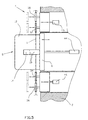
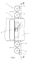
- the test material 1 shows a uniformity tester with a housing 2 and a capacitive measuring head 5 with a measuring capacitor 9 and a reference capacitor 11.
- the test material 1 consists of linear ones textile materials, in particular from yarn, tapes and rovings.
- Such a uniformity tester enables automatic on-line detection of non-uniformity the mass distribution over the length of the test material. This will be different statistical data recorded and calculated.
- a controller 3 coordinates the transport of the test material 1 Carrying out and evaluating the measurement and the settings the measuring head 5 with the aid of positioning devices 44, 46.
- the measuring head 5 has a plurality of capacitor electrodes which are parallel to one another 10, 12, 14 and two outer shielding electrodes 17 on that protrude orthogonally from a mounting plate 6.
- the middle capacitor electrode 12 and the shielding electrodes 17 are grounded, while the capacitor electrodes 10, 14 lie on potential.
- the middle capacitor electrode 12 forms in connection with the one capacitor electrode 14 and the intermediate measuring gap 8 the measuring capacitor 9.
- the same middle capacitor electrode 12 also forms a connection with the capacitor electrode 10 and the intermediate Reference measuring gap 7 the reference capacitor 11. It understands yourself that the measuring capacitor 9 is also used as a reference capacitor and the reference capacitor 11 is also used as a measuring capacitor can be.
- the textile test material 1 is used in a uniformity testing device, as shown in FIG. 1, for example via a disk brake 20 vertically through the measuring gap 8 and below the measuring head 5 above a deflection device 22 between two rollers 24, 26 of a suction device 28 fed so that a continuous measurement on the test material 1 is possible.
- the capacitor electrodes 10, 12, 14 are on the mounting plate 6 mounted on one side, at least the middle Capacitor electrode 12 is interchangeable.
- the exchange the middle capacitor electrode 12 is e.g. over a Connector.
- the connector can be coded so that the controller 3 receives a signal indicating which capacitor electrode 12 is inserted. This allows capacitor electrodes 12 with Measuring columns 8.9 different widths are used to a rough adaptation to very different material densities to reach.
- the entire measuring head is also interchangeable.
- the measuring gap 8 diverges outwards. This is a of the two capacitor electrodes 12, 14, preferably those on Potential capacitor electrode 14, with a plan view 2 obliquely starting from the mounting plate 6 extending side surface 13 facing the measuring gap 8. As a result, the width of the measuring gap 8 increases with increasing Distance from the mounting plate 6 to.
- the reference capacitor 11 is designed mirror-symmetrical and thus also one after has diverging measuring gap on the outside as a reference measuring gap 7.
- the shield electrodes 17 and the middle capacitor electrode 12 with mutually parallel side surfaces Mistake.
- the middle capacitor electrode 12 taper conically outwards, the capacitor electrodes 10 and 14 then mutually parallel side surfaces 13 exhibit.
- Fig. 3 shows an alternative embodiment in which the the side faces facing the measuring gap 8 or the reference measuring gap 7 the capacitor electrodes 10, 14 which are at potential have a stepped side surface 13, the step edges 19 run parallel to the test material 1.
- the embodiment 3 can be the test material 1 at three different Set by the measuring head 5 with different effective Pass through the width of the measuring gap 8.
- the stepped side surface run obliquely, as shown in Fig. 3.
- all three stages in Fig. 3 have the same Weird.
- the reference capacitor is also used 11 is preferably designed as a mirror image of the measuring capacitor 9.
- the test material 1 is 44.46 with the aid of a positioning device positioned relative to the measuring head 5 in the measuring gap 8, so that with the help of the positioning device 44, 46 the effective width the measuring gap 8 is selectable.
- the positioning device 44, 46 therefore allows the relative positioning of the test material 1 in the measuring gap 8 with respect to the depth of the measuring gap.
- a guide device 4 can the test material 1 with a guide device 4 relative to the Measuring head 5 and the housing 2 using the positioning device 46 be moved back and forth, so that at one step or continuously expanding measuring gap 8 different Pass positions for the test material 1 with the help of the control 3 can be controlled.
- the embodiment the effective with the help of the positioning device 44 Gap width is set represents the preferred embodiment represents, because in this case the guide device 4 completely can be omitted.
- the guide device 4 can be used to the test material 1 also slightly to the side, as can be seen from FIG. 6, to position, i.e. towards the capacitor electrode 12 or 14.
- the guide device 4 consists of above and below the Measuring head 5 arranged ceramic deflectors 30,32 and 34.36, which can also consist of pulleys.
- the deflection bodies 30 to 36 are provided with a guide groove 40, in which the test material 1 is deflected.
- the test material is vertical and essentially by the disc brake 20 parallel to the front surface of the housing 2, the upper deflecting body 30 fed, deflected by this and then after further deflection by the deflecting body 32, the measuring gap 8 fed vertically.
- the test material 1 again twice from the lower deflecting bodies 34, 36, as in 6 can be seen, deflected. Between the deflecting body 32 and the deflection body 34, the test material 1 is exactly parallel to the plate-shaped capacitor electrodes 12,14 out.
- the setting with the aid of the guide device 4, that the test material 1 on one of the two capacitor electrodes 12, 14, preferably on the central capacitor electrode 12, is present.
- the capacitor electrode 14 in Figs. 4, 5 and 6 corresponds to the exemplary embodiment in FIG. 3.
- the surfaces of the capacitor electrodes 10, 12, 14 can also be used be provided with an insulating layer.
- the positioning device 44 the measuring head 5 relative to the test material 1 in the direction increasing or decreasing width of the measuring gap 8, i.e. in relation to moves the housing 2 back and forth.
- the positioning device 44 consists, for example, of a motor / spindle unit or a piston-cylinder unit, on the one hand with the mounting plate 6 and on the other hand with the housing 2 is coupled.
- the same positioning device 44 can be used in all exemplary embodiments also be used for the measuring head 5 for an interim calibration so far parallel inside to move into the housing 2 that the test material 1 outside of the measuring gap 8 is located.
- All positioning devices 44, 46 according to the exemplary embodiments the fig. 4 to 6 have in common that they are in the Drawings not shown coupled measuring device are, which transmits a measurement signal to the controller 3, from the the controller 3 determines the effective width of the measuring gap 8.
- the controller 3 can also use the positioning devices 44, 46 Control the setting of the effective width of the measuring gap 8 until the measuring signal of the measuring capacitor 9 when passing through or stationary test material 1 reaches a predetermined measurement signal size.
- FIGS. 7 and 8 is a measuring head 5 shown, the additional with conical guide pins 50th is provided, the threading of the test material 1 into the measuring gap 8 facilitate.
- the mounting plate 6 is made of metal, as in all of the exemplary embodiments from two parts, with metallic webs 48 are connected.
- the shielding electrodes 17 and the middle capacitor electrode 12 are on the ground connected webs 48 mounted. In contrast, they are on potential lying capacitor electrodes 10.14 on an insulation plate 54 mounted between the webs 48 and the two parts the mounting plate 6 is arranged.
- the capacitor electrodes 10, 14 are to change the width of the measuring gap 8 and the reference measuring gap 7 with the help of a positioning device, not shown orthogonal to the shielding plates 17 and the middle Capacitor electrode 12 in the direction of increasing or decreasing width the measuring gap 8 or the reference measuring gap 7 laterally displaceable.
Landscapes
- Chemical & Material Sciences (AREA)
- Health & Medical Sciences (AREA)
- Life Sciences & Earth Sciences (AREA)
- General Health & Medical Sciences (AREA)
- Immunology (AREA)
- Engineering & Computer Science (AREA)
- Analytical Chemistry (AREA)
- Biochemistry (AREA)
- Pathology (AREA)
- General Physics & Mathematics (AREA)
- Physics & Mathematics (AREA)
- Chemical Kinetics & Catalysis (AREA)
- Electrochemistry (AREA)
- Textile Engineering (AREA)
- Food Science & Technology (AREA)
- Medicinal Chemistry (AREA)
- Investigating Or Analyzing Materials By The Use Of Electric Means (AREA)
- Spinning Or Twisting Of Yarns (AREA)
- Treatment Of Fiber Materials (AREA)
Abstract
Description
- Fig. 1
- ein Gleichmäßigkeitsprüfgerät mit einem erfindungsgemäßen Meßkopf,
- Fig. 2
- eine Draufsicht auf ein erstes Ausführungsbeispiel eines Meßkopfes,
- Fig. 3
- eine Draufsicht auf ein zweites Ausführungsbeispiel eines Meßkopfes,
- Fig. 4
- eine Seitenansicht des Meßkopfes gemäß Fig. 3 ohne Führungseinrichtung in zurückgezogener Position,
- Fig. 5
- eine Seitenansicht einer Führungseinrichtung für das Prüfgut am Meßkopf,
- Fig. 6
- eine Frontansicht der Führungseinrichtung am Meßkopf,
- Fig. 7
- ein drittes Ausführungsbeispiel eines Meßkopfes, und
- Fig. 8
- eine Frontansicht des Meßkopfes gemäß Fig. 7.
Claims (13)
- Vorrichtung zum automatischen Prüfen der Gleichmäßigkeit von textilem Prüfgut (1), insbesondere von Garnen, Bändern und Vorgarnen,dadurch gekennzeichnet,mit einem Gehäuse (2), an dem das textile Prüfgut (1) kontinuierlich durch einen aus mehreren auf einer Befestigungsplatte (6) einseitig befestigten Kondensator-Elektroden (10,12,14,17) gebildeten Meßkopf (5) hindurchgeführt wird, wobei die Kondensator-Elektroden (10,12,14,17) parallel nebeneinander angeordnet von der Befestigungsplatte (6) orthogonal abstehen unddas Prüfgut (1) zwischen den Kondensator-Elektroden (12,14) eines Meßkondensators (9) in einen Meßspalt (8) parallel zu der Befestigungsplatte (6) geführt ist, undmit einer Steuerung (3) für den Transport des Prüfgutes (1) und die Durchführung der Messung und die Auswertung des Meßsignals,
daß die für die Messung wirksame Breite des Meßspaltes (8) an der Stelle des durchlaufenden Prüfgutes (1) mit Hilfe einer Positioniereinrichtung (44,46) bei in dem Meßspalt (8;9) verbleibendem Prüfgut (1) kontinuierlich oder in Stufen einstellbar ist. - Vorrichtung nach Anspruch 1, dadurch gekennzeichnet, daß die Kondensator-Elektroden (10,12,14) aus Kondensatorplatten bestehen.
- Vorrichtung nach Anspruch 1 oder 2, dadurch gekennzeichnet, daß mindestens eine Kondensator-Elektrode (10,12,14) eine in einer Querschnittsebene durch das Prüfgut (1) schräg verlaufende, dem Meßspalt (8) zugewandte Seitenfläche (13) aufweist, wodurch die Breite des Meßspaltes (8) mit zunehmendem Abstand von der Befestigungsplatte (6) zunimmt.
- Vorrichtung nach Anspruch 1 bis 3, dadurch gekennzeichnet, daß mindestens eine der einander zugewandten seitlichen Kondensatoroberflächen (13) eine dem Meßspalt (7,8) zugewandte - gestufte Seitenfläche (13) aufweist, wobei die Stufenkanten (19) parallel zu dem Prüfgut (1) verlaufen.
- Vorrichtung nach einem der Ansprüche 1 bis 4, dadurch gekennzeichnet, daß die Positioniereinrichtung (44) den Meßkopf (5) relativ zu dem Prüfgut (1) in Richtung zu- oder abnehmender Breite des Meßspaltes (8) verschiebt.
- Vorrichtung nach einem der Ansprüche 1 bis 4, dadurch gekennzeichnet, daß die Positioniereinrichtung (46) eine Führungseinrichtung (4) für das Prüfgut (1) relativ zu dem Meßkopf (5) in Richtung zu- oder abnehmender Breite des Meßspaltes (8) verschiebt.
- Vorrichtung nach einem der Ansprüche 1 bis 4, dadurch gekennzeichnet, daß Positioniereinrichtung mindestens eine Kondensator-Elektrode (10,14) quer zur Laufrichtung des Prüfgutes (1) in Richtung zu- oder abnehmender Breite des Meßspaltes (8) parallel verschiebt.
- Vorrichtung nach einem der Ansprüche 5 bis 7, dadurch gekennzeichnet, daß der Antrieb der Positioniereinrichtung (44,46) mit einer Wegmeßeinrichtung gekoppelt ist, die ein Meßsignal an die Steuerung (3) überträgt.
- Vorrichtung nach einem der Ansprüche 1 bis 7, dadurch gekennzeichnet, daß das Prüfgut (1) an mindestens einer Kondensator-Elektrode (12,14) anliegt.
- Vorrichtung nach einem der Ansprüche 5 bis 9, dadurch gekennzeichnet, daß die Steuerung (3) die Positioniereinrichtung (44,46) zur Einstellung der effektiven Breite des Meßspaltes (8) ansteuert, bis das Meßsignal des Meßkondensators (9) bei durchlaufendem oder stillstehendem Prüfgut (1) eine vorgegebene Größe erreicht.
- Vorrichtung nach einem der Ansprüche 1 bis 10, dadurch gekennzeichnet, daß mindestens eine der Kondensator-Elektroden (10,12,14) eine isolierende Beschichtung aufweist.
- Vorrichtung nach einem der Ansprüche 1 bis 11, dadurch gekennzeichnet, daß der Meßkopf (5) für eine zwischenzeitliche Kalibrierung parallel zum Meßspalt (7,8) und orthogonal zur Befestigungsplatte (6) so weit verschiebbar ist, bis sich das Prüfgut (1) außerhalb des Meßspaltes (8) befindet.
- Vorrichtung nach einem der Ansprüche 1 bis 12, dadurch gekennzeichnet, daß mindestens eine der Kondensator-Elektroden (10,12,14) austauschbar ist.
Applications Claiming Priority (2)
| Application Number | Priority Date | Filing Date | Title |
|---|---|---|---|
| DE19908236 | 1999-02-25 | ||
| DE19908236A DE19908236A1 (de) | 1999-02-25 | 1999-02-25 | Vorrichtung zur automatischen Prüfung der Gleichmäßigkeit von textilem Prüfgut |
Publications (3)
| Publication Number | Publication Date |
|---|---|
| EP1035413A2 true EP1035413A2 (de) | 2000-09-13 |
| EP1035413A3 EP1035413A3 (de) | 2002-01-16 |
| EP1035413B1 EP1035413B1 (de) | 2004-03-10 |
Family
ID=7898883
Family Applications (1)
| Application Number | Title | Priority Date | Filing Date |
|---|---|---|---|
| EP99125089A Expired - Lifetime EP1035413B1 (de) | 1999-02-25 | 1999-12-16 | Vorrichtung zur automatischen Prüfung der Gleichmässigkeit von textilem Prüfgut |
Country Status (4)
| Country | Link |
|---|---|
| EP (1) | EP1035413B1 (de) |
| JP (1) | JP3325551B2 (de) |
| AT (1) | ATE261580T1 (de) |
| DE (2) | DE19908236A1 (de) |
Cited By (2)
| Publication number | Priority date | Publication date | Assignee | Title |
|---|---|---|---|---|
| EP1371978A1 (de) * | 2002-06-12 | 2003-12-17 | TEWS ELEKTRONIK Dipl.-Ing. Manfred Tews | Mikrowellenvorrichtung zur Qualitätsprüfung strangförmiger Materialien |
| WO2010000218A1 (de) * | 2008-07-02 | 2010-01-07 | Sipra Patententwicklungs- Und Beteiligungsgesellschaft Mbh | Kapazitiv arbeitende sensoreinheit zur überwachung der qualität von fasermaterial und damit ausgerüstete maschine zur herstellung von maschenware |
Families Citing this family (5)
| Publication number | Priority date | Publication date | Assignee | Title |
|---|---|---|---|---|
| DE10214955B9 (de) * | 2002-04-04 | 2017-06-29 | Rieter Ingolstadt Gmbh | Spinnereivorbereitungsmaschine |
| CN100383303C (zh) * | 2005-05-24 | 2008-04-23 | 东华大学 | 一种长丝条干仪专用机械式垂直加捻装置 |
| DE102008031108A1 (de) | 2008-07-02 | 2010-01-21 | Sipra Patententwicklungs- Und Beteiligungsgesellschaft Mbh | Kapazitiv arbeitende Sensoreinheit zur Überwachung der Qualität von Fasermaterial und damit ausgerüstete Maschine zur Herstellung von Maschenware |
| DE102008059176A1 (de) | 2008-11-25 | 2010-05-27 | Sipra Patententwicklungs- Und Beteiligungsgesellschaft Mbh | Kapazitiv arbeitende Sensoreinheit zur Überwachung der Qualität von Fasermaterial und damit ausgerüstete Maschine zur Herstellung von Maschenware |
| CN111874726B (zh) * | 2020-08-03 | 2021-11-23 | 岳西县长宁织绸有限责任公司 | 丝线收紧系统 |
Family Cites Families (6)
| Publication number | Priority date | Publication date | Assignee | Title |
|---|---|---|---|---|
| US3069621A (en) * | 1958-12-20 | 1962-12-18 | Butticaz Andre | Apparatus for controlling uniformity of a flow of textile and the like fibres |
| FR2587806B1 (fr) * | 1985-09-24 | 1987-12-24 | Superba Sa | Dispositif pour la mesure continue de la masse lineique d'un produit textile |
| CH671981A5 (de) * | 1986-11-06 | 1989-10-13 | Zellweger Uster Ag | |
| CH684550A5 (de) * | 1992-10-01 | 1994-10-14 | Zellweger Uster Ag | Kapazitiver Sensor zur Erfassung von Masse- und/oder Durchmesserschwankungen von langgestrecktem textilem Prüfgut. |
| FR2701119B1 (fr) * | 1993-02-03 | 1995-03-17 | Superba Sa | Capteur pour la mesure sans contact des caractéristiques d'un produit linéaire de très grande longueur par rapport à ses autres dimensions, sur une machine de production ou autre. |
| EP0924518B1 (de) * | 1997-12-19 | 2006-11-08 | Uster Technologies AG | Vorrichtung zum Messen von Eigenschaften eines textilen Produktes |
-
1999
- 1999-02-25 DE DE19908236A patent/DE19908236A1/de not_active Ceased
- 1999-12-16 EP EP99125089A patent/EP1035413B1/de not_active Expired - Lifetime
- 1999-12-16 DE DE59908810T patent/DE59908810D1/de not_active Expired - Fee Related
- 1999-12-16 AT AT99125089T patent/ATE261580T1/de not_active IP Right Cessation
-
2000
- 2000-02-23 JP JP2000045409A patent/JP3325551B2/ja not_active Expired - Lifetime
Cited By (4)
| Publication number | Priority date | Publication date | Assignee | Title |
|---|---|---|---|---|
| EP1371978A1 (de) * | 2002-06-12 | 2003-12-17 | TEWS ELEKTRONIK Dipl.-Ing. Manfred Tews | Mikrowellenvorrichtung zur Qualitätsprüfung strangförmiger Materialien |
| US6897659B2 (en) | 2002-06-12 | 2005-05-24 | Tews Elektronik | Device for testing the quality of rope-like materials |
| WO2010000218A1 (de) * | 2008-07-02 | 2010-01-07 | Sipra Patententwicklungs- Und Beteiligungsgesellschaft Mbh | Kapazitiv arbeitende sensoreinheit zur überwachung der qualität von fasermaterial und damit ausgerüstete maschine zur herstellung von maschenware |
| CN102076895B (zh) * | 2008-07-02 | 2013-01-23 | Sipra专利发展合作股份有限公司 | 用于监视纤维材料的品质的电容性作用传感器单元和用于制造针织品的装配有该电容性作用传感器单元的机器 |
Also Published As
| Publication number | Publication date |
|---|---|
| DE59908810D1 (de) | 2004-04-15 |
| JP2000298127A (ja) | 2000-10-24 |
| JP3325551B2 (ja) | 2002-09-17 |
| DE19908236A1 (de) | 2000-09-14 |
| EP1035413B1 (de) | 2004-03-10 |
| ATE261580T1 (de) | 2004-03-15 |
| EP1035413A3 (de) | 2002-01-16 |
Similar Documents
| Publication | Publication Date | Title |
|---|---|---|
| DE69117764T2 (de) | Methode und gerät zur koordinatenmessung mit einer kapazitätssonde | |
| EP0933674B1 (de) | Farbvorhang-Auftragsvorrichtung | |
| DE69027720T2 (de) | Vorrichtung zur Ionenimplantation | |
| CH678172A5 (de) | ||
| EP1035413B1 (de) | Vorrichtung zur automatischen Prüfung der Gleichmässigkeit von textilem Prüfgut | |
| EP2652198A1 (de) | Flächengewichtsbestimmung einer materialbahn mit einem mikrowellensensor, wobei die abstände zwischen der materialbahn und den oberflächen des mikrowellensensors mit luftkissen auf einen konstanten wert geregelt werden | |
| DE3884426T2 (de) | Ausrichtungssystem mit einem Zahnrad. | |
| DE19919447B4 (de) | Vorrichtung zum Zuführen von Fasern | |
| EP1100092A2 (de) | Vorrichtung zur Führung von Röntgenstrahlen | |
| DE19702950C2 (de) | Verfahren und Vorrichtung zum Messen der Schichtdicke an zylindrischen Kleinteilen | |
| DE2708417C2 (de) | Vorrichtung zum Messen einer Querdimension eines längsbewegten kontinuierlichen Gutes | |
| EP1592964A1 (de) | Mikrowellenresonator, textilmaschine mit einem derartigen resonator sowie dielektrikum für einen derartigen resonator | |
| DE4041142A1 (de) | Vorrichtung zur ermittlung der fadenspannung | |
| DE2556780A1 (de) | Einrichtung zur pneumatischen lagebestimmung oder identifizierung von werkstuecken | |
| EP0799419A1 (de) | Verfahren und vorrichtung zur kontinuierlichen messung der masse eines bewegten faserbandes | |
| DE102009020778B4 (de) | Verfahren zur Materialstrahlformung für Mess- und/oder Dosierungsvorrichtungen | |
| EP0470397B1 (de) | Messvorrichtung zur Überprüfung der Masse eines Werkstückes | |
| DE10232131C1 (de) | Vorrichtung und Verfahren zur Prüfung von Bohrungen oder Kanten in einem Meßgegenstand | |
| DE3810242C2 (de) | Vorrichtung zum Einwirken auf beide Seiten eines Streifens | |
| DE2249928C3 (de) | Selektiver Pegelmesser mit einem trägen Anzeigeinstrument | |
| EP0943913A2 (de) | Verfahren und Einrichtung zum Bestimmen der Zusammensetzung von fluidisierbaren Feststoffpartikeln | |
| DE3916754C2 (de) | ||
| DE102025106876A1 (de) | Lasersystem mit ortsfester Referenzblende | |
| DE19512836A1 (de) | Vorrichtung zur Überprüfung der Maße eines mechanischen Werkstückes | |
| DE102024121234A1 (de) | Verfahren und Vorrichtung zum Bestimmen einer Stublänge |
Legal Events
| Date | Code | Title | Description |
|---|---|---|---|
| PUAI | Public reference made under article 153(3) epc to a published international application that has entered the european phase |
Free format text: ORIGINAL CODE: 0009012 |
|
| AK | Designated contracting states |
Kind code of ref document: A2 Designated state(s): AT BE CH CY DE DK ES FI FR GB GR IE IT LI LU MC NL PT SE |
|
| AX | Request for extension of the european patent |
Free format text: AL;LT;LV;MK;RO;SI |
|
| RIN1 | Information on inventor provided before grant (corrected) |
Inventor name: STEIN, WOLFGANG, DR. Inventor name: OKUDA, KAZUHIKO, C/O KEISOKKI KOGYO CO., LTD. |
|
| PUAL | Search report despatched |
Free format text: ORIGINAL CODE: 0009013 |
|
| AK | Designated contracting states |
Kind code of ref document: A3 Designated state(s): AT BE CH CY DE DK ES FI FR GB GR IE IT LI LU MC NL PT SE |
|
| AX | Request for extension of the european patent |
Free format text: AL;LT;LV;MK;RO;SI |
|
| 17P | Request for examination filed |
Effective date: 20020705 |
|
| AKX | Designation fees paid |
Free format text: AT BE CH CY DE DK ES FI FR GB GR IE IT LI LU MC NL PT SE |
|
| 17Q | First examination report despatched |
Effective date: 20020902 |
|
| REG | Reference to a national code |
Ref country code: GB Ref legal event code: FG4D Free format text: NOT ENGLISH |
|
| GRAH | Despatch of communication of intention to grant a patent |
Free format text: ORIGINAL CODE: EPIDOS IGRA |
|
| GRAS | Grant fee paid |
Free format text: ORIGINAL CODE: EPIDOSNIGR3 |
|
| RAP1 | Party data changed (applicant data changed or rights of an application transferred) |
Owner name: KEISOKKI KOGYO CO., LTD. Owner name: TEXTECHNO HERBERT STEIN GMBH & CO. KG |
|
| GRAA | (expected) grant |
Free format text: ORIGINAL CODE: 0009210 |
|
| AK | Designated contracting states |
Kind code of ref document: B1 Designated state(s): AT BE CH CY DE DK ES FI FR GB GR IE IT LI LU MC NL PT SE |
|
| PG25 | Lapsed in a contracting state [announced via postgrant information from national office to epo] |
Ref country code: NL Free format text: LAPSE BECAUSE OF FAILURE TO SUBMIT A TRANSLATION OF THE DESCRIPTION OR TO PAY THE FEE WITHIN THE PRESCRIBED TIME-LIMIT Effective date: 20040310 Ref country code: IT Free format text: LAPSE BECAUSE OF FAILURE TO SUBMIT A TRANSLATION OF THE DESCRIPTION OR TO PAY THE FEE WITHIN THE PRESCRIBED TIME-LIMIT;WARNING: LAPSES OF ITALIAN PATENTS WITH EFFECTIVE DATE BEFORE 2007 MAY HAVE OCCURRED AT ANY TIME BEFORE 2007. THE CORRECT EFFECTIVE DATE MAY BE DIFFERENT FROM THE ONE RECORDED. Effective date: 20040310 Ref country code: IE Free format text: LAPSE BECAUSE OF FAILURE TO SUBMIT A TRANSLATION OF THE DESCRIPTION OR TO PAY THE FEE WITHIN THE PRESCRIBED TIME-LIMIT Effective date: 20040310 Ref country code: GB Free format text: LAPSE BECAUSE OF FAILURE TO SUBMIT A TRANSLATION OF THE DESCRIPTION OR TO PAY THE FEE WITHIN THE PRESCRIBED TIME-LIMIT Effective date: 20040310 Ref country code: FR Free format text: LAPSE BECAUSE OF FAILURE TO SUBMIT A TRANSLATION OF THE DESCRIPTION OR TO PAY THE FEE WITHIN THE PRESCRIBED TIME-LIMIT Effective date: 20040310 Ref country code: FI Free format text: LAPSE BECAUSE OF FAILURE TO SUBMIT A TRANSLATION OF THE DESCRIPTION OR TO PAY THE FEE WITHIN THE PRESCRIBED TIME-LIMIT Effective date: 20040310 Ref country code: CY Free format text: LAPSE BECAUSE OF FAILURE TO SUBMIT A TRANSLATION OF THE DESCRIPTION OR TO PAY THE FEE WITHIN THE PRESCRIBED TIME-LIMIT Effective date: 20040310 |
|
| REG | Reference to a national code |
Ref country code: CH Ref legal event code: EP |
|
| REG | Reference to a national code |
Ref country code: IE Ref legal event code: FG4D Free format text: GERMAN |
|
| REF | Corresponds to: |
Ref document number: 59908810 Country of ref document: DE Date of ref document: 20040415 Kind code of ref document: P |
|
| PG25 | Lapsed in a contracting state [announced via postgrant information from national office to epo] |
Ref country code: SE Free format text: LAPSE BECAUSE OF FAILURE TO SUBMIT A TRANSLATION OF THE DESCRIPTION OR TO PAY THE FEE WITHIN THE PRESCRIBED TIME-LIMIT Effective date: 20040610 Ref country code: GR Free format text: LAPSE BECAUSE OF FAILURE TO SUBMIT A TRANSLATION OF THE DESCRIPTION OR TO PAY THE FEE WITHIN THE PRESCRIBED TIME-LIMIT Effective date: 20040610 Ref country code: DK Free format text: LAPSE BECAUSE OF FAILURE TO SUBMIT A TRANSLATION OF THE DESCRIPTION OR TO PAY THE FEE WITHIN THE PRESCRIBED TIME-LIMIT Effective date: 20040610 |
|
| REG | Reference to a national code |
Ref country code: CH Ref legal event code: NV Representative=s name: ISLER & PEDRAZZINI AG |
|
| PG25 | Lapsed in a contracting state [announced via postgrant information from national office to epo] |
Ref country code: ES Free format text: LAPSE BECAUSE OF FAILURE TO SUBMIT A TRANSLATION OF THE DESCRIPTION OR TO PAY THE FEE WITHIN THE PRESCRIBED TIME-LIMIT Effective date: 20040621 |
|
| NLV1 | Nl: lapsed or annulled due to failure to fulfill the requirements of art. 29p and 29m of the patents act | ||
| GBV | Gb: ep patent (uk) treated as always having been void in accordance with gb section 77(7)/1977 [no translation filed] |
Effective date: 20040310 |
|
| REG | Reference to a national code |
Ref country code: IE Ref legal event code: FD4D |
|
| PG25 | Lapsed in a contracting state [announced via postgrant information from national office to epo] |
Ref country code: LU Free format text: LAPSE BECAUSE OF NON-PAYMENT OF DUE FEES Effective date: 20041216 Ref country code: AT Free format text: LAPSE BECAUSE OF NON-PAYMENT OF DUE FEES Effective date: 20041216 |
|
| PG25 | Lapsed in a contracting state [announced via postgrant information from national office to epo] |
Ref country code: MC Free format text: LAPSE BECAUSE OF NON-PAYMENT OF DUE FEES Effective date: 20041231 Ref country code: BE Free format text: LAPSE BECAUSE OF NON-PAYMENT OF DUE FEES Effective date: 20041231 |
|
| PLBE | No opposition filed within time limit |
Free format text: ORIGINAL CODE: 0009261 |
|
| STAA | Information on the status of an ep patent application or granted ep patent |
Free format text: STATUS: NO OPPOSITION FILED WITHIN TIME LIMIT |
|
| EN | Fr: translation not filed | ||
| 26N | No opposition filed |
Effective date: 20041213 |
|
| BERE | Be: lapsed |
Owner name: *KEISOKKI KOGYO CO. LTD Effective date: 20041231 Owner name: *TEXTECHNO HERBERT STEIN G.M.B.H. & CO. K.G. Effective date: 20041231 |
|
| REG | Reference to a national code |
Ref country code: CH Ref legal event code: PCAR Free format text: ISLER & PEDRAZZINI AG;POSTFACH 1772;8027 ZUERICH (CH) |
|
| BERE | Be: lapsed |
Owner name: *KEISOKKI KOGYO CO. LTD Effective date: 20041231 Owner name: *TEXTECHNO HERBERT STEIN G.M.B.H. & CO. K.G. Effective date: 20041231 |
|
| PG25 | Lapsed in a contracting state [announced via postgrant information from national office to epo] |
Ref country code: PT Free format text: LAPSE BECAUSE OF NON-PAYMENT OF DUE FEES Effective date: 20040810 |
|
| PGFP | Annual fee paid to national office [announced via postgrant information from national office to epo] |
Ref country code: DE Payment date: 20081223 Year of fee payment: 10 |
|
| PG25 | Lapsed in a contracting state [announced via postgrant information from national office to epo] |
Ref country code: DE Free format text: LAPSE BECAUSE OF NON-PAYMENT OF DUE FEES Effective date: 20100701 |
|
| REG | Reference to a national code |
Ref country code: CH Ref legal event code: PUE Owner name: KEISOKKI KOGYO CO., LTD., JP Free format text: FORMER OWNER: KEISOKKI KOGYO CO., LTD., DE |
|
| PGFP | Annual fee paid to national office [announced via postgrant information from national office to epo] |
Ref country code: CH Payment date: 20181219 Year of fee payment: 20 |
|
| REG | Reference to a national code |
Ref country code: CH Ref legal event code: PL |