EP1035513B1 - Sicherheitsmodul mit Statussignalisierung - Google Patents
Sicherheitsmodul mit Statussignalisierung Download PDFInfo
- Publication number
- EP1035513B1 EP1035513B1 EP00250057A EP00250057A EP1035513B1 EP 1035513 B1 EP1035513 B1 EP 1035513B1 EP 00250057 A EP00250057 A EP 00250057A EP 00250057 A EP00250057 A EP 00250057A EP 1035513 B1 EP1035513 B1 EP 1035513B1
- Authority
- EP
- European Patent Office
- Prior art keywords
- security module
- module
- circuit board
- printed circuit
- status
- Prior art date
- Legal status (The legal status is an assumption and is not a legal conclusion. Google has not performed a legal analysis and makes no representation as to the accuracy of the status listed.)
- Expired - Lifetime
Links
- 230000011664 signaling Effects 0.000 claims description 17
- 150000001875 compounds Chemical class 0.000 claims description 13
- 238000004891 communication Methods 0.000 claims description 6
- 239000004973 liquid crystal related substance Substances 0.000 claims description 2
- 230000003287 optical effect Effects 0.000 claims description 2
- 238000007789 sealing Methods 0.000 claims 7
- 238000004382 potting Methods 0.000 description 23
- 230000015654 memory Effects 0.000 description 12
- 239000000463 material Substances 0.000 description 11
- 238000001514 detection method Methods 0.000 description 7
- KSAVQLQVUXSOCR-UHFFFAOYSA-M sodium lauroyl sarcosinate Chemical compound [Na+].CCCCCCCCCCCC(=O)N(C)CC([O-])=O KSAVQLQVUXSOCR-UHFFFAOYSA-M 0.000 description 6
- 238000005538 encapsulation Methods 0.000 description 5
- 238000005516 engineering process Methods 0.000 description 5
- 230000006870 function Effects 0.000 description 5
- 238000012544 monitoring process Methods 0.000 description 5
- 238000012545 processing Methods 0.000 description 5
- 238000007639 printing Methods 0.000 description 3
- 230000002950 deficient Effects 0.000 description 2
- 238000010586 diagram Methods 0.000 description 2
- 230000003068 static effect Effects 0.000 description 2
- 230000001960 triggered effect Effects 0.000 description 2
- 238000004364 calculation method Methods 0.000 description 1
- 238000005266 casting Methods 0.000 description 1
- 239000003054 catalyst Substances 0.000 description 1
- 239000003086 colorant Substances 0.000 description 1
- 239000004020 conductor Substances 0.000 description 1
- 238000013461 design Methods 0.000 description 1
- 238000011161 development Methods 0.000 description 1
- 230000018109 developmental process Effects 0.000 description 1
- 239000003822 epoxy resin Substances 0.000 description 1
- 238000011156 evaluation Methods 0.000 description 1
- 238000007654 immersion Methods 0.000 description 1
- 238000003780 insertion Methods 0.000 description 1
- 230000037431 insertion Effects 0.000 description 1
- 230000001788 irregular Effects 0.000 description 1
- 238000004519 manufacturing process Methods 0.000 description 1
- 238000000034 method Methods 0.000 description 1
- 239000000203 mixture Substances 0.000 description 1
- 230000002093 peripheral effect Effects 0.000 description 1
- 239000004033 plastic Substances 0.000 description 1
- 229920003023 plastic Polymers 0.000 description 1
- 229920000647 polyepoxide Polymers 0.000 description 1
- 229920000642 polymer Polymers 0.000 description 1
- 239000007787 solid Substances 0.000 description 1
- 238000012360 testing method Methods 0.000 description 1
Images

Classifications
-
- G—PHYSICS
- G07—CHECKING-DEVICES
- G07B—TICKET-ISSUING APPARATUS; FARE-REGISTERING APPARATUS; FRANKING APPARATUS
- G07B17/00—Franking apparatus
- G07B17/00185—Details internally of apparatus in a franking system, e.g. franking machine at customer or apparatus at post office
- G07B17/00193—Constructional details of apparatus in a franking system
- G07B2017/00233—Housing, e.g. lock or hardened casing
-
- G—PHYSICS
- G07—CHECKING-DEVICES
- G07B—TICKET-ISSUING APPARATUS; FARE-REGISTERING APPARATUS; FRANKING APPARATUS
- G07B17/00—Franking apparatus
- G07B17/00185—Details internally of apparatus in a franking system, e.g. franking machine at customer or apparatus at post office
- G07B17/00193—Constructional details of apparatus in a franking system
- G07B2017/00241—Modular design
-
- G—PHYSICS
- G07—CHECKING-DEVICES
- G07B—TICKET-ISSUING APPARATUS; FARE-REGISTERING APPARATUS; FRANKING APPARATUS
- G07B17/00—Franking apparatus
- G07B17/00733—Cryptography or similar special procedures in a franking system
- G07B2017/00959—Cryptographic modules, e.g. a PC encryption board
- G07B2017/00967—PSD [Postal Security Device] as defined by the USPS [US Postal Service]
Definitions
- the invention relates to a security module with status signaling, according to the type specified in the preamble of claim 1.
- a postal security module is particularly suitable for use in a postage meter or mail processing machine or computer with mail processing function.
- Modern franking machines, or other devices for franking mail are provided with a printer for printing the postage stamp on the mail, with a controller for controlling the printing and peripheral components of the postage meter, with a bill unit for settling postage paid in nonvolatile memories and a unit for cryptographically securing postage data.
- the cancel unit and / or the unit for securing the printing of the postage fee data can be realized by a so-called security module ( EP 789 333 A2 ).
- the processor of the security module is for example an OTP (One Time Programmable), which stores sensitive data, such as cryptographic keys, read-only.
- OTP One Time Programmable
- the encapsulation by a safety housing offers further protection.
- Security modules are also already known from other electronic data processing systems and equipped with means to protect against a break-in in their electronics (EP 417 447 B1 ).
- Security modules for postage meters can be implemented as multi-chip modules or as single-chip systems (e.g., smart cards). They are structurally either firmly connected to the franking machine or pluggable. Especially a pluggable safety module can assume different states in its life cycle. It must be detected whether the security module contains valid cryptographic keys. Furthermore, it is also important to distinguish whether the security module is working or is defective. The disadvantage is that for a suitable "state reader", such as a franking machine or other device must be present. The latter can possibly be caused to a manipulated false status signaling.
- Existing security modules for franking machines do not have their own optical or acoustic signal means. You can spend their condition only indirectly, for example via beeper or the display elements of a postage meter. The status display can be called automatically when the system is started or interactively by the user of the franking machine, if the security can be guaranteed when signaling a state.
- the EP 0 649 080 shows a method for securing safety-related information in a coupled to a central data processing security module of a terminal.
- the invention has for its object to achieve a long service life for a pluggable safety module and form it for safe signaling of the module state.
- the circuit with the processor of the security module which contains read-safe sensitive data, and other functional units are protected only by a potting compound. Therefore, the motherboard of a meter or a comparable control device is surrounded by a security housing, which is optionally additionally sealed.
- the security module is potted with a hard mass. For a battery change or disposal, however, the battery is located outside the potting compound.
- the battery can be easily replaced by a service technician with a plugged security module, which is supplied at the service time of a system voltage.
- the security module it is advantageous in the case of the security module according to the invention if the latter independently - when the operating voltage is applied - optically (or acoustically) signals its state. It is possible and sufficient if the module allows only a rough distinction of the current state by its own signal means. The exact type and number of module states depends on the implemented functions in the module and on the implementation.
- the security module for a franking machine assumes its function of billing postage and / or cryptographic hedging of postal fee data. It is inventively characterized by its own signal means or a display unit that allow for direct control of the security module a statement about the current state of the security module, the module state is changed when the security module is transferred to the unplugged state and / or if the battery voltage below a predetermined threshold drops, which is interrupted when supplying the safety module with system voltage.
- the signaling of the module status is only with supply of the safety module with System voltage activated. It is provided that the signal means is mounted in that area of a printed circuit board of the security module, where the surrounding security housing for signaling the module state has a viewing window or an opening.
- the signaling means is advantageously realized as a display unit and can be a light emitting diode LED in the simplest case. It can protrude through the potting material. Alternatively or additionally, several or more colored LEDs or a liquid crystal display LCD oa signaling means are possible, which are arranged on the casting material free part of the printed circuit board.
- FIG. 1 is a perspective view of the postage meter from behind.
- the franking machine consists of a meter 1 and a base 2.
- the latter is provided with a smart card write / read unit 70 equipped, which is arranged behind the guide plate 20 and accessible from the housing upper edge 22.
- a chip card 49 is inserted from top to bottom in the insertion slot 72.
- a supplied standing on the edge letter 3, which rests with its surface to be printed on the guide plate is then printed according to the input data with a franking stamp 31.
- the letter feeding opening is bounded laterally by a transparent plate 21 and the guide plate 20.
- the module is plugged into the main board of the meter meter or other suitable device. It is preferably housed within the meter housing, which is designed as a safety housing.
- the meter housing is advantageously constructed so that the user can still see the status display of the security module from the outside through an opening 109, wherein the opening 109 to the user interface 88, 89 of the meter 1 extends.
- the display is controlled directly by the module's internal processor and can not be easily manipulated from the outside.
- the display is constantly active in the operating state, so that the application of the system voltage Us + to the processor of the security module is sufficient to activate the display to read the module state.
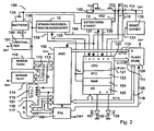
- the FIG. 2 shows a block diagram of the postal security module PSM 100 in a preferred variant.
- the negative pole of the battery 134 is connected to ground and a pin P23 of the contact group 102.
- the positive pole of the battery 134 is connected to the one input of the voltage changeover switch 180 via the line 193, and the system voltage leading line 191 is connected to the other input of the voltage changeover switch 180.
- battery 134 is the type SL-389 / P for a lifetime up to 3.5 years or the type SL-386 / P for a lifetime up to 6 years with a maximum power consumption by the PSM 100 is suitable as a voltage switch 180, a commercial circuit of the type ADM 8693ARN be used.
- the output of the voltage changeover switch 180 is connected via the line 136 to a voltage monitoring unit 12 and a detection unit 13.
- the voltage monitoring unit 12 and the detection unit 13 communicate with the pins 1, 2, 4 and 5 of the processor 120 via the lines 135, 164 and 137, 139 in communication.
- the output of the Voltage switch 180 also connects via line 136 to the supply input of a first memory SRAM, which through the existing battery 134, becomes non-volatile memory NVRAM 116 of a first technology.
- the security module communicates with the postage meter via the system bus 115, 117, 118.
- the processor 120 may communicate via the system bus and a modem 83 in communication with a remote data center.
- Billing is completed by the ASIC 150.
- the postal billing data is stored in non-volatile memory of different technology.
- a second memory NV-RAM 114 system voltage is applied.
- This second technology preferably comprises a RAM and an EEPROM, the latter automatically assuming the data contents in the event of system voltage failure.
- the NVRAM 114 of the second technology is connected to the corresponding address and data inputs of the ASIC 150 via an internal address and data bus 112, 113.
- the ASIC 150 contains at least one hardware abort unit for the calculation of the postal data to be stored.
- the Programmable Array Logic (PAL) 160 accommodates access logic for the ASIC 150.
- the ASIC 150 is controlled by the PAL 160 logic.
- An address and control bus 117, 115 from the motherboard of the meter 1 is connected to corresponding pins of the PAL 160 logic and the PAL 160 generates at least one control signal for the ASIC 150 and a control signal 119 for the program memory FLASH 128.
- the processor 120 operates Program stored in the FLASH 128.
- Processor 120, FLASH 28, ASIC 12, and PAL 160 are interconnected via a module-internal system bus, which includes lines 110, 11, 12, 126, 119 for data, address, and control signals.
- the RESET unit 130 is connected via the line 131 to the pin 3 of the processor 120 and to a pin of the ASIC 150.
- the processor 120 and the ASIC 150 are reset by a reset generation in the RESET unit 130 when the supply voltage drops.
- the processor 120 internally comprises a processing unit CPU 121, a real time clock RTC 122, a RAM unit 124, and an input / output unit 125.
- the processor 120 of the security module 100 is connected via a module internal data bus 126 to a FLASH 128 and to the ASIC 150 connected.
- the FLASH 128 serves as program memory and is supplied with system voltage Us +. For example, it is a 128 Kbyte FLASH memory type AM29F010-45EC.
- the ASIC 150 of the postal security module 100 supplies addresses 0 to 7 to the corresponding address inputs of the FLASH 128 via a module-internal address bus 110.
- the processor 120 of the security module 100 delivers the addresses 8 to 15 to the corresponding address inputs of the FLASH 128 via an internal address bus 111
- the ASIC 150 of the security module 100 is in communication via the contact group 101 of the interface with the data bus 118, with the address bus 117 and the control bus 115 of the mainboard of the meter 1.
- Voltage selector 180 as output voltage on line 136 for voltage monitor 12 and memory 116, forwards that of its input voltages which is greater than the other. Due to the possibility of automatically feeding the described circuit as a function of the magnitude of the voltages Us + and Ub + with the larger of the two, during normal operation the battery 134 can be exchanged without loss of data.
- the real-time clock RTC 122 and the memory RAM 124 are supplied by an operating voltage via the line 138. This voltage is generated by the voltage monitoring unit 12.
- the real-time clock 122 with date and / or time registers and / or the static RAM (SRAM) 124 which holds security-related data.
- circuit 12 connects the feed point for RTC and SRAM to ground. This means that the voltage at the RTC and the SRAM is then at 0V.
- the SRAM 124 which contains eg important cryptographic keys, is deleted very quickly.
- the registers of RTC 122 are cleared and the current time and date are lost. This action prevents a potential attacker from manipulating the battery voltage franking machine internal clock 122 stops without loss of security-relevant data. This prevents it from bypassing security measures such as long-time watchdogs.
- the circuit of the voltage monitoring unit 12 is dimensioned so that any drop in the battery voltage on the line 136 below the specified threshold of 2.6 V will cause the circuit 12 to respond. Simultaneously with the indication of the undervoltage of the battery, the circuit 12 changes into a self-holding state in which it remains even when subsequently increasing the voltage. It also provides a status signal 164. The next time the module is switched on, the processor can query the state of the circuit (status signal) and thus and / or via the evaluation of the contents of the erased memory, indicate that the battery voltage has in the meantime fallen below a certain value. The processor may reset the monitoring circuit 12, i. "make sharp. The latter responds to a control signal on line 135.
- the line 136 at the input of the battery top 12 also supplies a detection unit 13 with operating or battery voltage.
- the detection unit 13 may monitor an unplugged sensor or any other sensor and has a latch which is resettable by the processor.
- the state (is latching or not triggered) of the detection unit 13 is queried by the processor 120 via the line 139 or the detection unit 13 is triggered or reset by the processor 120 via the line 137. After reset, a static check for connection is made.
- ground potential is queried via a line 192, which is present at terminal P4 of the interface of the postal security module PSM 100 and can only be interrogated if the security module 100 is inserted correctly.
- ground potential of the negative pole 104 of the battery 134 of the postal security module PSM 100 is placed on the port P23 of the interface with the contact group 102 and thus at port P4 of the interface via the line 192 of the detection unit 13 queried.
- the processor 120 is equipped with the input / output unit 125, whose terminals are pins 8, 9 for outputting at least one signal for signaling the state of the security module 100.
- the input / output unit 125 At the pins 8 and 9 are I / O ports of the input / output unit 125, to which module-internal signaling means are connected, for example, colored light emitting diode LED's 107, 108.
- module-internal signaling means for example, colored light emitting diode LED's 107, 108.
- These signal the module state at a stuck on the motherboard of the meter 1 security module 100th through an opening 109 in the meter housing.
- the safety modules can assume different states in their life cycle. So, for example, to detect whether the module contains valid cryptographic keys. Furthermore, it is also important to distinguish whether the module is working or is defective. The exact type and number of module states depends on the implemented functions in the module and on the implementation.
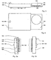
- the FIG. 3 shows shows the mechanical structure of the security module according to a first variant in side view.
- the security module is designed as a multi-chip module, that is, a plurality of functional units are interconnected on a printed circuit board 106.
- the security module 100 is potted with a hard potting compound 105, wherein the battery 134 of the security module 100 is arranged outside of the potting compound 105 on a printed circuit board 106 interchangeable.
- it is potted with a potting material 105 that the signal means 107, 108 protrudes from the potting material at a first location and that the circuit board 106 projects with the inserted battery 134 laterally of a second location.
- the printed circuit board 106 also has battery contact terminals 103 and 104 for connecting the poles of the battery 134, preferably on the component side above the printed circuit board 106. It is envisaged that for plugging the postal security module PSM 100 on the main board of the meter 1, the contact groups 101 and 102nd are arranged below the circuit board 106 (trace side) of the security module 100. For example, a contact group is used 101 for communication of the security module 100 with the meter 1 and a second contact group 102 serves to supply the security module 100 with the system voltage, wherein at least one of the contact groups 101, 102 is surrounded on one side by the potting material 105.
- the user circuit ASIC 150 is via the first contact group 101 - in a manner not shown - in communication with the system bus of a control device 1 and the second contact group 102 serves to supply the security module 100 with the system voltage.
- the security module is plugged onto the motherboard, then it is preferably arranged within the meter housing in such a way that the signal means 107, 108 near an opening 109 or projects into this.
- the meter housing is thus advantageously designed so that the user can still see the status of the security module from the outside.
- the two light emitting diodes 107 and 108 of the signal means are controlled via two output signals of the I / O ports to the pin 8, 9 of the processor 120.
- Both LEDs are housed in a common component housing (Bicolorleuchtdiode), which is why the dimensions or the diameter of the opening can remain relatively small and is in the order of magnitude of the signaling means.
- a common component housing Bocolorleuchtdiode
- three different colors can be displayed (red, green, orange), but of which only two are used (red and green).
- red and green To distinguish the state of the LEDs are also flashing controlled, so that five different state groups can be distinguished, which are characterized by the following LED states: LED off, red LED flashing, red LED, green flashing LED, green LED.
- FIG. 4 is a plan view of the postal security module of the first variant shown.
- the potting compound 105 surrounds a first part of the circuit board 106 in a cuboid, while a second part of the circuit board 106 for the replaceably arranged battery 134 remains free of potting compound.
- the battery contact terminals 103 and 104 are here covered by the battery, but are again in the side view Fig. 5a visible, noticeable.
- FIGS. 5a or 5b show a view of the security module of the first variant respectively from the right and from the left.
- the location of the contact groups 101 and 102 below the printed circuit board 106 is from the FIGS. 5a and 5b combined with FIG. 3 more visible.
- the signal means 107, 108 is preferably in the first part of the printed circuit board 106 connected, which is surrounded by the potting material 105 ( FIGS. 3, 4 and 5b ). For energy saving reasons, only when the safety module is supplied with system voltage does the signaling of the module status take place.
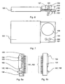
- FIG. 6 shows shows the mechanical structure of the security module according to a second variant in side view.
- the security module is again designed as a multi-chip module and potted with a hard potting compound 105, wherein the battery 134 of the security module 100 is arranged outside of the potting compound 105 on a printed circuit board 106 interchangeable.
- the potting is performed at a first location with a potting material 105 that the signal means 107, 108 and the inserted battery 134 are mounted externally from the potting material at a second location on the top of the circuit board 106.
- the circuit board 106 has again battery contact terminals 103 and 104 for connecting the poles of the battery 134, preferably on the component side above the circuit board 106.
- the two LEDs 107 and 108 of the signal means are separate components in this variant.
- the two light emitting diodes 107 and 108 of the signal means are controlled via two output signals of the I / O ports to the pin 8, 9 of the processor 120.
- the LEDs can in turn also be controlled flashing so that at least five different state groups can be distinguished, which are characterized, for example, by the following LED states: LED 107, 108 both off, LED 107 flashing red, LED 107 flashing red, LED 108 green flashing, LED 108 lit green.
- the meter housing is also designed again so that the user can see the status display of the security module from the outside, for example through a viewing window or opening 109.
- a connector 127 includes the contact groups 101 and 102, wherein the connector 127 is disposed on the wiring side of the circuit board 106.
- FIG. 7 is a plan view of the postal security module of the second variant shown.
- the potting compound 105 surrounds the first part of the circuit board 106 in a cuboid, while the second part of the circuit board 106 for the two light emitting diodes 107 and 108, the interchangeably arranged battery 134 and the connector 127 (not visible here) remains free of potting compound.
- the battery contact terminals 103 and 104 are in the FIG. 7 covered by the battery, but as well as the connector 127 in the side view after Figure 8a visible, noticeable.
- the potting of the first part of the circuit board 106 shows neither openings nor elevations and thus offers fewer points of attack for manipulation in criminal intent.
- the potting material 105 is preferably a two-component epoxy resin or polymer or plastic. Suitable is a potting compound from STYCAST®2651-40 FR from EMERSON & CUMING with preferably CATALYST 9 as the second component.
- both components are mixed and applied to both sides of the circuit board 106 in the first part. The latter can be done for example by immersion in the fresh mixture.
- a protection layer and / or sensor layer which is not visible from the outside after a final external encapsulation, can be applied, which forms a firm connection with the latter during hardening of the encapsulation material 105.
- the potting compound hardens to the solid opaque potting material 105.
- FIGS. 8a and FIG. 8b show a view of the security module of the second variant respectively from the right and from the left.
- the position of the connector 127 with the contact groups 101 and 102 below the circuit board 106 is from the FIGS. 8a and 8b combined with FIG. 6 more visible.
- a connector 127 may be mounted on top of the second part of the circuit board 106, not shown.
- the postal device in particular a franking machine
- the security module can also have a different design, which makes it possible, for example, it can be plugged into the motherboard of a personal computer, which drives a commercial printer as a PC meter.
Landscapes
- Physics & Mathematics (AREA)
- General Physics & Mathematics (AREA)
- Devices For Checking Fares Or Tickets At Control Points (AREA)
- Charge And Discharge Circuits For Batteries Or The Like (AREA)
- Storage Device Security (AREA)
- Alarm Systems (AREA)
- Mobile Radio Communication Systems (AREA)
- Battery Mounting, Suspending (AREA)
Description
- Die Erfindung betrifft ein Sicherheitsmodul mit Statussignalisierung, gemäß der im Oberbegriff des Patentanspruchs 1 angegebenen Art. Ein solcher postalischer Sicherheitsmodul ist insbesondere für den Einsatz in einer Frankiermaschine bzw. Postbearbeitungsmaschine oder Computer mit Postbearbeitungsfunktion geeignet.
- Moderne Frankiermaschinen, oder andere Einrichtungen zum Frankieren von Postgut, sind mit einem Drucker zum Drucken des Postwertstempels auf das Postgut, mit einer Steuerung zum Steuern des Druckens und der peripheren Komponenten der Frankiermaschine, mit einer Abrecheneinheit zum Abrechnen von Postgebühren, die in nichtflüchtigen Speichern gehalten werden, und einer Einheit zum kryptografischen Absichern der Postgebührendaten ausgestattet. Die Abrecheneinheit und/oder die Einheit zum Absichern des Druckens der Postgebührendaten kann von einem sogenannten Sicherheitsmodul realisiert werden (
EP 789 333 A2 - Der Prozessor des Sicherheitsmoduls ist beispielsweise ein OTP (One Time Programmable), welcher sensible Daten, wie kryptografische Schlüssel, auslesesicher speichert. Die Kapselung durch ein Sicherheitsgehäuse bietet einen weiteren Schutz.
- Sicherheitsmodule sind auch von anderen elektronischen Datenverarbeitungsanlagen bereits bekannt und mit Mitteln zum Schutz vor einem Einbruch in ihre Elektronik ausgestattet (
EP 417 447 B1 - Weitere Maßnahmen zum Schutz eines Sicherheitsmoduls vor einem Angriff auf die in ihm gespeicherten Daten wurden auch in den nicht vorveröffentlichten
deutschen Anmeldungen 198 16 572.2 und198 16 571.4 vorgeschlagen. Bei einer Vielzahl von Sensoren steigt der Stromverbrauch und ein nicht ständig von einer Systemspannung versorgter Sicherheitsmodul zieht dann den für die Sensoren benötigten Strom aus seiner internen Batterie, was letztere ebenfalls frühzeitig erschöpft. Die Kapazität der Batterie und der Stromverbrauch beschränken somit die Lebensdauer eines Sicherheitsmoduls. - Sicherheitsmodule für Frankiermaschinen können als Multi-Chip-Module oder als Ein-Chip-Systeme (z.B. Chipkarten) realisiert werden. Sie sind konstruktiv entweder fest mit der Frankiermaschine verbunden oder steckbar. Gerade ein steckbares Sicherheitsmodul kann in seinem Lebenszyklus verschiedene Zustände einnehmen. Dabei muß detektiert werden, ob das Sicherheitsmodul gültige kryptografische Schlüssel enthält. Weiterhin ist es auch wichtig zu unterscheiden, ob das Sicherheitsmodul funktioniert oder defekt ist. Nachteilig ist, dass dafür ein geeignetes "Zustandslesegerät", beispielsweise eine Frankiermaschine oder ein anderes Gerät vorhanden sein muß. Letzteres kann unter Umständen zu einer manipulierten falschen Zustandssignalisierung veranlaßt werden. Existierende Sicherheitsmodule für Frankiermaschinen besitzen keine eigenen optischen oder akustischen Signalmittel. Sie können ihren Zustand nur indirekt, beispielsweise über Beeper oder die Anzeigeelemente einer Frankiermaschine, ausgeben. Die Zustandsanzeige kann hierbei automatisch beim Starten des Systems oder interaktiv durch den Benutzter der Frankiermaschine aufgerufen werden, wenn die Sicherheit bei der Signalisierung eines Zustandes garantiert werden kann.
- Die
EP 0 649 080 zeigt ein Verfahren zur Sicherung sicherheitsrelevanter Informationen in einem mit einer zentralen Datenverarbeitungsanlage gekoppelten Sicherheitsmodul eines Terminals. - Der Erfindung liegt die Aufgabe zugrunde, für ein steckbares Sicherheitsmodul eine hohe Lebensdauer zu erzielen und es zur sicheren Signalisierung des Modulzustandes auszubilden.
- Die Aufgabe wird mit den Merkmalen des Patentanspruchs 1 gelöst.
- Die Schaltung mit dem Prozessor des Sicherheitsmoduls, der auslesesicher sensible Daten enthält, und weiteren Funktionseinheiten werden lediglich durch eine Vergußmasse geschützt. Deshalb wird die Hauptplatine eines Meters bzw. einer vergleichbaren Steuereinrichtung mit einem Sicherheitsgehäuse umgeben, welches ggf. zusätzlich versiegelt ist. Das Sicherheitsmodul ist mit einer harten Masse vergossen. Für einen Batteriewechsel bzw. Entsorgung ist die Batterie jedoch außerhalb der Vergußmasse angeordnet. In vorteilhafter Weise kann bei einem gestecktem Sicherheitsmodul, welches zum Servicezeitpunkt von einer Systemspannung versorgt wird, die Batterie von einem Servicetechniker leicht ausgewechselt werden.
- Es ist beim erfindungsgemäßen Sicherheitsmodul vorteilhaft, wenn letzteres selbstständig - bei Anlegen der Betriebsspannung - optisch (oder akustisch) seinen Zustand signalisiert. Es ist hierbei möglich und auch ausreichend, wenn das Modul nur ein grobe Unterscheidung des aktuellen Zustands durch eigene Signalmittel zuläßt. Die genaue Art und Anzahl der Modulzustände ist von den realisierten Funktionen im Modul und von der Implementierung abhängig.
- Das Sicherheitsmodul für eine Frankiermaschine nimmt deren Funktion einer Abrechnung der Postgebühren und/oder die kryptografische Absicherung der Postgebührendaten war. Es ist erfindungsgemäß durch eigene Signalmittel oder eine Anzeigeeinheit gekennzeichnet, die bei direkter Ansteuerung vom Sicherheitsmodul eine Aussage über den aktuellen Zustand des Sicherheitsmoduls gestatten, wobei der Modulzustand geändert wird, wenn das Sicherheitsmodul in den ungesteckten Zustand überführt wird und/oder wenn die Batteriespannung unter eine vorbestimmte Schwelle sinkt, die jedoch bei Versorgung des Sicherheitsmoduls mit Systemspannung unterbrochen ist. Die Signalisierung des Modulzustandes wird nur bei Versorgung des Sicherheitsmoduls mit Systemspannung aktiviert. Es ist vorgesehen, dass das Signalmittel in demjenigen Bereich einer Leiterplatte des Sicherheitsmoduls montiert ist, wo das umgebende Sicherheitsgehäuse zur Signalisierung des Modulzustandes ein Sichtfenster bzw. eine Öffnung aufweist. Das Signalmittel ist vorteilhaft als Anzeigeeinheit realisiert und kann im einfachsten Fall eine Leuchtdiode LED sein. Sie kann durch das Vergußmaterial hindurchragen. Alternativ oder zusätzlich sind mehrere oder mehrfarbige LED's oder eine Flüssigkristallanzeige LCD o.a. Signalmittel möglich, die am von Vergußmaterial freien Teil der Leiterplatte angeordnet sind.
- Vorteilhafte Weiterbildungen der Erfindung sind in den Unteransprüchen gekennzeichnet bzw. werden nachstehend zusammen mit der Beschreibung der bevorzugten Ausführung der Erfindung anhand der Figuren näher dargestellt. Es zeigen:
-
Figur 1 , Perspektivische Ansicht der Frankiermaschine von hinten, -
Figur 2 , Blockschaltbild des Sicherheitsmoduls, -
Figur 3 , Seitenansicht einer ersten Variante des Sicherheitsmoduls, -
Figur 4 , Draufsicht auf das Sicherheitsmodul in der ersten Variante, -
Figur 5a , Ansicht des Sicherheitsmoduls (1 .Variante) von rechts, -
Figur 5b , Ansicht des Sicherheitsmoduls (1 .Variante) von links, -
Figur 6 , Seitenansicht einer zweiten Variante des Sicherheitsmoduls, -
Figur 7 , Draufsicht auf das Sicherheitsmodul in der zweiten Variante, -
Figur 8a , Ansicht des Sicherheitsmoduls (2.Variante) von rechts, -
Figur 8b , Ansicht des Sicherheitsmoduls (2.Variante) von links. - In der
Figur 1 ist eine perspektivische Ansicht der Frankiermaschine von hinten dargestellt. Die Frankiermaschine besteht aus einem Meter 1 und einer Base 2. Letztere ist mit einer Chipkarten-Schreib/ Leseeinheit 70 ausgestattet, die hinter der Führungsplatte 20 angeordnet und von der Gehäuseoberkante 22 zugänglich ist. Nach dem Einschalten der Frankiermaschine mittels dem Schalter 71 wird eine Chipkarte 49 von oben nach unten in den Einsteckschlitz 72 eingesteckt. Ein zugeführter auf der Kante stehender Brief 3, der mit seiner zu bedruckenden Oberfläche an der Führungsplatte anliegt, wird dann entsprechend der Eingabedaten mit einem Frankierstempel 31 bedruckt. Die Briefzuführöffnung wird durch eine Klarsichtplatte 21 und die Führungsplatte 20 seitlich begrenzt. - Das Modul wird auf die Hauptplatine des Meters der Frankiermaschine oder eines anderen geeigneten Gerätes gesteckt. Es ist vorzugsweise innerhalb des Metergehäuses untergebracht, welches als Sicherheitsgehäuse ausgebildet ist. Das Metergehäuse ist dabei vorteilhaft so konstruiert, daß der Benutzer die Statusanzeige des Sicherheitsmoduls trotzdem von außen durch eine Öffnung 109 sehen kann, wobei sich die Öffnung 109 zur Bedienoberfläche 88, 89 des Meters 1 erstreckt.
- Die Anzeige wird direkt vom modulinternen Prozessor gesteuert und ist so von außen nicht ohne weiteres manipulierbar. Die Anzeige ist im Betriebszustand ständig aktiv, so daß das Anlegen der Systemspannung Us+ an den Prozessor des Sicherheitsmoduls ausreicht, die Anzeige zu aktivieren, um den Modulzustand ablesen zu können.
- Die
Figur 2 zeigt ein Blockschaltbild des postalischen Sicherheitsmoduls PSM 100 in einer bevorzugten Variante. Der negative Pol der Batterie 134 ist auf Masse und einen Pin P23 der Kontaktgruppe 102 gelegt. Der positive Pol der Batterie 134 ist über die Leitung 193 mit dem einen Eingang des Spannungsumschalters 180 und die Systemspannung führende Leitung 191 ist mit dem anderen Eingang des Spannungsumschalters 180 verbunden. Als Batterie 134 eignet sich der Typ SL-389/P für eine Lebensdauer bis zu 3,5 Jahren oder der Typ SL-386/P für eine Lebensdauer bis zu 6 Jahren bei einem maximalen Stromverbrauch durch das PSM 100. Als Spannungsumschalter 180 kann ein handelsüblicher Schaltkreis vom Typ ADM 8693ARN eingesetzt werden. Der Ausgang des Spannungsumschalters 180 liegt über die Leitung 136 an einer Spannungsüberwachungseinheit 12 und einer Detektionseinheit 13 an. Die Spannungsüberwachungseinheit 12 und die Detektionseinheit 13 stehen mit den Pins 1, 2, 4 und 5 des Prozessors 120 über die Leitungen 135, 164 und 137, 139 in Kommunikationsverbindung. Der Ausgang des Spannungsumschalters 180 liegt über die Leitung 136 außerdem am Versorgungseingang eines ersten Speichers SRAM an, der durch die vorhandene Batterie 134 zum nichtflüchtigen Speicher NVRAM 116 einer ersten Technologie wird. - Das Sicherheitsmodul steht mit der Frankiermaschine über den Systembus 115,117, 118 in Verbindung. Der Prozessor 120 kann über den Systembus und ein Modem 83 in Kommunikationsverbindung mit einer entfernten Datenzentrale eintreten. Die Abrechnung wird vom ASIC 150 vollzogen. Die postalischen Abrechnungsdaten werden in nichtflüchtigen Speichern unterschiedlicher Technologie gespeichert. Am Versorgungseingang eines zweiten Speichers NV-RAM 114 liegt Systemspannung an. Hierbei handelt es sich um einen nichtflüchtigen Speicher NVRAM einer zweiten Technologie, (SHADOW-RAM). Diese zweiten Technologie umfaßt vorzugsweise ein RAM und ein EEPROM, wobei letzteres die Dateninhalte bei Systemspannungsausfall automatisch übernimmt. Der NVRAM 114 der zweiten Technologie ist mit den entsprechenden Adress- und Dateneingängen des ASIC's 150 über einen internen Adreß- und Datenbus 112, 113 verbunden.
- Der ASIC 150 enthält mindestens eine Hardware-Abrecheneinheit für die Berechnung der zu speichernden postalischen Daten. In der Programmable Array Logic (PAL) 160 ist eine Zugriffslogik für den ASIC 150 untergebracht. Der ASIC 150 wird durch die Logik PAL 160 gesteuert. Ein Adreß- und Steuerbus 117, 115 von der Hauptplatine des Meters 1 ist an entsprechenden Pins der Logik PAL 160 angeschlossen und die PAL 160 erzeugt mindestens ein Steuersignal für das ASIC 150 und ein Steuersignal 119 für den Programmspeicher FLASH 128. Der Prozessor 120 arbeitet ein Programm ab, das im FLASH 128 gespeichert ist. Der Prozessor 120, FLASH 28, ASIC 12 und PAL 160 sind über einen modulinternen Systembus miteinander verbunden, der Leitungen 110,111,126,119 für Daten-, Adreß- und Steuersignale enthält.
- Die RESET-Einheit 130 ist über die Leitung 131 mit dem Pin 3 des Prozessors 120 und mit einem Pin des ASIC's 150 verbunden. Der Prozessor 120 und das ASIC 150 werden bei Absinken der Versorgungsspannung durch eine Resetgenerierung in der RESET-Einheit 130 zurückgesetzt.
- Der Prozessor 120 weist intern eine Verarbeitungseinheit CPU 121, eine Echtzeituhr RTC 122 eine RAM-Einheit 124 und eine Ein/Ausgabe-Einheit 125 auf Der Prozessor 120 des Sicherheitsmoduls 100 ist über einen modul-internen Datenbus 126 mit einem FLASH 128 und mit dem ASIC 150 verbunden. Der FLASH 128 dient als Programmspeicher und wird mit Systemspannung Us+ versorgt. Er ist beispielsweise ein 128 Kbyte-FLASH-Speicher vom Typ AM29F010-45EC. Der ASIC 150 des postalischen Sicherheitsmoduls 100 liefert über einen modulinternen Adreßbus 110 die Adressen 0 bis 7 an die entsprechenden Adreßeingänge des FLASH 128. Der Prozessor 120 des Sicherheitsmoduls 100 liefert über einen internen Adreßbus 111 die Adressen 8 bis 15 an die entsprechenden Adresseingänge des FLASH 128. Der ASIC 150 des Sicherheitsmoduls 100 steht über die Kontaktgruppe 101 des Interfaces mit dem Datenbus 118, mit dem Adreßbus 117 und dem Steuerbus 115 der Hauptplatine des Meters 1 in Kommunikationsverbindung.
- Der Spannungsumschalter 180 gibt als Ausgangsspannung auf der Leitung 136 für die Spannungsüberwachungseinheit 12 und Speicher 116 diejenige seiner Eingangsspannungen weiter, die größer als die andere ist. Durch die Möglichkeit, die beschriebene Schaltung in Abhängigkeit von der Höhe der Spannungen Us+ und Ub+ automatisch mit der größeren von beiden zu speisen, kann während des Normalbetriebs die Batterie 134 ohne Datenverlust gewechselt werden. Die Echtzeituhr RTC 122 und der Speicher RAM 124 werden von einer Betriebsspannung über die Leitung 138 versorgt. Diese Spannung wird von der Spannungsüberwachungseinheit 12 erzeugt.
- Die Batterie der Frankiermaschine speist in den Ruhezeiten außerhalb des Normalbetriebes in vorerwähnter Weise die Echtzeituhr 122 mit Datums und/oder Uhrzeitregistern und/oder den statischen RAM (SRAM) 124, der sicherheitsrelevante Daten hält. Sinkt die Spannung der Batterie während des Batteriebetriebs unter eine bestimmte Grenze, so wird von der Schaltung 12 der Speisepunkt für RTC und SRAM mit Masse verbunden. D.h. die Spannung an der RTC und am SRAM liegt dann bei 0V. Das führt dazu, daß der SRAM 124, der z.B. wichtige kryptografische Schlüssel enthält, sehr schnell gelöscht wird. Gleichzeitig werden auch die Register der RTC 122 gelöscht und die aktuelle Uhrzeit und das aktuelle Datum gehen verloren. Durch diese Aktion wird verhindert, daß ein möglicher Angreifer durch Manipulation der Batteriespannung die frankiermaschineninterne Uhr 122 anhält, ohne daß sicherheitsrelevante Daten verloren gehen. Somit wird verhindert, daß er Sicherheitsmaßnahmen, wie beispielsweise Long Time Watchdogs umgeht.
- Die Schaltung der Spannungsüberwachungseinheit 12 ist beispielsweise so dimensioniert, daß jegliches Absinken der Batteriespannung auf der Leitung 136 unter die spezifizierte Schwelle von 2,6 V zum Ansprechen der Schaltung 12 führt. Gleichzeitig mit der Indikation der Unterspannung der Batterie wechselt die Schaltung 12 in einen Selbsthaltezustand, in dem sie auch bei nachträglicher Erhöhung der Spannung bleibt. Sie liefert außerdem ein Statussignal 164. Beim nächsten Einschalten des Moduls kann der Prozessor den Zustand der Schaltung abfragen (Statussignal) und damit und/oder über die Auswertung der Inhalte des gelöschten Speichers darauf schließen, daß die Batteriespannung zwischenzeitlich einen bestimmten Wert unterschritten hat. Der Prozessor kann die Überwachungsschaltung 12 zurücksetzen, d.h. "scharf" machen. Letztere reagiert auf ein Steuersignal auf der Leitung 135.
- Die Leitung 136 am Eingang des Batterieobservers 12 versorgt zugleich eine Detektions-Einheit 13 mit Betriebs- oder Batteriespannung. Die Detektions-Einheit 13 kann ein Ungestecktsein-Sensor oder irgend einen anderen Sensor überwachen und hat eine Selbsthaltung, welche vom Prozessor rücksetzbar ist. Der Zustand (ist Selbsthaltung oder nicht ausgelöst) der Detektions-Einheit 13 wird vom Prozessor 120 über die Leitung 139 abgefragt oder die Detektions-Einheit 13 wird vom Prozessor 120 über die Leitung 137 ausgelöst bzw. rückgesetzt. Nach dem Rücksetzen wird eine statische Prüfung auf Anschluß durchgeführt. Dazu wird über eine Leitung 192 Massepotential abgefragt, welches am Anschluß P4 des Interfaces des postalischen Sicherheitsmoduls PSM 100 anliegt und nur abfragbar ist, wenn der Sicherheitsmodul 100 ordnungsgemäß gesteckt ist. Bei gesteckten Sicherheitsmodul 100 wird Massepotential des negativen Pols 104 der Batterie 134 des postalischen Sicherheitsmoduls PSM 100 auf den Anschluß P23 des Interfaces mit der Kontaktgruppe 102 gelegt und ist somit am Anschluß P4 des Interfaces über die Leitung 192 von der Detektions-Einheit 13 abfragbar.
- An den Pins 6 und 7 des Prozessors 120 sind Leitungen angeschlossen, welche nur bei einem, beispielsweise an die Hauptplatine des Meters 1, gesteckten Sicherheitsmodul 100 eine Leiterschleife 18 bilden. Zur dynamischen Prüfung des Angeschlossenseins des postalischen Sicherheitsmoduls PSM 100 an der Hauptplatine des Meters 1 werden vom Prozessor 120 wechselnde Signalpegel in ganz unregelmäßigen Zeitabständen an die Pin's 6, 7 angelegt und über die Schleife zurückgeschleift.
- Der Prozessor 120 ist mit der Ein/Ausgabe-Einheit 125 ausgestattet, deren Anschlüsse Pin's 8, 9 zur Ausgabe mindestens eines Signals zur Signalisierung des Zustandes des Sicherheitsmoduls 100 dienen. An den Pin's 8 und 9 liegen I/O-Ports der Ein/Ausgabe-Einheit 125, an welchen modulinterne Signalmittel angeschlossen sind, beispielsweise farbige Lichtemitterdioden LED's 107, 108. Diese signalisieren den Modulzustand bei einem auf die Hauptplatine des Meters 1 gesteckten Sicherheitsmoduls 100 durch eine Öffnung 109 im Metergehäuse. Die Sicherheitsmodule können in ihrem Lebenszyklus verschiedene Zustände einnehmen. So muß z.B. detektiert werden, ob das Modul gültige kryptografische Schlüssel enthält. Weiterhin ist es auch wichtig zu unterscheiden, ob das Modul funktioniert oder defekt ist. Die genaue Art und Anzahl der Modulzustände ist von den realisierten Funktionen im Modul und von der Implementierung abhängig.
- Die
Figur 3 zeigt zeigt den mechanischen Aufbau des Sicherheitsmoduls nach einer ersten Variante in Seitenansicht. Das Sicherheitsmodul ist als Multi-Chip-Modul ausgebildet, d.h. mehrere Funktionseinheiten sind auf einer Leiterplatte 106 verschaltet. Das Sicherheitsmodul 100 ist mit einer harten Vergußmasse 105 vergossen, wobei die Batterie 134 des Sicherheitsmoduls 100 außerhalb der Vergußmasse 105 auf einer Leiterplatte 106 auswechselbar angeordnet ist. Beispielsweise ist es so mit einem Vergußmaterial 105 vergossen, daß das Signalmittel 107, 108 aus dem Vergußmaterial an einer ersten Stelle herausragt und daß die Leiterplatte 106 mit der gesteckten Batterie 134 seitlich einer zweiten Stelle herausragt. Die Leiterplatte 106 hat außerdem Batteriekontaktklemmen 103 und 104 für den Anschluß der Pole der Batterie 134, vorzugsweise auf der Bestückungsseite oberhalb der Leiterplatte 106. Es ist vorgesehen, daß zum Anstecken des postalischen Sicherheitsmoduls PSM 100 auf die Hauptplatine des Meters 1 die Kontaktgruppen 101 und 102 unterhalb der Leiterplatte 106 (Leiterbahnseite) des Sicherheitsmoduls 100 angeordnet sind. Beispielsweise dient eine Kontaktgruppe 101 zur Kommunikation des Sicherheitsmoduls 100 mit dem Meter 1 und eine zweite Kontaktgruppe 102 dient zur Versorgung des Sicherheitsmoduls 100 mit der Systemspannung, wobei mindestens eine der Kontaktgruppen 101, 102 einseitig durch das Vergußmaterial 105 umgeben ist. Der Anwenderschaltkreis ASIC 150 steht über die erste Kontaktgruppe 101 - in nicht gezeigter Weise - mit dem Systembus einer Steuereinrichtung 1 in Kommunikationsverbindung und die zweite Kontaktgruppe 102 dient der Versorgung des Sicherheitsmoduls 100 mit der Systemspannung. Wird das Sicherheitsmodul auf die Hauptplatine gesteckt, dann ist es vorzugsweise innerhalb des Metergehäuses dergestalt angeordnet, so daß das Signalmittel 107, 108 nahe einer Öffnung 109 ist oder in diese hineinragt. Das Metergehäuse ist damit vorteilhaft so konstruiert, daß der Benutzer die Statusanzeige des Sicherheitsmoduls trotzdem von außen sehen kann. Die beiden Leuchtdioden 107 und 108 des Signalmittels werden über zwei Ausgangssignale der I/O-Ports an den Pin 8, 9 des Prozessors 120 gesteuert. Beide Leuchtdioden sind in einem gemeinsamen Bauelementegehäuse untergebracht (Bicolorleuchtdiode), weshalb die Abmaße bzw. der Durchmesser der Öffnung relativ klein bleiben kann und in der Größenordnung des Signalmittels liegt.Prinzipiell sind drei unterschiedliche Farben darstellbar (rot, grün, orange), von denen aber nur zwei benutzt werden (rot und grün). Zur Zustandsunterscheidung werden die LED's auch blinkend gesteuert, so daß fünf verschiedene Zustandsgruppen unterschieden werden können, die durch folgende LED-Zustände charakterisiert werden: LED aus, LED rot blinkend, LED rot, LED grün blinkend, LED grün. - In der
Figur 4 ist eine Draufsicht auf das postalische Sicherheitsmodul der ersten Variante dargestellt. Die Vergußmasse 105 umgibt quaderförmig einen ersten Teil der Leiterplatte 106, während ein zweiter Teil der Leiterplatte 106 für die auswechselbar angeordnete Batterie 134 von Vergußmasse frei bleibt. Die Batteriekontaktklemmen 103 und 104 werden hier von der Batterie verdeckt, sind aber wieder in der Seitenansicht nachFig. 5a sichtbar. - Die
Figuren 5a bzw. 5b zeigen eine Ansicht des Sicherheitsmoduls der ersten Variante jeweils von rechts bzw. von links. Die Lage der Kontaktgruppen 101 und 102 unterhalb der Leiterplatte 106 wird aus denFiguren 5a und 5b in Verbindung mitFigur 3 deutlicher sichtbar. Das Signalmittel 107, 108 ist vorzugsweise im ersten Teil der Leiterplatte 106 angeschlossen, welches durch das Vergußmaterial 105 umgeben ist (Figuren 3, 4 und 5b ). Aus Energiespargründen erfolgt nur bei Versorgung des Sicherheitsmoduls mit Systemspannung die Signalisierung des Modulzustandes. - Die
Figur 6 zeigt zeigt den mechanischen Aufbau des Sicherheitsmoduls nach einer zweiten Variante in Seitenansicht. Das Sicherheitsmodul ist wieder als Multi-Chip-Modul ausgebildet und mit einer harten Vergußmasse 105 vergossen, wobei die Batterie 134 des Sicherheitsmoduls 100 außerhalb der Vergußmasse 105 auf einer Leiterplatte 106 auswechselbar angeordnet ist. Aus Kostengründen erfolgt der Verguß an einer ersten Stelle so mit einem Vergußmaterial 105, dass das Signalmittel 107, 108 und die gesteckte Batterie 134 extern vom Vergußmaterial an einer zweiten Stelle auf der Oberseite der Leiterplatte 106 montiert sind. Die Leiterplatte 106 hat wieder Batteriekontaktklemmen 103 und 104 für den Anschluß der Pole der Batterie 134, vorzugsweise auf der Bestückungsseite oberhalb der Leiterplatte 106. Die beiden Leuchtdioden 107 und 108 des Signalmittels sind bei dieser Variante separate Bauelemente. Die beiden Leuchtdioden 107 und 108 des Signalmittels werden über zwei Ausgangssignale der I/O-Ports an den Pin 8, 9 des Prozessors 120 gesteuert. Zur Zustandsunterscheidung können die LED's wiederum auch blinkend gesteuert werden, so dass mindestens fünf verschiedene Zustandsgruppen unterschieden werden können, die beispielsweise durch folgende LED-Zustände charakterisiert werden: LED 107, 108 beide aus, LED 107 rot blinkend, LED 107 rot leuchtend, LED 108 grün blinkend, LED 108 grün leuchtend. Das Metergehäuse ist ebenfalls wieder so konstruiert, daß der Benutzer die Statusanzeige des Sicherheitsmoduls von außen, beispielsweise durch ein Sichtfenster oder eine Öffnung 109 sehen kann. - Es ist ebenfalls vorgesehen, dass zum Anstecken des postalischen Sicherheitsmoduls PSM 100 auf die Hauptplatine des Meters 1 die Kontaktgruppen 101 und 102 unterhalb der Leiterplatte 106 des Sicherheitsmoduls 100 angeordnet sind. Vorteilhaft enthält ein Verbinder 127 die Kontaktgruppen 101 und 102, wobei der Verbinder 127 auf der Leiterbahnseite der Leiterplatte 106 angeordnet ist.
- In der
Figur 7 ist eine Draufsicht auf das postalische Sicherheitsmodul der zweiten Variante dargestellt. Die Vergußmasse 105 umgibt quaderförmig den ersten Teil der Leiterplatte 106, während der zweite Teil der Leiterplatte 106 für die beiden Leuchtdioden 107 und 108, die auswechselbar angeordnete Batterie 134 und für den Verbinder 127 (hier nicht sichtbar) frei von Vergußmasse bleibt. Die Batteriekontaktklemmen 103 und 104 werden in derFigur 7 von der Batterie verdeckt, sind aber ebenso wie der Verbinder 127 in der Seitenansicht nachFig.8a sichtbar. - Der Verguß des ersten Teils der Leiterplatte 106 zeigt weder Öffnungen noch Erhebungen und bietet somit weniger Angriffspunkte für ein Manipulation in krimineller Absicht. Das Vergußmaterial 105 ist vorzugsweise ein Zweikomponenten-Epoxitharz oder Polymer bzw. Kunststoff. Geeignet ist eine Vergußmasse aus STYCAST ®2651-40 FR von der Firma EMERSON & CUMING mit vorzugsweise CATALYST 9 als zweite Komponente. Bei der Herstellung des Vergusses werden beide Komponenten gemischt und auf beide Seiten der Leiterplatte 106 in deren ersten Teil aufgebracht. Letzteres kann beispielsweise durch Eintauchen in die frische Mischung erfolgen. Nun kann eine - nach einem abschließend äusserem Verguß von aussen nicht sichtbare - Schutz- und/oder Sensorschicht angebracht werden, welche während des Aushärtens des Vergußmaterials 105 mit letzterem eine feste Verbindung eingeht. Nach dem abschließenden äusseren Verguß härtet die Vergussmasse zu dem festen undurchsichtigen Vergußmaterials 105 aus.
- Die
Figuren 8a bzw. 8b zeigen eine Ansicht des Sicherheitsmoduls der zweiten Variante jeweils von rechts bzw. von links. Die Lage des Verbinders 127 mit den Kontaktgruppen 101 und 102 unterhalb der Leiterplatte 106 wird aus denFiguren 8a und 8b in Verbindung mitFigur 6 deutlicher sichtbar. - Alternativ kann beispielsweise ein Verbinder 127 - in nicht gezeigter Weise - auf der Oberseite des zweiten Teils der Leiterplatte 106 angebracht werden.
- Erfindungsgemäß ist das postalische Gerät, insbesondere eine Frankiermaschine, jedoch kann das Sicherheitsmodul auch eine andere Bauform aufweisen, die es ermöglicht, daß es beispielsweise auf die Hauptplatine eines Personalcomputers gesteckt werden kann, der als PC-Frankierer einen handelsüblichen Drucker ansteuert.
- Die Erfindung ist nicht auf die vorliegenden Ausführungsform beschränkt, da offensichtlich weitere andere Anordnungen bzw. Ausführungen der Erfindung entwickelt bzw. eingesetzt werden können, die - vom gleichen Grundgedanken der Erfindung ausgehend - von den anliegenden Schutzansprüchen umfaßt werden.
Claims (12)
- Sicherheitsmodul (100) mit Statussignalisierung, mit Funktionseinheiten, welche miteinander verschaltet und von einer Vergußmasse bedeckt sind,
gekennzeichnet dadurch,
daß die Vergußmasse (105) mindestens einen Teil der Leiterplatte (106) mit den verschalteten Funktionseinheiten umgibt, daß zur Signalisierung des Modulzustandes ein optisches oder akustisches Signalmittel (107, 108) an einer Funktionseinheit der Leiterplatte (106) angeschlossen ist, wobei die Signalisierung des Modulzustandes erfolgt, wenn am Sicherheitsmodul (100) eine Betriebsspannung anliegt. - Sicherheitsmodul (100), nach Anspruch 1, gekennzeichnet dadurch, daß Signalmittel (107, 108) im ersten Teil der Leiterplatte (106) in demjenigen Bereich durch das Vergußmaterial (105) hindurchragt, wo das umgebende Sicherheitsgehäuse eines Gerätes zur Signalisierung des Modulzustandes ein Sichtfenster oder eine Öffnung (109) aufweist.
- Sicherheitsmodul (100), nach Anspruch 1, gekennzeichnet dadurch, dass ein zweiter Teil der Leiterplatte (106) von Vergußmasse frei bleibt, daß Signalmittel (107, 108) im zweiten Teil der Leiterplatte (106) in demjenigen Bereich montiert ist, wo das umgebende Sicherheitsgehäuse eines Gerätes zur Signalisierung des Modulzustandes ein Sichtfenster oder eine Öffnung (109) aufweist.
- Sicherheitsmodul (100), nach den Ansprüchen 2 oder 3, gekennzeichnet dadurch, daß das Gerät ein Meter (1) ist und dass sich das Sichtfenster oder die Öffnung (109) zur Bedienoberfläche (88, 89) des Meters (1) erstreckt und daß die Abmaße bzw. der Durchmesser der Öffnung in der Größenordnung des Signalmittels liegen.
- Sicherheitsmodul (100), nach einem der Ansprüche 1 bis 4, gekennzeichnet dadurch, daß das Signalmittel als Anzeigeeinheit realisiert ist.
- Sicherheitsmodul (100), nach Anspruch 5, gekennzeichnet da- durch, daß die Anzeigeeinheit eine oder mehrere oder mehrfarbige Leuchtdioden (LED's) einschließt.
- Sicherheitsmodul (100), nach Anspruch 6, gekennzeichnet dadurch, daß die Leuchtdioden LED's zur Zustandsunterscheidung blinkend gesteuert werden.
- Sicherheitsmodul (100), nach Anspruch 5, gekennzeichnet dadurch, daß die Anzeigeeinheit eine Flüssigkristallanzeige (LCD) ist.
- Sicherheitsmodul (100), nach Anspruch 1, gekennzeichnet dadurch, daß ein zweiter Teil der Leiterplatte (106) für eine auswechselbar angeordnete Batterie (134) ausgebildet ist und von Vergußmasse frei bleibt, Batteriekontaktklemmen (103 und 104) für den Anschluß der Pole der Batterie (134) aufweist, daß die Leiterplatte (106) eine erste Kontaktgruppe (101 zur Kommunikation des Sicherheitsmoduls (100) mit dem Meter (1) und daß die Leiterplatte (106) eine zweite Kontaktgruppe (102) zur Versorgung des Sicherheitsmoduls (100) mit der Systemspannung aufweist, wobei der Modulzustandes geändert wird, wenn die Batteriespannung unter eine vorbestimmte Schwelle sinkt, wobei jedoch die Signalisierung des Modulzustandes nur bei Versorgung des Sicherheitsmoduls (100) mit Systemspannung aktiviert wird.
- Sicherheitsmodul, nach Anspruch 9, gekennzeichnet dadurch, dass mindestens eine der Kontaktgruppen (101, 102) einseitig durch das Vergußmaterial (105) umgeben ist.
- Sicherheitsmodul (100), nach Anspruch 9, gekennzeichnet dadurch, daß ein Verbinder (127) mit den Kontaktgruppen (101, 102) auf der Unterseite oder auf der Oberseite der Leiterplatte (106) angeordnet ist.
- Sicherheitsmodul (100), nach Anspruch 11, gekennzeichnet dadurch, daß ein Verbinder (127) mit den Kontaktgruppen (101, 102) auf der Unterseite oder auf der Oberseite der Leiterplatte (106) im zweiten Teil angeordnet ist, der frei von Vergußmaterial (105) ist.
Applications Claiming Priority (3)
| Application Number | Priority Date | Filing Date | Title |
|---|---|---|---|
| DE29905219U | 1999-03-12 | ||
| DE29905219U DE29905219U1 (de) | 1999-03-12 | 1999-03-12 | Sicherheitsmodul mit Statussignalisierung |
| US09/524,118 US6771179B1 (en) | 1999-03-12 | 2000-03-13 | Security module with status signaling |
Publications (3)
| Publication Number | Publication Date |
|---|---|
| EP1035513A2 EP1035513A2 (de) | 2000-09-13 |
| EP1035513A3 EP1035513A3 (de) | 2000-12-20 |
| EP1035513B1 true EP1035513B1 (de) | 2008-07-02 |
Family
ID=33300877
Family Applications (1)
| Application Number | Title | Priority Date | Filing Date |
|---|---|---|---|
| EP00250057A Expired - Lifetime EP1035513B1 (de) | 1999-03-12 | 2000-02-21 | Sicherheitsmodul mit Statussignalisierung |
Country Status (4)
| Country | Link |
|---|---|
| US (1) | US6771179B1 (de) |
| EP (1) | EP1035513B1 (de) |
| CN (1) | CN1151474C (de) |
| DE (1) | DE29905219U1 (de) |
Families Citing this family (10)
| Publication number | Priority date | Publication date | Assignee | Title |
|---|---|---|---|---|
| DE19928057B4 (de) | 1999-06-15 | 2005-11-10 | Francotyp-Postalia Ag & Co. Kg | Sicherheitsmodul und Verfahren zur Sicherung der Postregister vor Manipulation |
| DE19928061C2 (de) | 1999-06-15 | 2003-08-28 | Francotyp Postalia Ag | Sicherheitsmodul zur Überwachung der Systemsicherheit und Verfahren |
| DE19928058B4 (de) | 1999-06-15 | 2005-10-20 | Francotyp Postalia Ag | Anordnung und Verfahren zur Generierung eines Sicherheitsabdruckes |
| DE10003310A1 (de) | 2000-01-27 | 2001-08-02 | Francotyp Postalia Gmbh | Frankiermaschine |
| DE10061665A1 (de) | 2000-12-11 | 2002-06-20 | Francotyp Postalia Gmbh | Verfahren zur Ermittlung eines Erfordernis zum Austausch eines Bauteils und Anordnung zur Durchführung des Verfahrens |
| DE10116703A1 (de) * | 2001-03-29 | 2002-10-10 | Francotyp Postalia Ag | Verfahren zur Aufzeichnung eines Verbrauchswertes und Verbrauchszähler mit einem Meßwertgeber |
| DE10136608B4 (de) | 2001-07-16 | 2005-12-08 | Francotyp-Postalia Ag & Co. Kg | Verfahren und System zur Echtzeitaufzeichnung mit Sicherheitsmodul |
| DE102004027517B4 (de) * | 2004-06-03 | 2007-05-10 | Francotyp-Postalia Gmbh | Anordnung und Verfahren zur Ansteuerung eines Thermotransferdruckkopfes |
| DE102007011309B4 (de) * | 2007-03-06 | 2008-11-20 | Francotyp-Postalia Gmbh | Verfahren zur authentisierten Übermittlung eines personalisierten Datensatzes oder Programms an ein Hardware-Sicherheitsmodul, insbesondere einer Frankiermaschine |
| CN101453116A (zh) * | 2007-12-06 | 2009-06-10 | 鸿富锦精密工业(深圳)有限公司 | 芯片保护电路及电子装置 |
Family Cites Families (11)
| Publication number | Priority date | Publication date | Assignee | Title |
|---|---|---|---|---|
| US4575621A (en) * | 1984-03-07 | 1986-03-11 | Corpra Research, Inc. | Portable electronic transaction device and system therefor |
| US5097253A (en) * | 1989-01-06 | 1992-03-17 | Battelle Memorial Institute | Electronic security device |
| US5027397A (en) | 1989-09-12 | 1991-06-25 | International Business Machines Corporation | Data protection by detection of intrusion into electronic assemblies |
| IE903539A1 (en) * | 1989-10-03 | 1991-04-10 | Cradle Electronics | Electro-active cradle circuits for the detection of access¹or penetration |
| US5515540A (en) * | 1990-08-27 | 1996-05-07 | Dallas Semiconducter Corp. | Microprocessor with single pin for memory wipe |
| JPH08335876A (ja) * | 1995-06-09 | 1996-12-17 | Fujitsu Ltd | ルビジウム原子発振器 |
| GB9514096D0 (en) * | 1995-07-11 | 1995-09-13 | Homewood Clive R | Security device |
| EP0789333B1 (de) | 1996-01-31 | 2003-08-13 | Francotyp-Postalia AG & Co. KG | Frankiermaschine |
| DE69736246T2 (de) * | 1996-11-07 | 2007-05-16 | Ascom Hasler Mailing Systems, Inc., Shelton | Vorrichtung zur gesicherten Kryptographischen Datenverarbeitung und zum Schutz von Speicherermitteln für Frankiermaschinen |
| DE19816572A1 (de) | 1998-04-07 | 1999-10-14 | Francotyp Postalia Gmbh | Anordnung für einen Sicherheitsmodul |
| DE19816571A1 (de) | 1998-04-07 | 1999-10-14 | Francotyp Postalia Gmbh | Anordnung für den Zugriffsschutz für Sicherheitsmodule |
-
1999
- 1999-03-12 DE DE29905219U patent/DE29905219U1/de not_active Expired - Lifetime
-
2000
- 2000-02-21 EP EP00250057A patent/EP1035513B1/de not_active Expired - Lifetime
- 2000-03-10 CN CNB001038737A patent/CN1151474C/zh not_active Expired - Fee Related
- 2000-03-13 US US09/524,118 patent/US6771179B1/en not_active Expired - Lifetime
Also Published As
| Publication number | Publication date |
|---|---|
| DE29905219U1 (de) | 1999-06-17 |
| EP1035513A2 (de) | 2000-09-13 |
| CN1267041A (zh) | 2000-09-20 |
| US6771179B1 (en) | 2004-08-03 |
| EP1035513A3 (de) | 2000-12-20 |
| CN1151474C (zh) | 2004-05-26 |
Similar Documents
| Publication | Publication Date | Title |
|---|---|---|
| EP0969422B1 (de) | Verfahren und Anordnung zur Verbesserung der Sicherheit von Frankiermaschinen | |
| EP1035517B1 (de) | Verfahren zum Schutz eines Sicherheitsmoduls und Anordnung zur Durchführung des Verfahrens | |
| EP1035516B1 (de) | Anordnung für ein Sicherheitsmodul | |
| EP0762337A2 (de) | Verfahren und Anordnung zur Erhöhung der Manipulationssicherheit von kritischen Daten | |
| EP1035513B1 (de) | Sicherheitsmodul mit Statussignalisierung | |
| DE3626580A1 (de) | Fernfrankiermaschinen-inspektionssystem | |
| EP1035518B1 (de) | Anordnung zum Schutz eines Sicherheitsmoduls | |
| EP1278164A2 (de) | Anordnung und Verfahren zum Andern der Funktionalität eines Sicherheitsmoduls | |
| DE19928057B4 (de) | Sicherheitsmodul und Verfahren zur Sicherung der Postregister vor Manipulation | |
| EP1209631B1 (de) | Anordnung zur Stromversorgung für einen Sicherheitsbereich eines Gerätes | |
| DE20112350U1 (de) | Anordnung zum Schutz eines Sicherheitsmoduls | |
| CH648424A5 (de) | Frankiermaschine. | |
| EP0762338A2 (de) | Verfahren zur Absicherung von Daten und Programmcode einer elektronischen Frankiermaschine | |
| DE19928061C2 (de) | Sicherheitsmodul zur Überwachung der Systemsicherheit und Verfahren | |
| DE3040532C2 (de) | Nachladbare elektronische Frankiermaschine | |
| EP1213817B1 (de) | Verfahren zur Ermittlung eines Erfordernisses zum Austausch eines Bauteils | |
| DE19534529C2 (de) | Verfahren zur Erhöhung der Manipulationssicherheit von kritischen Daten | |
| DE102013017580B4 (de) | Elektronischer produktograf für fahrgeschäfte | |
| DE19534527C2 (de) | Verfahren zur Erhöhung der Manipulationssicherheit von kritischen Daten | |
| DE102008047308A1 (de) | Sicherheitsmodul eines Benutzergeräts |
Legal Events
| Date | Code | Title | Description |
|---|---|---|---|
| PUAI | Public reference made under article 153(3) epc to a published international application that has entered the european phase |
Free format text: ORIGINAL CODE: 0009012 |
|
| AK | Designated contracting states |
Kind code of ref document: A2 Designated state(s): CH DE FR GB IT LI |
|
| AX | Request for extension of the european patent |
Free format text: AL;LT;LV;MK;RO;SI |
|
| PUAL | Search report despatched |
Free format text: ORIGINAL CODE: 0009013 |
|
| AK | Designated contracting states |
Kind code of ref document: A3 Designated state(s): AT BE CH CY DE DK ES FI FR GB GR IE IT LI LU MC NL PT SE |
|
| AX | Request for extension of the european patent |
Free format text: AL;LT;LV;MK;RO;SI |
|
| 17P | Request for examination filed |
Effective date: 20010417 |
|
| AKX | Designation fees paid |
Free format text: CH DE FR GB IT LI |
|
| RAP1 | Party data changed (applicant data changed or rights of an application transferred) |
Owner name: FRANCOTYP-POSTALIA AG & CO. KG |
|
| RAP1 | Party data changed (applicant data changed or rights of an application transferred) |
Owner name: FRANCOTYP-POSTALIA GMBH |
|
| 17Q | First examination report despatched |
Effective date: 20061012 |
|
| GRAP | Despatch of communication of intention to grant a patent |
Free format text: ORIGINAL CODE: EPIDOSNIGR1 |
|
| GRAS | Grant fee paid |
Free format text: ORIGINAL CODE: EPIDOSNIGR3 |
|
| GRAA | (expected) grant |
Free format text: ORIGINAL CODE: 0009210 |
|
| AK | Designated contracting states |
Kind code of ref document: B1 Designated state(s): CH DE FR GB IT LI |
|
| REG | Reference to a national code |
Ref country code: GB Ref legal event code: FG4D Free format text: NOT ENGLISH |
|
| RIN1 | Information on inventor provided before grant (corrected) |
Inventor name: POST, PETER Inventor name: WAGNER, ANDREAS Inventor name: SCHLAAFF, TORSTEN Inventor name: ROSENAU, DIRK |
|
| REG | Reference to a national code |
Ref country code: CH Ref legal event code: EP |
|
| REF | Corresponds to: |
Ref document number: 50015228 Country of ref document: DE Date of ref document: 20080814 Kind code of ref document: P |
|
| PLBE | No opposition filed within time limit |
Free format text: ORIGINAL CODE: 0009261 |
|
| STAA | Information on the status of an ep patent application or granted ep patent |
Free format text: STATUS: NO OPPOSITION FILED WITHIN TIME LIMIT |
|
| 26N | No opposition filed |
Effective date: 20090403 |
|
| REG | Reference to a national code |
Ref country code: DE Ref legal event code: R081 Ref document number: 50015228 Country of ref document: DE Owner name: FRANCOTYP-POSTALIA GMBH, DE Free format text: FORMER OWNER: FRANCOTYP-POSTALIA GMBH, 16547 BIRKENWERDER, DE Effective date: 20150330 |
|
| REG | Reference to a national code |
Ref country code: FR Ref legal event code: PLFP Year of fee payment: 17 |
|
| REG | Reference to a national code |
Ref country code: FR Ref legal event code: PLFP Year of fee payment: 18 |
|
| REG | Reference to a national code |
Ref country code: FR Ref legal event code: PLFP Year of fee payment: 19 |
|
| PGFP | Annual fee paid to national office [announced via postgrant information from national office to epo] |
Ref country code: GB Payment date: 20180216 Year of fee payment: 19 Ref country code: CH Payment date: 20180216 Year of fee payment: 19 Ref country code: DE Payment date: 20180112 Year of fee payment: 19 |
|
| PGFP | Annual fee paid to national office [announced via postgrant information from national office to epo] |
Ref country code: IT Payment date: 20180227 Year of fee payment: 19 Ref country code: FR Payment date: 20180222 Year of fee payment: 19 |
|
| REG | Reference to a national code |
Ref country code: DE Ref legal event code: R119 Ref document number: 50015228 Country of ref document: DE |
|
| REG | Reference to a national code |
Ref country code: CH Ref legal event code: PL |
|
| GBPC | Gb: european patent ceased through non-payment of renewal fee |
Effective date: 20190221 |
|
| PG25 | Lapsed in a contracting state [announced via postgrant information from national office to epo] |
Ref country code: LI Free format text: LAPSE BECAUSE OF NON-PAYMENT OF DUE FEES Effective date: 20190228 Ref country code: CH Free format text: LAPSE BECAUSE OF NON-PAYMENT OF DUE FEES Effective date: 20190228 |
|
| PG25 | Lapsed in a contracting state [announced via postgrant information from national office to epo] |
Ref country code: GB Free format text: LAPSE BECAUSE OF NON-PAYMENT OF DUE FEES Effective date: 20190221 Ref country code: DE Free format text: LAPSE BECAUSE OF NON-PAYMENT OF DUE FEES Effective date: 20190903 |
|
| PG25 | Lapsed in a contracting state [announced via postgrant information from national office to epo] |
Ref country code: FR Free format text: LAPSE BECAUSE OF NON-PAYMENT OF DUE FEES Effective date: 20190228 Ref country code: IT Free format text: LAPSE BECAUSE OF NON-PAYMENT OF DUE FEES Effective date: 20190221 |