EP1035731A2 - Procédé et système de traitement d'images - Google Patents
Procédé et système de traitement d'images Download PDFInfo
- Publication number
- EP1035731A2 EP1035731A2 EP00104932A EP00104932A EP1035731A2 EP 1035731 A2 EP1035731 A2 EP 1035731A2 EP 00104932 A EP00104932 A EP 00104932A EP 00104932 A EP00104932 A EP 00104932A EP 1035731 A2 EP1035731 A2 EP 1035731A2
- Authority
- EP
- European Patent Office
- Prior art keywords
- color
- picture elements
- reproduction range
- color image
- output means
- Prior art date
- Legal status (The legal status is an assumption and is not a legal conclusion. Google has not performed a legal analysis and makes no representation as to the accuracy of the status listed.)
- Granted
Links
Images




Classifications
-
- H—ELECTRICITY
- H04—ELECTRIC COMMUNICATION TECHNIQUE
- H04N—PICTORIAL COMMUNICATION, e.g. TELEVISION
- H04N1/00—Scanning, transmission or reproduction of documents or the like, e.g. facsimile transmission; Details thereof
- H04N1/46—Colour picture communication systems
- H04N1/56—Processing of colour picture signals
- H04N1/60—Colour correction or control
- H04N1/6058—Reduction of colour to a range of reproducible colours, e.g. to ink- reproducible colour gamut
Definitions
- This invention relates to a method of and a system for carrying out image processing on image data obtained by a color image read-out means such as an image scanner.
- a color transformation curve is obtained on the basis of the ratio between the color read-out range of the image read-out means and the color reproduction range of the image output means, and colors are transformed according to the color transformation curve irrespective of whether the color is inside or outside the color reproduction range, e.g., a color P1 inside the color reproduction range is transformed to a color P1' and a color P2 outside the color reproduction range is transformed to a color P2' inside the color reproduction range.
- colors outside the color reproduction range cannot be saturated and a chromaticity differentiation loss cannot occur. Accordingly, the processing shown in Figure 9 is generally referred to as "desaturated color reproduction compression processing".
- the faithful color reproduction compression processing is carried out on image data having a lot of colors outside the color reproduction range of the image output means, an excessive number of colors are concentrated near the outer periphery of the color reproduction range, whereby a chromaticity differentiation loss occurs with colors in the whole picture.
- the image represented by the input image data (which will be referred to as "the input image", hereinbelow) is a light image
- jump in brightness occurs in a light part of the output picture
- the input image is a dark image
- a chromaticity differentiation loss occurs in a dark part of the output picture.
- the input image is bright, color saturation occurs in a bright part of the output picture and the appearance of the output picture becomes very unnatural.
- contrast enhancement processing is uniformly carried out over the entire image, and accordingly, when such a method is applied to an image having a part where gradation locally changes, gradation of the part is flattened. Accordingly, when the graylevels mapping method or the histogram equalization method is applied to image data representing an image such as a picture taken against the light where light parts and dark parts are mingled with each other, jump in brightness and/or chromaticity differentiation loss in the output picture can be enhanced.
- the primary object of the present invention is to provide a method of and a system for image processing which can process image data representing an image like a picture taken against the light where a dark part or a light part is localized in a small part in the image so that a picture which is visually excellent and free from local jump in brightness or local chromaticity differentiation loss can be output from an image output means having a limited color reproduction range.
- an image processing method for carrying out image processing on a color image signal which is made up of a plurality of signal components representing respective picture elements and is obtained by a color image read-out means having a limited color read-out range and outputting a processed color image signal to a color image output means having a limited color reproduction range, the method comprising the steps of
- the first transformation curve may be a transformation curve employed in the aforesaid faithful color reproduction compression processing and the second transformation curve may be a transformation curve employed in the aforesaid desaturated color reproduction compression processing.
- an image processing method for carrying out image processing on a color image signal which is made up of a plurality of signal components representing respective picture elements and is obtained by a color image read-out means having a limited color read-out range and outputting a processed color image signal to a color image output means having a limited color reproduction range, the method comprising the steps of
- the "predetermined region", the "first predetermined region” and the “second predetermined region” may be, for instance, a square region including therein several picture elements.
- the expression “generating, according to the number of picture elements whose colors are inside the color reproduction range of the color image output means out of the picture elements included in said (second) predetermined region, a transformation curve” means to generate, as the number of picture elements whose colors are inside the color reproduction range of the color image output means out of the picture elements included in said (second) predetermined region increases, a transformation curve which is closer to the aforesaid faithful color reproduction compression processing and to generate, as the number of picture elements whose colors are inside the color reproduction range of the color image output means out of the picture elements included in said (second) predetermined region decreases, a transformation curve which is closer to the aforesaid desaturated color reproduction compression processing, or to generate, when the number of picture elements whose colors are inside the color reproduction range of the color image
- a transformation curve obtained by combining, according to the number of picture elements whose colors are inside the color reproduction range of the color image output means out of the picture elements included in said (second) predetermined region, a transformation curve for carrying out the faithful color reproduction compression processing and a transformation curve for carrying out the desaturated color reproduction compression processing is generated.
- the local contrast enhancement processing be processing in which local contrast around each picture element is enhanced by local histogram equalization method based on lightness components of the signal components representing the picture elements included in the first predetermined region.
- the transformation curve be
- an image processing system for carrying out image processing on a color image signal which is made up of a plurality of signal components representing respective picture elements and is obtained by a color image read-out means having a limited color read-out range and outputting a processed color image signal to a color image output means having a limited color reproduction range, the system comprising
- the transformation curve generator generates
- an image processing system for carrying out image processing on a color image signal which is made up of a plurality of signal components representing respective picture elements and is obtained by a color image read-out means having a limited color read-out range and outputting a processed color image signal to a color image output means having a limited color reproduction range, the system comprising
- the local contrast enhancement means carries out processing in which local contrast around each picture element is enhanced by local histogram equalization method based on lightness components of the signal components representing the picture elements included in the first predetermined region.
- the transformation curve generator generates
- a transformation curve for compressing the color image signal within the color reproduction range of the color image output means is generated according to the number of picture elements whose colors are inside the color reproduction range of the color image output means out of the picture elements included in a predetermined region including each picture element.
- the transformation curve is obtained, for instance, by combining a transformation curve for carrying out the faithful color reproduction compression processing and a transformation curve for carrying out the desaturated color reproduction compression processing according to the number of picture elements whose colors are inside the color reproduction range of the color image output means out of the picture elements included in said predetermined region.
- the color of each picture element is transformed to an optimal color according to the color of the picture elements around the picture element, whereby the color image signal can be compressed without a chromaticity differentiation loss or deterioration in gradation even if colors inside and outside the color reproduction range are locally concentrated in a small region.
- local contrast enhancement processing is carried out on each of the picture elements represented by the color image signal on the basis of the signal components representing the picture elements included in a first predetermined region including the picture element and a local-contrast-enhanced color image signal made up of signal components representing the respective picture elements subjected to the local contrast enhancement processing is obtained.
- a transformation curve for compressing the local-contrast-enhanced color image signal within the color reproduction range of the color image output means is generated according to the number of picture elements whose colors are inside the color reproduction range of the color image output means out of the picture elements included in a second predetermined region including each picture element.
- the transformation curve is obtained, for instance, by combining a transformation curve for carrying out the faithful color reproduction compression processing and a transformation curve for carrying out the desaturated color reproduction compression processing according to the number of picture elements whose colors are inside the color reproduction range of the color image output means out of the picture elements included in said second predetermined region. Accordingly, by transforming the color of each picture element on the basis of the transformation curve generated for the picture element, the color of each picture element is transformed to an optimal color according to the color of the picture elements around the picture element, whereby the color image signal can be compressed without a chromaticity differentiation loss or deterioration in gradation even if colors inside and outside the color reproduction range are locally concentrated in a small region.
- an image processing system in accordance with an embodiment of the present invention comprises a color transformation circuit 1.
- a color image signal obtained by a color image read-out system (not shown) is input into the color transformation circuit 1.
- the color image signal consists of three primary color signals respectively made up of Red-signal components R i,j , Green-signal components G i,j and Blue-signal components B i,j wherein i stands for an integer larger than 0 and represents the number of the picture element as numbered in the sub-scanning direction and j stands for an integer larger than 0 and represents the number of the picture element as numbered in the main scanning direction.
- the color transformation circuit 1 transforms the three primary color information signals made up of Red-signal components R i,j , Green-signal components G i,j and Blue-signal components B i,j into a lightness signal L made up of signal components L i,j a hue signal H made up of signal components H i,j , and a chroma signal C made up of signal components C i,j .
- the image processing system of this embodiment further comprises a first line memory 2 which temporarily stores the lightness signal L, the hue signal H and the chroma signal C, a local contrast enhancement circuit 3 which enhances local contrast of the image, a second line memory 4 which temporarily stores the lightness signal L whose local contrast has been enhanced, a counting circuit 5 which counts picture elements as will be described in detail later, a color compression circuit 6 which carries out color compression, a color transformation LUT (lookup table) 7 for transforming the compressed lightness signal, hue signal and chroma signal into Red-, Green- and Blue-signals, and a binary coding circuit 8 which binary-codes the signals transformed by the LUT 7.
- a first line memory 2 which temporarily stores the lightness signal L, the hue signal H and the chroma signal C
- a local contrast enhancement circuit 3 which enhances local contrast of the image
- a second line memory 4 which temporarily stores the lightness signal L whose local contrast has been enhanced
- a counting circuit 5 which counts picture elements as will be described in detail later
- the color transformation circuit 1 transforms the three primary color information signals made up of Red-signal components R i,j , Green-signal components G i,j and Blue-signal components B i,j into a lightness signal L made up of signal components L i,j a hue signal H made up of signal components H i,j , and a chroma signal C made up of signal components C i,j .
- the first line memory 2 stores lightness signal components L i,j , hue signal components H i,j and chroma signal components C i,j for W1 lines (W1>0).
- the stored lightness signal components L i,j are output to the local contrast enhancement circuit 3, and the stored hue signal components H i,j and chroma signal components C i,j are output to both the counting circuit 5 and the color compression circuit 6.
- the lightness signal components L i,j output from the first line memory 2 represents lightness of (2M+1) ⁇ (2N+1) picture elements in a rectangular region (will be referred to as "the reference region", hereinbelow) with a picture element P i,j (will be referred to as “the object picture element P i,j ", hereinbelow) positioned at the center of the reference region.
- the hue signal components H i,j output from the first line memory 2 represents hue of the (2M+1) ⁇ (2N+1) picture elements in the reference region.
- the chroma signal components C i,j output from the first line memory 2 represents chroma of the (2M+1) ⁇ (2N+1) picture elements in the reference region.
- the lightness signal components L i-M,j-N , ...,L i-M,j+N , ..., L i+M,j-N , ..., L i+M,j+N of all the picture elements in the reference region are input into the local contrast enhancement circuit 3.
- a histogram of all the lightness signal components L i,j input thereinto is produced as shown in Figure 2A.
- a cumulative lightness histogram is calculated as shown in Figure 2B on the basis of the lightness histogram. Reading of the ordinate of the cumulative lightness histogram is substituted by the output lightness and a lightness transformation curve is made as shown in Figure 2C.
- the lightness of the object picture element P i,j is transformed on the basis of the lightness transformation curve and an enhanced lightness signal components L2 i,j is output.
- the second line memory 4 stores enhanced lightness signal components L2 i,j for W2 lines (W2>0).
- the enhanced lightness signal components L2 i,j stored in the second line memory 4 are output to the counting circuit 5.
- the enhanced lightness signal components L2 i,j output from the second line memory 4 represents lightness of (2M+1) ⁇ (2N+1) picture elements in the reference region with an object picture element P i,j positioned at the center of the reference region.
- the hue signal components H i-M,j-N , ...,H i-M,j+N , ..., H i+M, j-N , ..., H i+M, j+N of all the picture elements in the reference region and the chroma signal components C i-M,j-N , ...,C i-M, j+N , ..., C i+M, j-N , ..., C i+M,j+N of all the picture elements in the reference region which are output from the first line memory 2 are input into the counting circuit 5 as well as the enhanced lightness signal components L2 i-M,j-N , ..., L2 i-M,j+N , ..., L2 i+M,j-N , ..., L2 i+M,j+N of all the picture elements in the reference region which are output from the second line memory 4.
- Color signal components are once generated on the basis of the signal components input into the counting circuit 5 and the number K i,j of the picture elements whose colors are inside the color reproduction range of the color image output system out of the picture elements included in the reference region is output to the color compression circuit 6 as a picture element number signal.
- the hue signal components H i-M,j-N , ..., H i-M,j+N , ..., H i+M,j-N , ..., H i+M, j+N of all the picture elements in the reference region and the chroma signal components C i-M,j-N , ..., C i-M,j+N , ..., C i+M,j-N , ..., C i+M,j+N of all the picture elements in the reference region which are output from the first line memory 2 are input into the color compression circuit 6 as well as the enhanced lightness signal components L2 i-M,j-N , ..., L2 i-M,j+N , ..., L2 i+M,j-N , ..., L2 i+M,j+N of all the picture elements in the reference region which are output from the second line memory 4 and the picture element number signal K i,j .
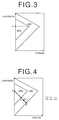
- a point of achromatic color whose lightness is equal to that of the point whose chroma is the highest in the color reproduction range CR o , of the image output system is set as a color compression center P on a lightness-chroma cross-section as shown in Figure 3.
- an intersection A of a straight line passing through the color compression center P and the object picture element P i,j and the boundary of the color reproduction range CR o of the image output system and an intersection B of the straight line passing through the color compression center P and the object picture element P i,j and the boundary of the color read-out range CR I of the image read-out means are determined.
- the chroma signal component C i,j and the enhanced lightness signal component L i,j of the object picture element P i,j are transformed on the basis of the color compression transformation curve thus generated, and color-compressed lightness signal component L3 i,j , hue signal component H i,j and chroma signal component C2 i,j of the object picture element P i,j are output.
- the distance between the color compression center P and the object picture element P i,j is assumed to be d
- the distance d is transformed to d' as shown in Figure 6
- the object picture element P i,j is transformed to P' which is at a distance d' from the compression center P as shown in Figure 7.
- the picture element number signal K i,j approaches (2M+1) ⁇ (2N+1) and c approaches a as the number of picture elements, out of those included in the reference region of (2M+1) ⁇ (2N+1), whose colors are inside the color reproduction range of the color image output means, increases, and the color compression carried out by use of the color compression transformation curve becomes closer to the faithful color reproduction compression processing.
- the picture element number signal K i,j approaches 0 and c approaches b as the number of picture elements, out of those included in the reference region of (2M+1) ⁇ (2N+1), whose colors are outside the color reproduction range of the color image output means, increases, and the color compression carried out by use of the color compression transformation curve becomes closer to the desaturated color reproduction compression processing.
- the color-compressed lightness signal component L3 i,j , hue signal component H i,j and chroma signal component C2 i,j of the object picture element P i,j out put from the color compression circuit 6 are input into the color transformation LUT 7 and the LUT 7 transforms the color-compressed lightness signal component L3 i,j , hue signal component H i,j and chroma signal component C2 i,j of the object picture element P i,j to output Red-signal component R' i,j , Green-signal component G' i,j and Blue-signal component B' i,j on the basis of a lookup table, which has been prepared in advance and relates the values of the color-compressed lightness signal component L3 i,j , hue signal component H i,j and chroma signal component C2 i,j with the values of output Red-signal component R' i,j , Green-signal component G' i,j and Blue-signal component B
- the output Red-signal component R' i,j , Green-signal component G' i,j and Blue-signal component B' i,j output from the color transformation LUT 7 are input into the binary coding circuit 8.
- the binary coding circuit 8 binary-codes the output Red-signal component R' i,j , Green-signal component G' i,j and Blue-signal component B' i,j by pseudo-gradation-processing and outputs two-valued color image signal components Br i,j , Bg i,j and Bb i,j .
- the binary coding circuit 8 may comprise, for instance, a pseudo-gradation-processing circuit which carries out pseudo-gradation-processing based on a halftone dot method.
- the pseudo-gradation-processing may be carried out by other various methods such as a dither method, an error diffusion method and the like.
- the processing described above is carried out for all the picture elements and a color image signal made up of two-valued color image signal components Br i,j , Bg i,j and Bb i,j for all the picture elements is output to the color image output system.
- the color image output system reproduces an image on the basis of the color image signal.
- local contrast is enhanced by the local contrast enhancement circuit 3. Accordingly, local contrast of an image can be successfully enhanced without jump in brightness and/or chromaticity differentiation loss even if the image is such as a picture taken against the light where light parts and dark parts are mingled with each other. Further, a transformation curve for compressing the local-contrast-enhanced color image signal within the color reproduction range of the color image output means is generated according to the proportion of picture elements whose colors are inside the color reproduction range of the color image output means to those whose colors are outside the color reproduction range of the color image output means out of the picture elements around each picture element.
- the color image signal can be compressed without local jump in brightness or chromaticity differentiation loss even if colors inside and outside the color reproduction range are locally concentrated in a small region.
- color compression processing may be carried out without local contrast enhancement processing.
Landscapes
- Engineering & Computer Science (AREA)
- Multimedia (AREA)
- Signal Processing (AREA)
- Image Processing (AREA)
- Facsimile Image Signal Circuits (AREA)
- Color Image Communication Systems (AREA)
Applications Claiming Priority (2)
| Application Number | Priority Date | Filing Date | Title |
|---|---|---|---|
| JP6127799 | 1999-03-09 | ||
| JP11061277A JP2000261680A (ja) | 1999-03-09 | 1999-03-09 | 画像処理方法および装置 |
Publications (3)
| Publication Number | Publication Date |
|---|---|
| EP1035731A2 true EP1035731A2 (fr) | 2000-09-13 |
| EP1035731A3 EP1035731A3 (fr) | 2004-01-07 |
| EP1035731B1 EP1035731B1 (fr) | 2006-09-27 |
Family
ID=13166565
Family Applications (1)
| Application Number | Title | Priority Date | Filing Date |
|---|---|---|---|
| EP00104932A Expired - Lifetime EP1035731B1 (fr) | 1999-03-09 | 2000-03-08 | Procédé et système de traitement d'images |
Country Status (4)
| Country | Link |
|---|---|
| US (1) | US6781715B1 (fr) |
| EP (1) | EP1035731B1 (fr) |
| JP (1) | JP2000261680A (fr) |
| DE (1) | DE60030900T2 (fr) |
Cited By (1)
| Publication number | Priority date | Publication date | Assignee | Title |
|---|---|---|---|---|
| WO2009016137A1 (fr) * | 2007-07-27 | 2009-02-05 | Thomson Licensing | Procédé de mappage de couleurs tenant compte de la distribution des couleurs visées |
Families Citing this family (8)
| Publication number | Priority date | Publication date | Assignee | Title |
|---|---|---|---|---|
| JP3732702B2 (ja) * | 2000-01-31 | 2006-01-11 | 株式会社リコー | 画像処理装置 |
| US6937365B2 (en) * | 2001-05-30 | 2005-08-30 | Polaroid Corporation | Rendering images utilizing adaptive error diffusion |
| US7684640B2 (en) | 2005-10-20 | 2010-03-23 | Sharp Laboratories Of America, Inc. | Methods and systems for automatic digital image enhancement with local adjustment |
| US7684639B2 (en) | 2005-10-20 | 2010-03-23 | Sharp Laboratories Of America, Inc. | Methods and systems for automatic digital image enhancement |
| JP4232800B2 (ja) | 2006-08-03 | 2009-03-04 | 日本電気株式会社 | ラインノイズ除去装置、ラインノイズ除去方法、ラインノイズ除去プログラム |
| JP2011062921A (ja) * | 2009-09-17 | 2011-03-31 | Fuji Xerox Co Ltd | 画像形成装置およびプログラム |
| US9525802B2 (en) * | 2013-07-24 | 2016-12-20 | Georgetown University | Enhancing the legibility of images using monochromatic light sources |
| CN111988592B (zh) * | 2019-05-22 | 2023-06-27 | 瑞昱半导体股份有限公司 | 影像色彩还原与增强电路 |
Family Cites Families (10)
| Publication number | Priority date | Publication date | Assignee | Title |
|---|---|---|---|---|
| EP0486311B1 (fr) | 1990-11-15 | 2001-10-10 | Canon Kabushiki Kaisha | Appareil et procédé de traitement d'images en couleurs |
| JPH04287569A (ja) | 1991-03-18 | 1992-10-13 | Canon Inc | カラー画像処理方法及び装置 |
| US5426517A (en) * | 1992-11-30 | 1995-06-20 | Eastman Kodak Company | Automated tone correction apparatus and method using filtered histogram equalization |
| JP3359116B2 (ja) | 1993-09-29 | 2002-12-24 | キヤノン株式会社 | 画像処理方法及び装置 |
| US5347374A (en) | 1993-11-05 | 1994-09-13 | Xerox Corporation | Cascaded image processing using histogram prediction |
| US5828780A (en) * | 1993-12-21 | 1998-10-27 | Ricoh Company, Ltd. | Image processing apparatus with improved color correction |
| US5450217A (en) | 1994-05-23 | 1995-09-12 | Xerox Corporation | Image-dependent color saturation correction in a natural scene pictorial image |
| US5982926A (en) * | 1995-01-17 | 1999-11-09 | At & T Ipm Corp. | Real-time image enhancement techniques |
| US6463173B1 (en) * | 1995-10-30 | 2002-10-08 | Hewlett-Packard Company | System and method for histogram-based image contrast enhancement |
| JPH1023279A (ja) | 1996-06-28 | 1998-01-23 | Fuji Xerox Co Ltd | 画像処理装置 |
-
1999
- 1999-03-09 JP JP11061277A patent/JP2000261680A/ja active Pending
-
2000
- 2000-03-08 US US09/520,807 patent/US6781715B1/en not_active Expired - Lifetime
- 2000-03-08 DE DE60030900T patent/DE60030900T2/de not_active Expired - Fee Related
- 2000-03-08 EP EP00104932A patent/EP1035731B1/fr not_active Expired - Lifetime
Cited By (1)
| Publication number | Priority date | Publication date | Assignee | Title |
|---|---|---|---|---|
| WO2009016137A1 (fr) * | 2007-07-27 | 2009-02-05 | Thomson Licensing | Procédé de mappage de couleurs tenant compte de la distribution des couleurs visées |
Also Published As
| Publication number | Publication date |
|---|---|
| DE60030900D1 (de) | 2006-11-09 |
| US6781715B1 (en) | 2004-08-24 |
| EP1035731B1 (fr) | 2006-09-27 |
| DE60030900T2 (de) | 2007-01-11 |
| EP1035731A3 (fr) | 2004-01-07 |
| JP2000261680A (ja) | 2000-09-22 |
Similar Documents
| Publication | Publication Date | Title |
|---|---|---|
| US5786906A (en) | Method and apparatus for processing image | |
| JP4677753B2 (ja) | 動画像処理装置及び方法 | |
| JP3676402B2 (ja) | 自然シーン画像のカスケード処理方法及び装置 | |
| EP0684729B1 (fr) | Correction de la saturation des couleurs dépendante de l'image pour des images des scènes naturelles | |
| JP3099354B2 (ja) | 画像処理装置及びこの装置を用いたディジタルカラー複写機 | |
| US6342951B1 (en) | Gamut mapping algorithm using inverted gamma function | |
| US7013043B2 (en) | Method of and apparatus for image processing | |
| JPH0355078B2 (fr) | ||
| JP2004200902A (ja) | 画像処理装置、電子カメラ、及び画像処理プログラム | |
| EP1337115A1 (fr) | Processeur d'image et procede de conversion de systeme colorimetrique | |
| US6781715B1 (en) | Image processing method and system | |
| US7944584B2 (en) | Color-converting device | |
| US6747698B2 (en) | Image interpolating device | |
| JP2906974B2 (ja) | カラー画像処理方法および装置 | |
| JPH04165873A (ja) | 画像処理装置 | |
| JP3845457B2 (ja) | カラーイメージ信号の変換方法及び変換装置 | |
| US6931161B2 (en) | Method for making an exposure adjustment on a rendered image | |
| JPH09275496A (ja) | 画像の輪郭強調処理装置および方法 | |
| JP2002314827A (ja) | 画像処理方法、画像処理装置、及びそれを備えた画像形成装置、画像処理プログラム、並びに記録媒体 | |
| KR100477657B1 (ko) | 디지털 화질 개선 방법 | |
| JP2002112051A (ja) | 画像処理方法および装置 | |
| US20060291015A1 (en) | Applying multiple imaging processes to digital images | |
| JP3150963B2 (ja) | 画像処理方法 | |
| JP3432956B2 (ja) | 画像データ処理装置 | |
| JPH09167225A (ja) | 画像処理装置 |
Legal Events
| Date | Code | Title | Description |
|---|---|---|---|
| PUAI | Public reference made under article 153(3) epc to a published international application that has entered the european phase |
Free format text: ORIGINAL CODE: 0009012 |
|
| 17P | Request for examination filed |
Effective date: 20000308 |
|
| AK | Designated contracting states |
Kind code of ref document: A2 Designated state(s): AT BE CH CY DE DK ES FI FR GB GR IE IT LI LU MC NL PT SE |
|
| AX | Request for extension of the european patent |
Free format text: AL;LT;LV;MK;RO;SI |
|
| PUAL | Search report despatched |
Free format text: ORIGINAL CODE: 0009013 |
|
| AK | Designated contracting states |
Kind code of ref document: A3 Designated state(s): AT BE CH CY DE DK ES FI FR GB GR IE IT LI LU MC NL PT SE |
|
| AX | Request for extension of the european patent |
Extension state: AL LT LV MK RO SI |
|
| 17Q | First examination report despatched |
Effective date: 20040629 |
|
| AKX | Designation fees paid |
Designated state(s): DE FR GB |
|
| GRAP | Despatch of communication of intention to grant a patent |
Free format text: ORIGINAL CODE: EPIDOSNIGR1 |
|
| GRAS | Grant fee paid |
Free format text: ORIGINAL CODE: EPIDOSNIGR3 |
|
| GRAA | (expected) grant |
Free format text: ORIGINAL CODE: 0009210 |
|
| AK | Designated contracting states |
Kind code of ref document: B1 Designated state(s): DE FR GB |
|
| REG | Reference to a national code |
Ref country code: GB Ref legal event code: FG4D |
|
| REF | Corresponds to: |
Ref document number: 60030900 Country of ref document: DE Date of ref document: 20061109 Kind code of ref document: P |
|
| ET | Fr: translation filed | ||
| PLBE | No opposition filed within time limit |
Free format text: ORIGINAL CODE: 0009261 |
|
| STAA | Information on the status of an ep patent application or granted ep patent |
Free format text: STATUS: NO OPPOSITION FILED WITHIN TIME LIMIT |
|
| 26N | No opposition filed |
Effective date: 20070628 |
|
| PGFP | Annual fee paid to national office [announced via postgrant information from national office to epo] |
Ref country code: GB Payment date: 20080305 Year of fee payment: 9 |
|
| PGFP | Annual fee paid to national office [announced via postgrant information from national office to epo] |
Ref country code: DE Payment date: 20080306 Year of fee payment: 9 Ref country code: FR Payment date: 20080311 Year of fee payment: 9 |
|
| GBPC | Gb: european patent ceased through non-payment of renewal fee |
Effective date: 20090308 |
|
| REG | Reference to a national code |
Ref country code: FR Ref legal event code: ST Effective date: 20091130 |
|
| PG25 | Lapsed in a contracting state [announced via postgrant information from national office to epo] |
Ref country code: DE Free format text: LAPSE BECAUSE OF NON-PAYMENT OF DUE FEES Effective date: 20091001 |
|
| PG25 | Lapsed in a contracting state [announced via postgrant information from national office to epo] |
Ref country code: FR Free format text: LAPSE BECAUSE OF NON-PAYMENT OF DUE FEES Effective date: 20091123 Ref country code: GB Free format text: LAPSE BECAUSE OF NON-PAYMENT OF DUE FEES Effective date: 20090308 |