EP1035733A2 - Méthode et dispositif de combinaison d'images vidéo - Google Patents
Méthode et dispositif de combinaison d'images vidéo Download PDFInfo
- Publication number
- EP1035733A2 EP1035733A2 EP00104761A EP00104761A EP1035733A2 EP 1035733 A2 EP1035733 A2 EP 1035733A2 EP 00104761 A EP00104761 A EP 00104761A EP 00104761 A EP00104761 A EP 00104761A EP 1035733 A2 EP1035733 A2 EP 1035733A2
- Authority
- EP
- European Patent Office
- Prior art keywords
- picture
- frame
- macro blocks
- signal
- pictures
- Prior art date
- Legal status (The legal status is an assumption and is not a legal conclusion. Google has not performed a legal analysis and makes no representation as to the accuracy of the status listed.)
- Withdrawn
Links
- 238000000034 method Methods 0.000 title claims description 23
- 230000005540 biological transmission Effects 0.000 claims description 3
- 230000001427 coherent effect Effects 0.000 claims 2
- 230000000717 retained effect Effects 0.000 abstract 1
- 238000010586 diagram Methods 0.000 description 9
- 239000000284 extract Substances 0.000 description 3
- 230000000694 effects Effects 0.000 description 2
- 230000002123 temporal effect Effects 0.000 description 2
- 230000006835 compression Effects 0.000 description 1
- 238000007906 compression Methods 0.000 description 1
- 230000001419 dependent effect Effects 0.000 description 1
- 238000000605 extraction Methods 0.000 description 1
- 230000002441 reversible effect Effects 0.000 description 1
- 230000001360 synchronised effect Effects 0.000 description 1
Images

Classifications
-
- H—ELECTRICITY
- H04—ELECTRIC COMMUNICATION TECHNIQUE
- H04N—PICTORIAL COMMUNICATION, e.g. TELEVISION
- H04N5/00—Details of television systems
- H04N5/44—Receiver circuitry for the reception of television signals according to analogue transmission standards
- H04N5/445—Receiver circuitry for the reception of television signals according to analogue transmission standards for displaying additional information
- H04N5/45—Picture in picture, e.g. displaying simultaneously another television channel in a region of the screen
-
- H—ELECTRICITY
- H04—ELECTRIC COMMUNICATION TECHNIQUE
- H04N—PICTORIAL COMMUNICATION, e.g. TELEVISION
- H04N21/00—Selective content distribution, e.g. interactive television or video on demand [VOD]
- H04N21/40—Client devices specifically adapted for the reception of or interaction with content, e.g. set-top-box [STB]; Operations thereof
- H04N21/43—Processing of content or additional data, e.g. demultiplexing additional data from a digital video stream; Elementary client operations, e.g. monitoring of home network or synchronising decoder's clock; Client middleware
- H04N21/431—Generation of visual interfaces for content selection or interaction; Content or additional data rendering
- H04N21/4312—Generation of visual interfaces for content selection or interaction; Content or additional data rendering involving specific graphical features, e.g. screen layout, special fonts or colors, blinking icons, highlights or animations
- H04N21/4316—Generation of visual interfaces for content selection or interaction; Content or additional data rendering involving specific graphical features, e.g. screen layout, special fonts or colors, blinking icons, highlights or animations for displaying supplemental content in a region of the screen, e.g. an advertisement in a separate window
-
- H—ELECTRICITY
- H04—ELECTRIC COMMUNICATION TECHNIQUE
- H04N—PICTORIAL COMMUNICATION, e.g. TELEVISION
- H04N21/00—Selective content distribution, e.g. interactive television or video on demand [VOD]
- H04N21/40—Client devices specifically adapted for the reception of or interaction with content, e.g. set-top-box [STB]; Operations thereof
- H04N21/41—Structure of client; Structure of client peripherals
- H04N21/426—Internal components of the client ; Characteristics thereof
Definitions
- the invention relates to a method for adding a moving picture on top of a larger moving picture.
- the method is applicable to cases in which the picture signals are compressed digital signals.
- the invention also relates to an arrangement for adding a moving picture on top of a larger moving picture.
- the picture-in-picture (PIP) feature is a widely used technique at the transmitting end when making a television program, for example.
- a considerably smaller picture is temporarily inset which displays, say, a simultaneous event that is likely to interest the viewer.
- the addition of a secondary picture to the main picture may also occur at the receiving end, controlled by the user of the receiver.
- One or more smaller pictures may e.g. display programs running on other channels while the main picture is being viewed without interruption.
- the present invention relates particularly to the use of the PIP feature at the receiving end.
- a digitized video signal When compressing a digitized video signal it is customary to divide an individual picture frame into blocks which typically comprise 8x8 picture elements, or pixels. A square portion of a frame, comprised of four blocks, is called a macro block. Compression, i.e. reduction of the number of bits, is realized using intra-frame coding and inter-frame coding.
- the former includes e.g. predictive coding utilizing positional redundancy or the use of discrete cosine transform (DCT) concentrating signal energy of a picture block.
- DCT discrete cosine transform
- the numbers produced by the transform are quantized in a manner that reduces the quantity of bits and ordered in a sequence where the occurrence of strings of consecutive zeroes is statistically high.
- Inter-frame coding includes predictive inter-frame coding, motion estimation comparing the contents of macro blocks at different positions, utilizing temporal redundancy and temporal interpolation of reference frames in order to produce the code for the frames between them. By combining various coding methods it is possible to reduce the number of bits transmitted down to a hundredth part of the original without substantially compromising the quality of the picture.
- a video decoder performs the reverse operations. On the transmission path, several video signals may travel packet switched in the same transport stream (TS) so that the receiver first has to extract an individual video signal from it.
- TS transport stream
- the system comprises decoders 110 and 120 as well as a PIP unit 130.
- a video signal ES1 (so-called “elementary stream") is brought to decoder 110 and video signal ES2 to decoder 120.
- Signals ES1 and ES2 are encoded e.g. according to the MPEG2 (Motion Picture Experts Group) standard.
- Decoder 110 outputs video signal VD1 and decoder 120 video signal VD2.
- the PIP unit 130 comprises a scaling unit 131, selector 132 and timing unit 133.
- Signal VD1 is directed straight to the selector.
- Signal VD2 is directed to the scaling unit 131 the output signal VD2' of which is conducted to the selector.
- the output signal VDO of the selector 132 is either signal VD1 or signal VD2' depending on the status of the selection signal S output by the timing unit 133.
- signal S goes into a state that conducts signal VD2' to the output of selector 132.
- signal S in a state that conducts signal VD1 to the output of selector 132.
- the functional blocks shown in Fig. 1 are realized partly in software and partly in hardware.
- a disadvantage of the method described above is that it requires a double decoding operation. So, when using a signal processor, a double decoding capacity is required of it, which results in considerable extra costs. Another disadvantage is that in practice, for the reason stated above, only one mini-picture may be inset in the main picture.
- An object of the invention is to eliminate the above-described disadvantages associated with the prior art.
- the picture-in-picture operation according to the invention is characterized by what is expressed in the independent claims. Preferred embodiments of the invention are presented in the dependent claims.
- the main idea of the invention is that the video signals are combined prior to the decoding.
- the encoded macro blocks of the area of the main picture intended for the mini-picture are replaced by macro blocks from another picture. These are obtained e.g. by taking macro blocks at regular intervals in such a manner that their total number equals the number of macro blocks that corresponds to the mini-picture area.
- a single mini-picture macro block may also be produced by assembling it from selected blocks of several original macro blocks or by interpolating a plurality of original macro blocks into a single macro block. The combined signal is then decoded.
- An advantage of the invention is that a receiver only needs one decoder. In video processing, decoding is the part that requires the most computing. Another advantage of the invention is that several mini-pictures can be inset in the main picture with only a minimum added computing. A further advantage of the invention is that the decoder is detached from the rest of the receiver so that the capacity of the transmission system between the decoder and receiver may be dimensioned according to the band of one channel only. Yet another advantage of the invention is that if the video signals to be combined are brought to the receiver in the same transport stream, it is only required one complete demultiplexer which extracts from the transport stream the packets relating to all auxiliary activities as well.
- Fig. 1 was already discussed in conjunction with the description of the prior art.
- Fig. 2 shows in the form of functional block diagram a PIP implementation according to the invention. It comprises a PIP unit 230 and decoder 210.
- the PIP unit comprises a scaling unit 231, selector 232 and timing unit 233.
- Video signals ES1 and ES2 comprised of codes of horizontally adjacent macro blocks of a picture are brought to the system.
- Signal ES1 is conducted direct to the selector 232.
- Signal ES2 is conducted to the scaling unit 231 in which the picture is reduced using a known method.
- the output signal ES2' of the scaling unit is conducted to the selector 232.
- the output signal CS of the selector is either signal ES1 or signal ES2', depending on the status of the selection signal S output by the timing unit 233.
- signal S is in state that directs signal ES2' to the output of selector 232. At other times signal S is in state that directs signal ES1 to the output of selector 232.
- Signal S is generated for the video signals ES1 and ES2 from temporally bound synchronization signals SYN, which are used to synchronize the operation of other units, too.
- Signal CS is conducted to decoder 210 which outputs a complete digital video signal VDO. Compared to the structure of Fig. 1 this structure has one decoder less, which means an almost fifty percent drop in the need for computing capacity since decoding requires much more computation than the PIP function.
- Fig. 3 shows an example of an image produced by signal VDO of Fig. 1 or 2. It has a main picture 31 and an inset mini-picture PIP.
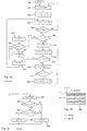
- Fig. 4a shows in the form of flow diagram an example of the operation of the scaling unit 231.
- a complete frame comprises C macro blocks, or macros, horizontally and R macros vertically.
- every I th macro is selected both horizontally and vertically in the frame of the picture to be reduced, the selected macros constituting signal ES2' of Fig. 2.
- program reception is started.
- the processing of an individual frame is started.
- the values of variables r, i, c and j needed in the processing are initialized.
- Variable r is the number of a macro row in the complete picture
- variable c is the number of a macro column in the complete frame.
- Variable i is a row number, counting from the row that was last used to select macros for a mini-picture.
- Variable j is a column number, counting from the colunm that was last used to select a macro for a mini-picture.
- row numbers r and i are incremented.
- step 405 it is checked whether the last row of the frame was already processed. If so, the processing of the next frame is begun (step 402). If the frame is unfinished, it is checked according to step 406 whether the row being processed is a row on which macros are to be selected. If not, the column number c is incremented, step 407. In step 408 it is checked whether the macro row has come to an end.
- step 409 If not, the process moves on to the next macro on the row, step 409, and repeats steps 407 and 408. If the macro row has come to an end, the column number c is reset in step 410 and the process continues at step 404. If the row is a row on which macros are to be selected, the row number i is reset (step 411) and column numbers c and j are incremented (step 412). In step 413 it is checked whether the macro row has come to an end. If not, the process moves on to the next macro, step 414. In step 415 it is checked whether the column processed is a column on which macros are to be selected. If not, the process continues at step 412. If it is, the macro is saved according to step 416. At the same time column number j is reset. The process then continues at step 412.
- Fig. 4b shows the area of a mini-picture. It comprises vertically R' macro block areas and horizontally C' macro block areas. Corresponding to the markings of Fig. 4a, the number of rows R' equals the ratio R/I rounded off to the nearest smaller integer, and the number of columns C' equals the ratio C/I rounded off to the nearest smaller integer.
- the mini-picture stalls vertically from row r1 of the complete frame and horizontally from column c1 of the complete frame.
- Fig. 4c shows in the form of flow diagram an example of the operation of the timing unit 233.
- a logic element or program corresponding to the diagram has at its disposal the values of variables r and c produced by the operation according to Fig. 4a.
- step 421 the value of the row variable r and the value of the column variable c are read.
- step 422 it is checked whether the current position in the complete frame is on a row that belongs to the mini-picture area. If not, selection signal S is set to zero (step 424), which state corresponds in Fig. 2 to the selection of signal ES1 by selector 232.
- step 423 If the current row falls within the mini-picture area, it is checked according to step 423 whether the current position in the complete frame is in a column that belongs to the mini-picture area. If not, the process moves on to step 424. If the current column falls within the mini-picture area, selection signal S is set to one (step 425), which state corresponds in Fig. 2 to the selection of signal ES2' by selector 232.
- the selling of signal S is realized in a synchronized manner between two consecutive macro block times. After the selling, the values of variables r and c are read again. Operation corresponding to Fig. 4c may also be realized such that the comparison corresponding to step 422 is made after the value of variable r has been incremented, and the comparison corresponding to step 423 is made after the value of variable c has been incremented.
- the position of the mini-picture to be inset in the main picture is determined by means of parameters r1, c1.
- the size of the mini-picture is determined by parameter I.
- the width-to-height ratio of the mini-picture is thus the same as that of the main picture. The ratio can be made freely selectable if an additional parameter is introduced in the program, determining how many columns or rows of the mini-picture frame produced as described above are included in the final mini-picture.
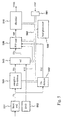
- Fig. 5 shows an example of a system in which pictures are combined in accordance with the invention.
- the system comprises a front end 551 which receives a radio-frequency signal and outputs a baseband digital transport stream signal TS.
- Signal TS comprises consecutive packets comprised of a header and transport data proper.
- the header comprises, among other things, the packet identity data (PID).
- PID packet identity data
- the transport stream may include packets containing the code of several different video signals and, in addition, packets associated with various auxiliary activities of the receiver.
- Signal TS is conducted to a TS multiplexer 541. This is a complete demultiplexer, which means it monitors a relatively large amount of PID numbers and extracts from the transport stream the respective packets.
- the demultiplexer 541 sends the code ES1 of the selected video signal to a selector 545 and the data contents of the other extracted packets to a host processor 560 in the system.
- Signal TS is also conducted to a second TS demultiplexer 542.
- This is a relatively simple demultiplexer which extracts from the transport stream only the packets associated with a particular video signal.
- the demultiplexer 542 produces video signal ES2 and feeds it to a PIP unit 530, to a scaling unit in it.
- video signal ES3 from a video disc drive 552 is also brought to selector 545.
- Signal ES3 is encoded in the same manner as signals ES1 and ES2.
- Selector 545 outputs the main picture signal ESs, which is either ES1 or ES3, depending on a control issued by the host processor 560.
- Signal ESs is conducted to the PIP unit 530, which corresponds to the PIP unit 230 in Fig. 2.
- Signal ES3 is also conducted direct to the PIP unit 530, to a scaling unit in it.
- Unit 530 reduces the number of macro blocks of signal ES2, signal ES3 or both, depending on a control issued by the processor 560.
- unit 530 substitutes macro blocks of the scaled-down pictures for a certain portion of the macro blocks of signal ESs corresponding to the main picture. Thus in this example it is possible to inset one or two pictures in the main picture.
- the output signal MP of unit 530 is conducted to a common decoder 510 which outputs a complete digital video signal VDO. It is used to generate the analog or digital signals controlling the display.
- the system also comprises a unit 561 to receive selection and control data from the user.
- the host processor 560 is connected with the other units via a bus 562.
Landscapes
- Engineering & Computer Science (AREA)
- Multimedia (AREA)
- Signal Processing (AREA)
- Business, Economics & Management (AREA)
- Marketing (AREA)
- Compression Or Coding Systems Of Tv Signals (AREA)
- Two-Way Televisions, Distribution Of Moving Picture Or The Like (AREA)
Applications Claiming Priority (2)
| Application Number | Priority Date | Filing Date | Title |
|---|---|---|---|
| FI990537 | 1999-03-11 | ||
| FI990537A FI106421B (fi) | 1999-03-11 | 1999-03-11 | Menetelmä ja järjestely videokuvien yhdistämiseksi |
Publications (2)
| Publication Number | Publication Date |
|---|---|
| EP1035733A2 true EP1035733A2 (fr) | 2000-09-13 |
| EP1035733A3 EP1035733A3 (fr) | 2003-08-06 |
Family
ID=8554166
Family Applications (1)
| Application Number | Title | Priority Date | Filing Date |
|---|---|---|---|
| EP00104761A Withdrawn EP1035733A3 (fr) | 1999-03-11 | 2000-03-04 | Méthode et dispositif de combinaison d'images vidéo |
Country Status (3)
| Country | Link |
|---|---|
| US (1) | US6724434B1 (fr) |
| EP (1) | EP1035733A3 (fr) |
| FI (1) | FI106421B (fr) |
Cited By (3)
| Publication number | Priority date | Publication date | Assignee | Title |
|---|---|---|---|---|
| WO2004056100A1 (fr) * | 2002-12-13 | 2004-07-01 | Koninklijke Philips Electronics N.V. | Unite d'affichage de television |
| EP2031879A1 (fr) * | 2007-08-29 | 2009-03-04 | Barco NV | Multiafficheur basé sur la fusion de flux de sortie de codecs spatio-adaptatifs dans un domaine compressé |
| US9462295B2 (en) | 2002-10-21 | 2016-10-04 | Entropic Communications, Llc | Manipulating sub-pictures of a compressed video signal |
Families Citing this family (15)
| Publication number | Priority date | Publication date | Assignee | Title |
|---|---|---|---|---|
| JP3721867B2 (ja) * | 1999-07-07 | 2005-11-30 | 日本電気株式会社 | 映像表示装置及び表示方法 |
| KR20030036160A (ko) * | 2000-05-22 | 2003-05-09 | 가부시키가이샤 소니 컴퓨터 엔터테인먼트 | 정보 처리 장치, 그래픽 처리 유닛, 그래픽 처리 방법,저장 매체 및 컴퓨터 프로그램 |
| KR20020040870A (ko) * | 2000-08-16 | 2002-05-30 | 요트.게.아. 롤페즈 | 다중 윈도우 비디오 신호 발생기 |
| US7023492B2 (en) * | 2000-10-19 | 2006-04-04 | Microsoft Corporation | Method and apparatus for encoding video content |
| US7206029B2 (en) * | 2000-12-15 | 2007-04-17 | Koninklijke Philips Electronics N.V. | Picture-in-picture repositioning and/or resizing based on video content analysis |
| KR100399999B1 (ko) * | 2001-02-05 | 2003-09-29 | 삼성전자주식회사 | 멀티스트림이 기록된 기록매체, 그 기록장치, 그기록방법, 그 재생장치, 및 그 재생방법 |
| WO2005041192A1 (fr) * | 2003-10-24 | 2005-05-06 | Koninklijke Philips Electronics N.V. | Procede et appareil destines a fournir un signal video |
| WO2006041832A2 (fr) * | 2004-10-05 | 2006-04-20 | Vectormax Corporation | Procede et systeme permettant de diffuser des donnees multimedia |
| US20060256122A1 (en) * | 2005-05-13 | 2006-11-16 | Rai Barinder S | Method and apparatus for streaming data from multiple devices over a single data bus |
| JP2007079809A (ja) * | 2005-09-13 | 2007-03-29 | Fuji Xerox Co Ltd | 電子ペーパシステム |
| US8515194B2 (en) | 2007-02-21 | 2013-08-20 | Microsoft Corporation | Signaling and uses of windowing information for images |
| US20090019068A1 (en) * | 2007-07-09 | 2009-01-15 | Legend Silicon Corp. | Decoder with reduced memory requirements decoding of video signals |
| US20090016428A1 (en) * | 2007-07-09 | 2009-01-15 | Legend Silicon Corp. | Method and apparatus for decoding of video signals having reduced memory and a novel method for output therefore |
| JP4377948B1 (ja) * | 2008-06-30 | 2009-12-02 | 株式会社東芝 | 映像信号処理装置及び映像信号処理方法 |
| JP2014192566A (ja) * | 2013-03-26 | 2014-10-06 | Sony Corp | 映像処理装置、映像処理方法およびコンピュータプログラム |
Citations (1)
| Publication number | Priority date | Publication date | Assignee | Title |
|---|---|---|---|---|
| US4924522A (en) * | 1987-08-26 | 1990-05-08 | Ncr Corporation | Method and apparatus for displaying a high resolution image on a low resolution CRT |
Family Cites Families (15)
| Publication number | Priority date | Publication date | Assignee | Title |
|---|---|---|---|---|
| JPH0622215A (ja) * | 1992-07-06 | 1994-01-28 | Toshiba Corp | 映像送信方法、該方法に用いる映像送信装置および映像受信装置 |
| JP3149303B2 (ja) * | 1993-12-29 | 2001-03-26 | 松下電器産業株式会社 | デジタル画像符号化方法及びデジタル画像復号化方法 |
| CN1085005C (zh) * | 1994-04-15 | 2002-05-15 | 皇家菲利浦电子有限公司 | 用于发送和接收视频信号的装置和方法 |
| KR0144260B1 (ko) | 1994-11-15 | 1998-07-15 | 구자홍 | 피아이피 기능의 에이치디티브이 |
| US5623308A (en) * | 1995-07-07 | 1997-04-22 | Lucent Technologies Inc. | Multiple resolution, multi-stream video system using a single standard coder |
| KR100197837B1 (ko) | 1995-09-14 | 1999-06-15 | 윤종용 | 더블스크린을 이용한 정보 및 외부신호 표시장치 |
| CA2191632A1 (fr) | 1996-02-13 | 1997-08-14 | James Lee Combs | Processeur video pour traiter deux signaux video composites analogiques |
| US6356313B1 (en) * | 1997-06-26 | 2002-03-12 | Sony Corporation | System and method for overlay of a motion video signal on an analog video signal |
| US5847771A (en) * | 1996-08-14 | 1998-12-08 | Bell Atlantic Network Services, Inc. | Digital entertainment terminal providing multiple digital pictures |
| CA2243700C (fr) * | 1996-11-21 | 2005-04-19 | Philips Electronics N.V. | Emission et reception de programmes de television et service auxiliaire de transmission de donnees |
| US5995146A (en) * | 1997-01-24 | 1999-11-30 | Pathway, Inc. | Multiple video screen display system |
| US6057884A (en) * | 1997-06-05 | 2000-05-02 | General Instrument Corporation | Temporal and spatial scaleable coding for video object planes |
| US6313822B1 (en) * | 1998-03-27 | 2001-11-06 | Sony Corporation | Method and apparatus for modifying screen resolution based on available memory |
| US6167084A (en) * | 1998-08-27 | 2000-12-26 | Motorola, Inc. | Dynamic bit allocation for statistical multiplexing of compressed and uncompressed digital video signals |
| US6445828B1 (en) * | 1998-09-28 | 2002-09-03 | Thomson Licensing S.A. | Transform domain resizing of an image compressed with field encoded blocks |
-
1999
- 1999-03-11 FI FI990537A patent/FI106421B/fi active
-
2000
- 2000-03-04 EP EP00104761A patent/EP1035733A3/fr not_active Withdrawn
- 2000-03-09 US US09/521,836 patent/US6724434B1/en not_active Expired - Lifetime
Patent Citations (1)
| Publication number | Priority date | Publication date | Assignee | Title |
|---|---|---|---|---|
| US4924522A (en) * | 1987-08-26 | 1990-05-08 | Ncr Corporation | Method and apparatus for displaying a high resolution image on a low resolution CRT |
Non-Patent Citations (2)
| Title |
|---|
| LE GALL ET AL: "The MPEG video compression algorithm", SIGNAL PROCESSING. IMAGE COMMUNICATION, ELSEVIER SCIENCE PUBLISHERS, AMSTERDAM, NL, vol. 4, no. 2, 1 April 1992 (1992-04-01), pages 129 - 140, XP026672562, ISSN: 0923-5965, [retrieved on 19920401], DOI: 10.1016/0923-5965(92)90019-C * |
| MING LIOU: "Overview of the px64 kbit/s video coding standard", COMMUNICATIONS OF THE ACM, ASSOCIATION FOR COMPUTING MACHINERY, INC, UNITED STATES, vol. 34, no. 4, 1 April 1991 (1991-04-01), pages 59 - 63, XP058105889, ISSN: 0001-0782, DOI: 10.1145/103085.103091 * |
Cited By (4)
| Publication number | Priority date | Publication date | Assignee | Title |
|---|---|---|---|---|
| US9462295B2 (en) | 2002-10-21 | 2016-10-04 | Entropic Communications, Llc | Manipulating sub-pictures of a compressed video signal |
| US9699477B2 (en) | 2002-10-21 | 2017-07-04 | Entropic Communications, Llc | Manipulating sub-pictures of a compressed video signal |
| WO2004056100A1 (fr) * | 2002-12-13 | 2004-07-01 | Koninklijke Philips Electronics N.V. | Unite d'affichage de television |
| EP2031879A1 (fr) * | 2007-08-29 | 2009-03-04 | Barco NV | Multiafficheur basé sur la fusion de flux de sortie de codecs spatio-adaptatifs dans un domaine compressé |
Also Published As
| Publication number | Publication date |
|---|---|
| FI106421B (fi) | 2001-01-31 |
| EP1035733A3 (fr) | 2003-08-06 |
| FI990537L (fi) | 2000-09-12 |
| US6724434B1 (en) | 2004-04-20 |
| FI990537A0 (fi) | 1999-03-11 |
Similar Documents
| Publication | Publication Date | Title |
|---|---|---|
| EP1035733A2 (fr) | Méthode et dispositif de combinaison d'images vidéo | |
| CN1087124C (zh) | 具有模拟和数字两种视频方式的接收机及其接收方法 | |
| US6091458A (en) | Receiver having analog and digital video modes and receiving method thereof | |
| US6262770B1 (en) | Methods and apparatus for decoding high and standard definition images and for decoding digital data representing images at less than the image's full resolution | |
| JP3737586B2 (ja) | ディジタルビデオデータストリームの前処理装置 | |
| US6357045B1 (en) | Apparatus and method for generating a time-multiplexed channel surfing signal at television head-end sites | |
| US20020039385A1 (en) | Apparatus and method for decoding moving picture capable of performing simple and easy multiwindow display | |
| EP1725043A2 (fr) | Sélection et accès à des sous-images MPEG sans codage additionnel | |
| JP2001285876A (ja) | 画像符号化装置とその方法、ビデオカメラ、画像記録装置、画像伝送装置 | |
| JPH10234043A (ja) | 動画像符号化/復号化装置 | |
| KR101344171B1 (ko) | 데이터 압축 방법 및 시스템, 및 컴퓨터 판독가능한 기록 매체 | |
| JPH11122610A (ja) | 画像符号化方法及び画像復号化方法並びにこれらの装置 | |
| JPH08149466A (ja) | 動画像処理方法及び処理装置 | |
| US5973744A (en) | Apparatus for decoding video data | |
| CN102905126A (zh) | 图像处理方法、编码设备、解码设备以及图像处理装置 | |
| JP4185086B2 (ja) | 画像処理装置 | |
| JP3589913B2 (ja) | デジタル信号受信装置、デジタル信号処理装置およびプログラム記録媒体 | |
| KR980013375A (ko) | 아날로그와 디지털 비디오 모드를 갖는 수신기와 그 수신방법(Receiver having analog and digital video moed and receiving method thereof) | |
| JP3880580B2 (ja) | デジタル信号受信装置、デジタル信号処理装置およびプログラム記録媒体 | |
| JPS63234787A (ja) | 高能率符号化された画像信号の復号装置 | |
| JPS6146684A (ja) | フレ−ム間符号化・復号化方式および装置 | |
| JP2003219420A (ja) | 画像再生装置 | |
| JP2004056234A (ja) | 画像符号化装置および画像符号化方法 | |
| JPH10341433A (ja) | 画像符号化装置及び画像復号化装置 | |
| JP2006020353A (ja) | 画像信号符号化装置および方法、画像信号復号装置および方法 |
Legal Events
| Date | Code | Title | Description |
|---|---|---|---|
| PUAI | Public reference made under article 153(3) epc to a published international application that has entered the european phase |
Free format text: ORIGINAL CODE: 0009012 |
|
| AK | Designated contracting states |
Kind code of ref document: A2 Designated state(s): AT BE CH CY DE DK ES FI FR GB GR IE IT LI LU MC NL PT SE |
|
| AX | Request for extension of the european patent |
Free format text: AL;LT;LV;MK;RO;SI |
|
| RAP1 | Party data changed (applicant data changed or rights of an application transferred) |
Owner name: NOKIA CORPORATION |
|
| PUAL | Search report despatched |
Free format text: ORIGINAL CODE: 0009013 |
|
| AK | Designated contracting states |
Designated state(s): AT BE CH CY DE DK ES FI FR GB GR IE IT LI LU MC NL PT SE |
|
| AX | Request for extension of the european patent |
Extension state: AL LT LV MK RO SI |
|
| 17P | Request for examination filed |
Effective date: 20031204 |
|
| AKX | Designation fees paid |
Designated state(s): DE FR GB IT |
|
| 17Q | First examination report despatched |
Effective date: 20041202 |
|
| RAP1 | Party data changed (applicant data changed or rights of an application transferred) |
Owner name: NOKIA CORPORATION |
|
| RAP1 | Party data changed (applicant data changed or rights of an application transferred) |
Owner name: NOKIA TECHNOLOGIES OY |
|
| STAA | Information on the status of an ep patent application or granted ep patent |
Free format text: STATUS: THE APPLICATION IS DEEMED TO BE WITHDRAWN |
|
| 18D | Application deemed to be withdrawn |
Effective date: 20181002 |