EP1035802B1 - System zur rekonstruktion der torquiertheit zwischen dem natürlichen knie und dem bereich der natürlichen hüfte - Google Patents
System zur rekonstruktion der torquiertheit zwischen dem natürlichen knie und dem bereich der natürlichen hüfte Download PDFInfo
- Publication number
- EP1035802B1 EP1035802B1 EP98950033A EP98950033A EP1035802B1 EP 1035802 B1 EP1035802 B1 EP 1035802B1 EP 98950033 A EP98950033 A EP 98950033A EP 98950033 A EP98950033 A EP 98950033A EP 1035802 B1 EP1035802 B1 EP 1035802B1
- Authority
- EP
- European Patent Office
- Prior art keywords
- femur
- nail
- natural
- jig
- knee joint
- Prior art date
- Legal status (The legal status is an assumption and is not a legal conclusion. Google has not performed a legal analysis and makes no representation as to the accuracy of the status listed.)
- Expired - Lifetime
Links
Images




Classifications
-
- A—HUMAN NECESSITIES
- A61—MEDICAL OR VETERINARY SCIENCE; HYGIENE
- A61B—DIAGNOSIS; SURGERY; IDENTIFICATION
- A61B17/00—Surgical instruments, devices or methods
- A61B17/14—Surgical saws
- A61B17/15—Guides therefor
- A61B17/154—Guides therefor for preparing bone for knee prosthesis
- A61B17/155—Cutting femur
Definitions
- the present invention relates to a system for the reconstruction of the natural torqueness between the natural knee and the area of the natural hip in an arrangement between an artificial knee joint and the area of the natural hip after partial resection of the natural condyles of the knee joint and placement of a femoral part of the artificial knee of certain size on the resection surfaces of the Femur bone.
- Torqueness is understood to mean turning the femur insichyer, that to a person-specific angle between the knee joint on the one hand and the femoral neck and femoral head on the other hand, what does that Running behavior and the running pattern significantly influenced.
- the replacement of the natural knee joint for example, is now proving as a result of a tumor, through an artificial total replacement implant as necessary, the natural joint parts must be partially resected and by Implant components to be replaced.
- the femoral resection in conventionally carried out, it may be the case that the Femur component of the artificial knee at a different angle to the hip area stands as the natural knee joint before resection, i.e. So that the natural torqueness no longer changes after the operation Finds the entire system of the femur again.
- a changed running behavior and a the patient's changed movement pattern is the immediate consequence.
- a device for defining resection surfaces on the femur and on the Tibia for the preparation of an implantation of a total knee joint endoprosthesis is known from DE-C-44 23 717.
- the Emphasis is placed on the ventral and dorsal incision on the femur is made exactly parallel to the frontal resection surface on the Tibia.
- This document gives with regard to a possible twist angle no indication in the preparation of the resection surfaces, so that it is improper handling of the device disclosed in this document in addition to that the torqueness after the operation before that is completely different. However, this cannot be done easily correct, especially since at least one more serious intervention would be required.
- the system will have a nail gauge with an exact cuboid-shaped system block, which on its seen from the ventral End face has a leg protruding therefrom and pointing towards the femur, which at its end has a femoral contact probe in the form of a vertical one the leg of the standing bolt to the ventrally located punctiform support holds on the femur, and on its end face as seen dorsally at least one stop tab protruding therefrom and pointing towards the femur point-like contact on both dorsal points Has condyle rollers, the contact block through pairs of holes is interspersed, their arrangement the respective size of the femoral part represents through which fixation nails can be set, which the The position of the contact block on the femur, and the Attachment block can be removed from it, leaving the fixation nails behind is, as well as a saw template with the same basic shape as the system block of the Nail gauge with identical arrangement of the pairs of holes in the contact block, which can
- the connecting element between the nail gauge and the saw gauge are accordingly the fixation nails, which are in pairs of holes both in the contact block and also fit in the saw gauge - depending on the size of the joint - so that the position the nail gauge is transferred to the position of the saw gauge on the Femoral stump.
- the prerequisite for using the system is first Production of a horizontal contact surface for the femoral part of the artificial Knee joint. Here the sliding parts of the natural condyles away. The dorsal condyle rollers remain in approx. 90% of the operations undamaged and can thus serve as a point of reference for the determination of the Torqueness can be used.
- the system Starting point of the consideration at the The system is that only a stable three-point position is able, a stable one To develop a system for mapping torqueness. Two of the three points are determined by the dorsal contact points of the mentioned Stop tab on the two condylar rollers.
- the still missing third point for the three-point support of the nail gauge is determined by the femoral contact probe on the opposite Side, i.e. ventrally located, for a point contact point with the Femur cares.
- the surgeon must first - after the size of the implant Part of the femur has been clearly defined - the horizontal contact surface on Create the femur and then place the nail gauge on the femur stump so that a stable three-point support of the nail gauge on the femur stump comes from the femoral contact probe and the at least one Stop tab for the two condylar rollers.
- the dorsal section, the ventral section and the two diagonal cuts acts in detail the dorsal section, the ventral section and the two diagonal cuts, such that the so produced Diagonal cut surfaces connect the horizontal contact surface with the dorsal or ventral resection surface. Then the femoral part of the artificial The knee joint is fixed to the femur with the corresponding contact surfaces, be it cementless or using bone cement.
- a typical femur part for an artificial knee joint with appropriate Contact surfaces are shown, for example, in DE-A-41 41 757.
- the lateral condyle of the femur is higher than the medial Condyle.
- the imaginary connecting line from lateral to medial between the two condyles are therefore inclined to the horizontal.
- Fig. 1 shows the frontal view of the nail gauge 30 as the condyles 44th of the natural knee joint overlaps at the distal end of the femur 10.
- the Nail gauge 30 consists essentially of an exactly cuboid System block 31.
- On the dorsal side (in Fig. 1 below) is one Stirring tab 32 stirred, which the rear condyle rollers 39, 39 ' only touched at points A and B.
- the stop tab is present 32 connected to the system block via a threaded spindle 35, which with a knurled screw 43 works together as a gear mechanism so that the distance of the stop plate 32 from the contact block 31 can be varied can, such that the nail gauge 30 in the manner of a slide gauge for Sizing and fixing of the femoral part of the artificial Knee joint serves.
- Points A and B form two points for the targeted one stable three-point system.
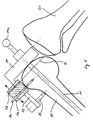
- the third point C (Fig. 4) is the point of contact of the femoral contact probe 36 of the nail gauge 30.
- the femoral contact probe 36 is formed as a perpendicular to one of the ventral end face of the contact block 31 projecting leg 37 pointing to the femur standing bolt.
- the contact block 31 is interspersed with a number of pairs of holes 33, 34, each pair corresponds to a certain size of a femoral part.
- fixation nails 38 are designed so that the Nail gauge 30 without further ado, leaving the fixation nails 38 in Femur 10 can be deducted from this.
- the fixation nails 38 point so no thickened head.
- the saw jig 40 (FIG. 2) is used.
- the saw jig 40 has the same hole pair hole pattern as the nail gauge 30.
- the Saw jig 40 can now be placed on those remaining in the femur Fixation nails 38 are set. Because the sizing is in advance has been made, the slots 41 are for the production of vertical cuts ventrally and dorsally as well as the slots 42 for the Diagonal cuts automatically in the correct position to the femur, the Torqueness is maintained due to the application of the system. By The ventral cut V, the Dorsal section D and the two diagonal sections Di are made.
- the saw gauge 40 has two additional ones Fixation screws 45 (Fig. 3) locked on the femur, so that due to the Sawing process no displacement of the saw jig 40 can take place.
- the horizontal contact surface H (Fig. 5) manufactured.
- a contact block 17 is placed frontally on the femur 10 set.
- a guide rod 11 with dumbbell passing through the contact block 17 11a reaches into the medullary space of the femur 10.
- the System block 17 threaded, so to speak.
- a leg 13 pointing towards the femur is provided with a femoral contact probe 15.
- On the leg 13 is one Saw jig 14 movable in the longitudinal direction of the leg 13.
- a slot 18 in the saw gauge 14 gives the direction and position of the horizontal contact surface H in front. An oscillating one is passed through the slot 18 Bone saw.
- the saw gauge 14 secured with fixation nails 16 on the femur 10. Then the plant block 17 and the guide rod as well as the femoral contact probe 15 removed and the cut was made for the horizontal contact surface H.
- the system is used, such as 4 is illustrated.
- the nail gauge 30 - how executed - equipped with a gear mechanism 35 and 43 (Fig. 1), so that they are in the manner of a slide gauge for determining the size of the femoral part of the artificial knee joint can be used.
- the Nail gauge 30 first again in the stable three-point position A, B and C. brought so that the stop tab 32, the rear condyle rollers 39th and 39 'touched at only one point, as well as the femoral contact probe 36 the femur 10 on the opposite side.
- the stable three-point position is not affected by a direct one Contact of the contact block 31 with the horizontal contact surface A.
- the nail gauge, leaving the fixation nails 38 in the Femur 10 can be removed and the saw jig 40, as shown in FIG. 2 already described, on which fixation nails 38 can be placed, after which the remaining resection cuts can be made.
- the system described in addition has a wedge with a wedge angle ⁇ that lies between the lateral Condylar roller and the stop tab of the nail gauge is slidable Compensation of a wedge angle in which the horizontal tibia cut from the Knee gap axis deviates.
- the operative procedure now is to first make a resection incision on the tibia is made, which is in the range of the already mentioned 3 to 5 ° from the The horizontal deviates from the lateral to the medial.
- Exactly parallel to the tibial resection surface the femoral resection surface becomes frontal set, with the previous help, for example, one Parallelers according to German patent 44 23 717.
- the Nail teaching according to the main application for use the Compensation of the angle of inclination now at the lateral point of contact between the lateral condyle roller and the stop surface of the pushed wedge according to the invention, so that there is an exact replica of the results in natural conditions.
- the artificial knee joint which is on or in the tibia and femur bones prepared with the system according to the invention has been implanted to be even more tension-free than was previously possible was.
- the movement of the artificial knee joint is thereby - of course depending on the type of artificial used Knee joint - optimized.
- the wedge angle ⁇ is advantageously in the range from 3 to 5 °. That angle correlates with the resection angle on the tibia. You get 3 ° with small ones Choose knees, 5 ° for larger knees. All values between the both basic values are possible.
- the at least a dorsal stop flap and the ventral leg using a gear mechanism are connected, by means of which their distance can be varied from one another.
- the nail gauge can also be used in advance Sizing of the femur part can be used.
- Sizing of the femur part can be used.
- the surgeon operates the Gear mechanism first so that the stop plate and the leg are so far apart from one another that nail teaching can be easily Condyles of the natural knee joint can be set, whereupon the The operator then actuates the gear mechanism so that the said Distance is reduced until the stop tab and the Touch the femoral contact probe to the femoral bone.
- a scale on Gear mechanism can provide the surgeon with instant information about the implanting size of the femur part and thus of the entire knee joint give. Later, the selection of the saw template is based on the Size determination of the femoral part, as already mentioned above.
- dorsally seen two stop tabs in the form of two legs - one for each Condylar roller - are provided, which lie in one plane. This will an optical control seen from the dorsal when producing the stable Three-point position possible because the surgeon can rule out that the contact block of the nail gauge on the resected horizontal contact surface of the femur comes to rest, so that already a stable position of the Nail teaching on the femur would be the result, even if the steps for the illustration for the goaliness has not yet been initiated.
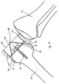
- the invention is based on an embodiment according to the Drawing figure 6 explained in more detail.
- the nail gauge 30 consists essentially of one exactly cuboid contact block 31.
- a stop tab 32 On the dorsal side (in the Drawing figure below) is a stop tab 32 which the only touches rear condyle rollers 39, 39 'at points A and B.
- the stop tab 32 with the contact block is over a Threaded spindle 35 connected, which with a knurled screw 43 as Gear mechanism works together so that the distance of the Stop tab 32 can be varied from the system block 31, such that the Nail gauge 30 in the manner of a slide gauge for size determination and - definition of the femoral part of the artificial knee joint serves.
- the points A and B form two points for the targeted stable three-point system.
- the present system has a wedge 46, which in the arrow A indicated direction between the stop tab 32 and the lateral Femoral condyle 39 'is pushed. This will make the lateral femoral condyle 39 'raised, because there is a slight rotation around point A, namely the point of contact between the medial condyle 39 and the Stop tab 32 is executed. This rotation movement offers the Compensation for the inclination of the frontal resection surface on the tibia. The contact point B is thus shifted from the stop tab 32 to the Wedge 46.
- the angle ⁇ is preferably in the range from 3 to 5 ° and thus corresponds to the Inclination of the horizontal resection surface on the tibia.
Landscapes
- Health & Medical Sciences (AREA)
- Surgery (AREA)
- Life Sciences & Earth Sciences (AREA)
- Biomedical Technology (AREA)
- Medical Informatics (AREA)
- Oral & Maxillofacial Surgery (AREA)
- Nuclear Medicine, Radiotherapy & Molecular Imaging (AREA)
- Transplantation (AREA)
- Physical Education & Sports Medicine (AREA)
- Engineering & Computer Science (AREA)
- Orthopedic Medicine & Surgery (AREA)
- Heart & Thoracic Surgery (AREA)
- Dentistry (AREA)
- Molecular Biology (AREA)
- Animal Behavior & Ethology (AREA)
- General Health & Medical Sciences (AREA)
- Public Health (AREA)
- Veterinary Medicine (AREA)
- Prostheses (AREA)
- Surgical Instruments (AREA)
- Memory System Of A Hierarchy Structure (AREA)
- Orthopedics, Nursing, And Contraception (AREA)
Description
- Fig. 1
- eine Frontalansicht auf die Nagellehre, aufgesetzt auf die Kondylen des natürlichen Kniegelenkes,
- Fig. 2
- die Ansicht auf das teilresezierte natürliche Kniegelenk von medial mit aufgesetzter Sägelehre,
- Fig. 3
- die Frontalaufsicht auf die am Femurstumpf befestigte Sägelehre,
- Fig. 4
- die Ansicht von medial auf die Nagellehre, fixiert auf der horizontalen Anlagefläche des Femurs, und
- Fig. 5
- die Ansicht von medial auf das natürliche Kniegelenk, vorbereitet zur Herstellung der horizontalen Anlagefläche.
Claims (4)
- System zur Rekonstruktion der natürlichen Torquiertheit zwischen dem natürlichen Knie und dem Bereich der natürlichen Hüfte in einer Anordnung zwischen einem künstlichen Kniegelenk und dem Bereich der natürlichen Hüfte nach teilweiser Resektion der natürlichen Kondylen des Kniegelenks und Anlage eines Femurteils des künstlichen Kniegelenks vorbestimmter Größe an den Resektionsflächen des Femurknochens, aufweisendeine Nagellehre (30) mit einem exakt quaderförmigen Anlageblock (31), der an seiner von ventral gesehenen Stirnfläche einen davon abragenden, femurwärts weisenden Schenkel, der an seinem Ende einen Femurkontaktfühler in Form eines senkrecht auf dem Schenkel stehenden Bolzens zur ventral gelegenen punktförmigen Auflage (C) auf dem Femur (10) hält, und an seiner von dorsal gesehenen Stimfläche mindestens eine davon abragende, femurwärts weisende Anschlagslasche (32) zur jeweils dorsal gelegenen punktförmigen Anlage (A, B) an beiden dorsalen Femurkondylenrollen (39, 39') aufweist, wobei der Anlageblock (31) durch Bohrungspaare (33, 34) durchsetzt ist, deren Anordnung die jeweilige Größe des Femurteils repräsentiert, durch welche Fixationsnägel setzbar sind, welche den Anlageblock (31) in seiner Lage auf dem Femur (10) sichert, und wobei der Anlageblock (31) von diesem unter Zurückbelassung der Fixationsnägel abziehbar ist, undeine Sägelehre mit identischer Grundform wie der Anlageblock (31) der Nagellehre (30) und mit identischer Anordnung der Bohrungspaare in dem Anlageblock (31), welche auf die Fixationsnägel setzbar ist, so daß ihre Stirnseiten die übrigen Resektionsebenen (ventral, dorsal, diagonal) festlegen, zusätzlich aufweisend einen Keil mit einem Keilwinkel α, der zwischen die laterale Kondylenrolle (39') und Anschlagslasche (32) schiebbar ist zur Kompensation eine Torquiertheit des Femurknochens.
- System nach Anspruch 1, bei dem der Keilwinkel α im Bereich 3° ≤ α ≤ 5° liegt.
- System nach Anspruch 1 oder 2, bei dem die dorsal gelegene Anschlagslasche (32) und der ventral gelegene Schenkel (37) der Nagellehre (30) mittels eines Getriebemechanismus (35, 43) verbunden sind, mittels dessen ihr Abstand voneinander variiert werden kann.
- System nach einem der Ansprüche 1 bis 3, bei dem dorsal zwei Anschlagslaschen in Form zweier Schenkel vorgesehen sind, die in einer Ebene liegen.
Applications Claiming Priority (3)
| Application Number | Priority Date | Filing Date | Title |
|---|---|---|---|
| DE1997153236 DE19753236C1 (de) | 1997-04-18 | 1997-12-01 | System zur Rekonstruktion der Torquiertheit zwischen dem natürlichen Knie und dem Bereich der natürlichen Hüfte |
| DE19753236 | 1997-12-01 | ||
| PCT/EP1998/005837 WO1999027860A1 (de) | 1997-12-01 | 1998-09-15 | System zur rekonstruktion der torquiertheit zwischen dem natürlichen knie und dem bereich der natürlichen hüfte |
Publications (2)
| Publication Number | Publication Date |
|---|---|
| EP1035802A1 EP1035802A1 (de) | 2000-09-20 |
| EP1035802B1 true EP1035802B1 (de) | 2004-04-07 |
Family
ID=7850386
Family Applications (1)
| Application Number | Title | Priority Date | Filing Date |
|---|---|---|---|
| EP98950033A Expired - Lifetime EP1035802B1 (de) | 1997-12-01 | 1998-09-15 | System zur rekonstruktion der torquiertheit zwischen dem natürlichen knie und dem bereich der natürlichen hüfte |
Country Status (7)
| Country | Link |
|---|---|
| US (1) | US6413261B1 (de) |
| EP (1) | EP1035802B1 (de) |
| JP (1) | JP2001524344A (de) |
| AT (1) | ATE263509T1 (de) |
| DE (1) | DE59811157D1 (de) |
| ES (1) | ES2218857T3 (de) |
| WO (1) | WO1999027860A1 (de) |
Families Citing this family (16)
| Publication number | Priority date | Publication date | Assignee | Title |
|---|---|---|---|---|
| US7635390B1 (en) | 2000-01-14 | 2009-12-22 | Marctec, Llc | Joint replacement component having a modular articulating surface |
| US7547307B2 (en) | 2001-02-27 | 2009-06-16 | Smith & Nephew, Inc. | Computer assisted knee arthroplasty instrumentation, systems, and processes |
| US7708741B1 (en) | 2001-08-28 | 2010-05-04 | Marctec, Llc | Method of preparing bones for knee replacement surgery |
| AU2003217389B2 (en) | 2002-02-11 | 2008-10-30 | Smith & Nephew, Inc. | Image-guided fracture reduction |
| US6916324B2 (en) * | 2003-02-04 | 2005-07-12 | Zimmer Technology, Inc. | Provisional orthopedic prosthesis for partially resected bone |
| US7862570B2 (en) | 2003-10-03 | 2011-01-04 | Smith & Nephew, Inc. | Surgical positioners |
| US7764985B2 (en) | 2003-10-20 | 2010-07-27 | Smith & Nephew, Inc. | Surgical navigation system component fault interfaces and related processes |
| AU2004291146B2 (en) | 2003-11-14 | 2011-08-25 | Smith & Nephew, Inc. | Adjustable surgical cutting systems |
| US7641660B2 (en) | 2004-03-08 | 2010-01-05 | Biomet Manufacturing Corporation | Method, apparatus, and system for image guided bone cutting |
| JP2007531596A (ja) | 2004-03-31 | 2007-11-08 | スミス アンド ネフュー インコーポレーテッド | 基準アレイ入力装置を提供する方法及び装置 |
| EP1737375B1 (de) | 2004-04-21 | 2021-08-11 | Smith & Nephew, Inc | Computerunterstützte navigationssysteme für die schulter-arthroplastie |
| WO2006091704A1 (en) | 2005-02-22 | 2006-08-31 | Smith & Nephew, Inc. | In-line milling system |
| EP2713960B1 (de) * | 2011-06-01 | 2017-03-22 | Smith & Nephew, Inc. | Patientenspezifisches instrument |
| FR2999070B1 (fr) * | 2012-12-11 | 2015-11-20 | Ostesys | Systeme pour couper partiellement un os |
| CN112206525B (zh) * | 2020-09-30 | 2022-04-29 | 深圳市瑞立视多媒体科技有限公司 | Ue4引擎中手拧虚拟物品的信息处理方法和装置 |
| KR102743838B1 (ko) * | 2021-10-26 | 2024-12-18 | 동국대학교 산학협력단 | 관절 운동 계측 시스템 |
Family Cites Families (9)
| Publication number | Priority date | Publication date | Assignee | Title |
|---|---|---|---|---|
| US5047058A (en) * | 1988-04-08 | 1991-09-10 | Smith & Nephew Richards, Inc. | System of inserts for the tibial component of a knee prosthesis |
| DE4141757C1 (de) | 1991-12-18 | 1993-07-15 | Eska Medical Gmbh & Co, 2400 Luebeck, De | |
| US5364401A (en) * | 1992-10-08 | 1994-11-15 | Wright Medical Technology, Inc. | External alignment system for preparing a femur for an implant |
| US5417694A (en) * | 1993-11-08 | 1995-05-23 | Smith & Nephew Richards Inc. | Distal femoral cutting guide apparatus with anterior or posterior referencing for use in knee joint replacement surgery |
| US5486178A (en) * | 1994-02-16 | 1996-01-23 | Hodge; W. Andrew | Femoral preparation instrumentation system and method |
| DE4423717C1 (de) | 1994-07-08 | 1996-01-04 | Eska Medical Gmbh & Co | Vorrichtung zur Festlegung von Resektionsflächen am Femur und an der Tibia zur Vorbereitung einer Implantation einer Kniegelenkstotalendoprothese |
| FR2726178B1 (fr) * | 1994-10-27 | 1997-03-28 | Impact | Instrumentation ancillaire femorale pour l'implantation d'une prothese unicompartimentale du genou |
| DE19716300C1 (de) | 1997-04-18 | 1998-10-08 | Eska Implants Gmbh & Co | System zur Abbildung der natürlichen Torquiertheit zwischen den Kondylen des natürlichen Kniegelenks und dem Gelenkkopf des natürlichen Hüftgelenkes |
| US5916220A (en) * | 1998-02-02 | 1999-06-29 | Medidea, Llc | Bone cutting guide and method to accommodate different-sized implants |
-
1998
- 1998-09-15 EP EP98950033A patent/EP1035802B1/de not_active Expired - Lifetime
- 1998-09-15 WO PCT/EP1998/005837 patent/WO1999027860A1/de not_active Ceased
- 1998-09-15 JP JP2000522849A patent/JP2001524344A/ja active Pending
- 1998-09-15 DE DE59811157T patent/DE59811157D1/de not_active Expired - Lifetime
- 1998-09-15 ES ES98950033T patent/ES2218857T3/es not_active Expired - Lifetime
- 1998-09-15 AT AT98950033T patent/ATE263509T1/de not_active IP Right Cessation
-
2000
- 2000-06-01 US US09/585,145 patent/US6413261B1/en not_active Expired - Fee Related
Also Published As
| Publication number | Publication date |
|---|---|
| DE59811157D1 (de) | 2004-05-13 |
| WO1999027860A1 (de) | 1999-06-10 |
| EP1035802A1 (de) | 2000-09-20 |
| JP2001524344A (ja) | 2001-12-04 |
| US6413261B1 (en) | 2002-07-02 |
| ATE263509T1 (de) | 2004-04-15 |
| ES2218857T3 (es) | 2004-11-16 |
Similar Documents
| Publication | Publication Date | Title |
|---|---|---|
| DE4423717C1 (de) | Vorrichtung zur Festlegung von Resektionsflächen am Femur und an der Tibia zur Vorbereitung einer Implantation einer Kniegelenkstotalendoprothese | |
| DE69531184T2 (de) | Femorales Hilfsgerät zur Implantation einer einseitigen Knieprothese | |
| DE69635956T2 (de) | Knochenschneideführungseinheit zur verwendung beim implantieren von gelenkprothesenkomponenten | |
| DE69630776T2 (de) | Instrument zur tibiaresektion | |
| DE3688207T2 (de) | Chirurgische Instrumente. | |
| EP0928172B1 (de) | Stiellose kniegelenkendoprothese | |
| EP1709914B1 (de) | Bänderspannvorrichtung mit Schnittlehre | |
| EP0919195B1 (de) | Instrumentenbaukasten für Kniegelenkprothesen | |
| DE3787491T2 (de) | Femurkopf-Osteotomielehre für Kniegelenkimplantate. | |
| DE69324233T2 (de) | Externes ausrichtsystem | |
| DE69518077T3 (de) | Schneidgerät für die femorale interkondyläre nut einer von hinten stabilisierten knieprothese | |
| EP2747673B1 (de) | Schneidführung zum erzeugen einer aussenkontur für eine gelenkendoprothese | |
| EP1304964A1 (de) | Vorrichtung zur ausrichtung einer führungsschablone | |
| DE602005003462T2 (de) | Hilfsanordnung zur implantation von knieprothesen | |
| DE102010013258A1 (de) | Vorrichtung zur Positionierung von Schnittführungselementen | |
| EP1035802A1 (de) | System zur rekonstruktion der torquiertheit zwischen dem natürlichen knie und dem bereich der natürlichen hüfte | |
| EP3242637B1 (de) | Lehre für die bestimmung einer für einen patienten passenden implantatgrösse des femurimplantats einer knie-endoprothese | |
| DE29906909U1 (de) | Femurschlitten | |
| DE69821080T2 (de) | Gerät zur Durchtrennung des Femurs zum Einsetzen einer Kniegelenkprothese | |
| DE60206772T2 (de) | Führung zur lokalisierung der resektionsflächen des femur | |
| CH704563B1 (de) | Patientenspezifischer Proberepositionsblock. | |
| EP1309296B1 (de) | Vorrichtung zur optimierung einer knie-endoprothese | |
| EP4311506A2 (de) | Chirurgisches instrument und chirurgisches instrumentensystem | |
| DE69316362T2 (de) | Instrument zur Vorbereitung eines distalen Oberschenkelknochens | |
| DE19716300C1 (de) | System zur Abbildung der natürlichen Torquiertheit zwischen den Kondylen des natürlichen Kniegelenks und dem Gelenkkopf des natürlichen Hüftgelenkes |
Legal Events
| Date | Code | Title | Description |
|---|---|---|---|
| PUAI | Public reference made under article 153(3) epc to a published international application that has entered the european phase |
Free format text: ORIGINAL CODE: 0009012 |
|
| 17P | Request for examination filed |
Effective date: 19991112 |
|
| AK | Designated contracting states |
Kind code of ref document: A1 Designated state(s): AT CH DE ES FR GB IT LI |
|
| GRAP | Despatch of communication of intention to grant a patent |
Free format text: ORIGINAL CODE: EPIDOSNIGR1 |
|
| GRAS | Grant fee paid |
Free format text: ORIGINAL CODE: EPIDOSNIGR3 |
|
| GRAA | (expected) grant |
Free format text: ORIGINAL CODE: 0009210 |
|
| AK | Designated contracting states |
Kind code of ref document: B1 Designated state(s): AT CH DE ES FR GB IT LI |
|
| REG | Reference to a national code |
Ref country code: GB Ref legal event code: FG4D Free format text: NOT ENGLISH |
|
| REG | Reference to a national code |
Ref country code: CH Ref legal event code: EP |
|
| REG | Reference to a national code |
Ref country code: CH Ref legal event code: NV Representative=s name: R. A. EGLI & CO. PATENTANWAELTE |
|
| REF | Corresponds to: |
Ref document number: 59811157 Country of ref document: DE Date of ref document: 20040513 Kind code of ref document: P |
|
| GBT | Gb: translation of ep patent filed (gb section 77(6)(a)/1977) |
Effective date: 20040802 |
|
| REG | Reference to a national code |
Ref country code: ES Ref legal event code: FG2A Ref document number: 2218857 Country of ref document: ES Kind code of ref document: T3 |
|
| ET | Fr: translation filed | ||
| PLBE | No opposition filed within time limit |
Free format text: ORIGINAL CODE: 0009261 |
|
| STAA | Information on the status of an ep patent application or granted ep patent |
Free format text: STATUS: NO OPPOSITION FILED WITHIN TIME LIMIT |
|
| 26N | No opposition filed |
Effective date: 20050110 |
|
| PGFP | Annual fee paid to national office [announced via postgrant information from national office to epo] |
Ref country code: GB Payment date: 20050902 Year of fee payment: 8 |
|
| PGFP | Annual fee paid to national office [announced via postgrant information from national office to epo] |
Ref country code: FR Payment date: 20050920 Year of fee payment: 8 |
|
| PGFP | Annual fee paid to national office [announced via postgrant information from national office to epo] |
Ref country code: ES Payment date: 20050927 Year of fee payment: 8 |
|
| PGFP | Annual fee paid to national office [announced via postgrant information from national office to epo] |
Ref country code: IT Payment date: 20060930 Year of fee payment: 9 |
|
| GBPC | Gb: european patent ceased through non-payment of renewal fee |
Effective date: 20060915 |
|
| REG | Reference to a national code |
Ref country code: FR Ref legal event code: ST Effective date: 20070531 |
|
| PG25 | Lapsed in a contracting state [announced via postgrant information from national office to epo] |
Ref country code: GB Free format text: LAPSE BECAUSE OF NON-PAYMENT OF DUE FEES Effective date: 20060915 |
|
| REG | Reference to a national code |
Ref country code: ES Ref legal event code: FD2A Effective date: 20060916 |
|
| PG25 | Lapsed in a contracting state [announced via postgrant information from national office to epo] |
Ref country code: ES Free format text: LAPSE BECAUSE OF NON-PAYMENT OF DUE FEES Effective date: 20060916 |
|
| PG25 | Lapsed in a contracting state [announced via postgrant information from national office to epo] |
Ref country code: FR Free format text: LAPSE BECAUSE OF NON-PAYMENT OF DUE FEES Effective date: 20061002 |
|
| PGFP | Annual fee paid to national office [announced via postgrant information from national office to epo] |
Ref country code: CH Payment date: 20080923 Year of fee payment: 11 |
|
| PGFP | Annual fee paid to national office [announced via postgrant information from national office to epo] |
Ref country code: AT Payment date: 20080919 Year of fee payment: 11 |
|
| PG25 | Lapsed in a contracting state [announced via postgrant information from national office to epo] |
Ref country code: IT Free format text: LAPSE BECAUSE OF NON-PAYMENT OF DUE FEES Effective date: 20070915 |
|
| REG | Reference to a national code |
Ref country code: CH Ref legal event code: PL |
|
| PG25 | Lapsed in a contracting state [announced via postgrant information from national office to epo] |
Ref country code: AT Free format text: LAPSE BECAUSE OF NON-PAYMENT OF DUE FEES Effective date: 20090915 |
|
| PG25 | Lapsed in a contracting state [announced via postgrant information from national office to epo] |
Ref country code: LI Free format text: LAPSE BECAUSE OF NON-PAYMENT OF DUE FEES Effective date: 20090930 Ref country code: CH Free format text: LAPSE BECAUSE OF NON-PAYMENT OF DUE FEES Effective date: 20090930 |
|
| REG | Reference to a national code |
Ref country code: DE Ref legal event code: R081 Ref document number: 59811157 Country of ref document: DE Owner name: ORTHODYNAMICS GMBH, DE Free format text: FORMER OWNER: ESKA IMPLANTS GMBH & CO.KG, 23556 LUEBECK, DE Effective date: 20110707 |
|
| PGFP | Annual fee paid to national office [announced via postgrant information from national office to epo] |
Ref country code: DE Payment date: 20120927 Year of fee payment: 15 |
|
| REG | Reference to a national code |
Ref country code: DE Ref legal event code: R119 Ref document number: 59811157 Country of ref document: DE Effective date: 20140401 |
|
| PG25 | Lapsed in a contracting state [announced via postgrant information from national office to epo] |
Ref country code: DE Free format text: LAPSE BECAUSE OF NON-PAYMENT OF DUE FEES Effective date: 20140401 |