EP1036424B1 - Configuration d'antenne d'emission pour systeme de surveillance electronique d'article - Google Patents
Configuration d'antenne d'emission pour systeme de surveillance electronique d'article Download PDFInfo
- Publication number
- EP1036424B1 EP1036424B1 EP98965376A EP98965376A EP1036424B1 EP 1036424 B1 EP1036424 B1 EP 1036424B1 EP 98965376 A EP98965376 A EP 98965376A EP 98965376 A EP98965376 A EP 98965376A EP 1036424 B1 EP1036424 B1 EP 1036424B1
- Authority
- EP
- European Patent Office
- Prior art keywords
- transmitting
- antenna system
- coils
- modes
- tuning
- Prior art date
- Legal status (The legal status is an assumption and is not a legal conclusion. Google has not performed a legal analysis and makes no representation as to the accuracy of the status listed.)
- Expired - Lifetime
Links
Images


Classifications
-
- G—PHYSICS
- G08—SIGNALLING
- G08B—SIGNALLING SYSTEMS, e.g. PERSONAL CALLING SYSTEMS; ORDER TELEGRAPHS; ALARM SYSTEMS
- G08B13/00—Burglar, theft or intruder alarms
- G08B13/22—Electrical actuation
- G08B13/24—Electrical actuation by interference with electromagnetic field distribution
- G08B13/2402—Electronic Article Surveillance [EAS], i.e. systems using tags for detecting removal of a tagged item from a secure area, e.g. tags for detecting shoplifting
- G08B13/2465—Aspects related to the EAS system, e.g. system components other than tags
- G08B13/2468—Antenna in system and the related signal processing
- G08B13/2477—Antenna or antenna activator circuit
-
- G—PHYSICS
- G08—SIGNALLING
- G08B—SIGNALLING SYSTEMS, e.g. PERSONAL CALLING SYSTEMS; ORDER TELEGRAPHS; ALARM SYSTEMS
- G08B13/00—Burglar, theft or intruder alarms
- G08B13/22—Electrical actuation
- G08B13/24—Electrical actuation by interference with electromagnetic field distribution
- G08B13/2402—Electronic Article Surveillance [EAS], i.e. systems using tags for detecting removal of a tagged item from a secure area, e.g. tags for detecting shoplifting
- G08B13/2465—Aspects related to the EAS system, e.g. system components other than tags
- G08B13/2468—Antenna in system and the related signal processing
- G08B13/2471—Antenna signal processing by receiver or emitter
-
- G—PHYSICS
- G08—SIGNALLING
- G08B—SIGNALLING SYSTEMS, e.g. PERSONAL CALLING SYSTEMS; ORDER TELEGRAPHS; ALARM SYSTEMS
- G08B13/00—Burglar, theft or intruder alarms
- G08B13/22—Electrical actuation
- G08B13/24—Electrical actuation by interference with electromagnetic field distribution
- G08B13/2402—Electronic Article Surveillance [EAS], i.e. systems using tags for detecting removal of a tagged item from a secure area, e.g. tags for detecting shoplifting
- G08B13/2465—Aspects related to the EAS system, e.g. system components other than tags
- G08B13/2468—Antenna in system and the related signal processing
- G08B13/2474—Antenna or antenna activator geometry, arrangement or layout
-
- H—ELECTRICITY
- H01—ELECTRIC ELEMENTS
- H01Q—ANTENNAS, i.e. RADIO AERIALS
- H01Q11/00—Electrically-long antennas having dimensions more than twice the shortest operating wavelength and consisting of conductive active radiating elements
- H01Q11/12—Resonant antennas
- H01Q11/14—Resonant antennas with parts bent, folded, shaped or screened or with phasing impedances, to obtain desired phase relation of radiation from selected sections of the antenna or to obtain desired polarisation effect
-
- H—ELECTRICITY
- H01—ELECTRIC ELEMENTS
- H01Q—ANTENNAS, i.e. RADIO AERIALS
- H01Q7/00—Loop antennas with a substantially uniform current distribution around the loop and having a directional radiation pattern in a plane perpendicular to the plane of the loop
- H01Q7/005—Loop antennas with a substantially uniform current distribution around the loop and having a directional radiation pattern in a plane perpendicular to the plane of the loop with variable reactance for tuning the antenna
-
- H—ELECTRICITY
- H01—ELECTRIC ELEMENTS
- H01Q—ANTENNAS, i.e. RADIO AERIALS
- H01Q7/00—Loop antennas with a substantially uniform current distribution around the loop and having a directional radiation pattern in a plane perpendicular to the plane of the loop
- H01Q7/04—Screened antennas
Definitions
- This invention relates to the field of electronic article surveillance systems, and in particular, to optimizing transmitter to antenna coupling for interlaced transmitter phases.
- EAS systems employ magnetic markers, also referred to as tags, which are placed on articles or products which are monitored to prevent unauthorized removal from a restricted space, for example a retail store or a library. Egress from the space is restricted to a lane or path into which a radio frequency interrogating signal is transmitted. This area is referred to as the interrogation zone. If the marker or tag is present in or on the article, and the marker or tag has not been deactivated, the marker or tag acts as a transponder and generates a return signal which can be identified by a receiver. The receiver can initiate an audible alarm, for example, or trigger other protective measures.
- the transmitting and receiving antennas are mounted in floors, walls, ceilings or free standing pylons. These are necessarily fixed mounting positions.
- the articles on the other hand, may be carried through the field of the interrogating signal in any orientation, and accordingly, so may the tags or markers.
- a pylon structure P has an upstanding portion on which two rectangular transmitting loops A and B are mounted with adjacent legs at height h above the floor.
- the loops are driven by current flowing in the same direction, for example clockwise as indicated by arrows I A and I B in Figure 5(a)
- the current D in the bottom leg of loop A and the current E in the top leg of loop B flow in opposite directions. Accordingly, the respective fields generated by currents D and E mostly cancel out one another.
- the overall effect is that of a single, large rectangular loop.
- a single rectangular loop transmitter, the in-phase configuration, will provide substantial horizontal magnetic field, but a significantly lower or even zero valued vertical component, especially at the central height h of the interrogation zone.
- the vertical magnetic field becomes stronger but the horizontal component becomes weaker or even zero valued. Therefore it is desirable to interlace the transmitter phases, that is, alternate transmissions from the two antenna configurations, to maximize the system performance for all orientations of markers in the interrogation zone.
- An ULTRA MAX ® marker or tag is the kind of tag having two components.
- One component is an amorphous material which responds to an interrogating signal at a resonant frequency, for example 58 KHz, in the presence of a magnetic bias.
- the other component is a magnetic material which provides the magnetic bias making possible the resonant response of the amorphous material.
- the marker frequency also varies with magnetic field.
- the resonant frequency of a linear ULTRA MAX ® marker can shift up or down by about three to four hundred Hz in the vertical orientation due to the earth's magnetic field.
- the term ULTRA MAX ® is a registered trademark of Sensormatic Electronics Corporation. Therefore, it is also desirable to transmit two frequencies, instead of one frequency, to increase the effective peak performance of the marker.
- the additional frequencies chosen are typically about two to three hundred Hz from the center operating frequency. Consequently, the transmitter of such a dual frequency system can not be optimized.
- US 4,679,046 discloses a transmitter antenna system comprising an antenna circuit having a plurality of transmitting coils, wherein a first coil is divided in an upper loop and a lower loop. Both loops forming a figure-8 configuration and are connected and continuous. A second loop arranged is in the circumpherence of the 8 configuration of the first loop and produces a field different from the first figure-8 loop.
- a third antenna loop is also disclosed to create a spherically polarized field.
- US 4,679,046 does not disclose to switch two separate loops, that they form together either a figure-8 configuration or a rectangular regulation and does not disclose a compensation coil which is field-coupled for tuning the two transmitter coils for tuning for optimized transmitter current in the two (in-phase and out-of-phase) modes of operation.
- US 4,647,931 discloses an interrogation system comprising an interrogator transmitting a first frequency and a second frequency depending on a preselected mode.
- WO 96/41399 discloses the incorporation of a compensation coil for eliminating the effect of a first coil in a second coil in the far field distance. Accordingly, there has been a long felt need to provide an interlaced, dual frequency EAS system which can be optimized for peak performance and reliability.
- An interlaced, dual frequency EAS system which can be optimized for peak performance and reliability in accordance with the inventive arrangements satisfies this long felt need,
- a novel transmitter antenna design allows for maximum coverage of an interlaced, dual frequency EAS system for all marker orientations.
- a single loop with capacitor is added to the outer perimeter of the transmitter pair.
- such an added loop does not influence the transmitter, due to a net zero coupling between the added loop and the "figure 8" transmitter configuration.
- the added loop has a significant coupling with the transmitter pair.
- the tuning frequencies of the two modes can be independently set.
- the frequencies are advantageous to be set by about two to three hundred Hz from the center operational frequency.
- the EAS system performance is not subject to fluctuation due to production variation and like factors.
- An EAS system can be driven in either an in-phase or "figure-8" mode with proper tuning for maximum transmitter current. As a result, the system pick performance can be enhanced significantly.
- An antenna system for an electronic article surveillance system is claimed, in accordance with claim 1.
- One of the first and second modes of operation is as an in-phase rectangular loop and the other of the first and second modes of operation is as a "figure-8".
- the compensation coil encircles the first and second transmitting coils.
- the system can further comprise means for supplying respective signals for energizing the first and second transmitting loops at said first and second resonant frequencies and in an interlaced manner.
- a method for tuning an antenna system for an electronic article surveillance system in accordance with claim 6.
- the method can further comprise the step of encircling the first and second transmitting coils with the compensation loop.
- the method comprises the steps of: transmitting from a "figure-8" antenna configuration in one of the first and second modes of operation; and, transmitting from a rectangular loop antenna configuration in the other of the first and second modes of operation.
- the method further comprises the steps of: firstly tuning the transmitting coils for operation is the "figure-8" antenna configuration; and, secondly tuning the compensation coil for operation in the rectangular loop antenna configuration.
- the method further comprises the step of supplying respective signals for energizing the first and second transmitting coils at the first and second resonant frequencies in an interlaced manner.
- Figure 2 is a plot of vertical component field strength illustrating the coupling for the "figure-8" mode. The vertical coupling is maximum at the center height, while two weak spots exist at heights about 20 inches lower and higher than the central line, which is well covered by the in-phase components.
- the transmitter must be tuned to provide sufficient current for proper operation. However, it has thus far been impossible to have the transmitter pair be in-tune for both in-phase and "figure-8" modes, due to existing mutual coupling of the two transmitter coils.
- the difference in resonant frequencies of the two transmitter phases typically ranges between 3 kHz to 4 kHz. Therefore, maximum transmitter efficiency could not be achieved for both phases.
- the first step is to tune the "figure-8" mode to resonate at the designated operating frequency, for example 58 kHz.
- the resonant frequency of the in-phase mode shifts upwardly to 61.3 kHz.
- a compensation coil or loop 16 having one, two or a few turns can advantageously be wrapped around the outer perimeter of the pair of transmitter coils 12 and 14 and terminated with a H capacitor. With a properly chosen capacitor value, the in-phase resonance can be adjusted back down to 58 kHz, due to the significant coupling between the compensation coil and the in-phase coil assemblies.
- the addition of the compensation coil does not affect the tuning of the "figure-8" mode because their mutual coupling is essentially zero. As a result, the modified coil assembly is tuned for both modes for maximum system detection.
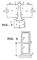
- FIG. 3 An exemplary transmitter-antenna circuit 10 in accordance with the inventive arrangements is shown in Figure 3 .
- Inductors L 1 and L 2 represent the inductance of the two transmitter coils 12 and 14.
- Resistors R 1 and R 2 represent the respective series resistances of the transmitter coils 12 and 14.
- the capacitors C 1 and C 2 are used to tune the "figure-8" resonant frequency to the operating system frequency, for example 58 kHz.
- V S1 and R S1 represent the output voltage and internal source resistance for one of the antenna drivers.
- V S2 and R S2 represent the output voltage and internal source resistance for the other of the antenna drivers.
- the compensation loop or coil 16 needed for in-phase tuning is represented by inductor L c , resistor R c and capacitor C C .
- the coupling between the transmitter coils 12 and 14 is represented by k 12 .
- the coupling between the compensation coil 16 and each of the transmitter coils 12 and 14 is represented by k 1C and k 2C .
- Typical component values are shown in the following Tables.
- Table 1 Transmitter coils R s1 L 1 C 1 R 1 k 12 1 ⁇ 350 ⁇ H 20 nF 2.96 ⁇ -0.053
Landscapes
- Engineering & Computer Science (AREA)
- Physics & Mathematics (AREA)
- Signal Processing (AREA)
- Automation & Control Theory (AREA)
- Computer Security & Cryptography (AREA)
- Electromagnetism (AREA)
- General Physics & Mathematics (AREA)
- Burglar Alarm Systems (AREA)
- Variable-Direction Aerials And Aerial Arrays (AREA)
- Near-Field Transmission Systems (AREA)
- Transmitters (AREA)
- Radar Systems Or Details Thereof (AREA)
Abstract
Claims (12)
- Système d'antenne pour système électronique de surveillance d'articles, comprenant une pluralité de bobines d'émission,
une première bobine d'émission accordable (12) et une seconde bobine d'émission accordable (14), étant chacune des bobines séparées (12, 14), ledit système étant caractérisé en ce que qu'il est agencé pour un premier mode de fonctionnement en phase et un second mode de fonctionnement en déphasage, lesdites bobines d'émission (12, 14) étant couplées par champ l'une à l'autre de telle sorte que l'accord dudit système d'antenne pour l'un desdits modes de fonctionnement désaccorde ledit système d'antenne pour l'autre mode de fonctionnement ; et,
une bobine de compensation accordable (16) couplée par champ à chacune desdites première et seconde bobines d'émission (12, 14), ladite bobine de compensation accordable (16) permettant d'accorder ledit système d'antenne pour un courant d'émetteur optimisé pour le fonctionnement dans l'un desdits modes à une première fréquence de résonance, et en dépit dudit désaccord, permettant d'accorder ledit système d'antenne pour le fonctionnement dans l'autre desdits modes à une seconde fréquence de résonance indépendamment dudit accord pour ledit premier mode de fonctionnement. - Système d'antenne selon la revendication 1, dans lequel l'un desdits premier et second modes de fonctionnement est comme une configuration de bobine rectangulaire en phase et l'autre desdits premier et second modes de fonctionnement est comme une configuration de bobine "en forme de 8" formée par les première et seconde bobines d'émission (12, 14).
- Système d'antenne selon la revendication 1 ou 2, dans lequel ladite bobine de compensation (16) encercle lesdites première et seconde bobines d'émission (12, 14).
- Système d'antenne selon l'une quelconque des revendications précédentes, comprenant en outre un moyen d'émission pour fournir des signaux respectifs servant à exciter lesdites première et seconde bobines d'émission (12, 14) auxdites première et seconde fréquences de résonance et de manière entrelacée.
- Système d'antenne selon l'une quelconque des revendications précédentes, dans lequel ledit couplage par champ de ladite bobine de compensation (16) avec lesdites première et seconde bobines d'émission (12, 14) se supprime sensiblement de lui-même dans l'un desdits premier et second modes de fonctionnement dans lequel ledit système d'antenne est accordé sur ladite première fréquence de résonance.
- Procédé d'accord d'un système d'antenne pour système électronique de surveillance d'articles, le système d'antenne ayant une pluralité de bobines d'émission (12, 14),
caractérisé par
des première et seconde bobines d'émission séparées couplées par champ l'une à l'autre et le couplage par champ d'une bobine de compensation (16) à chacune desdites première et seconde bobines d'émission (12, 14) ; l'accord des première et seconde bobines d'émission (12, 14) pour un premier mode de fonctionnement à une première fréquence de résonance, dans lequel les bobines fonctionnent en phase en en déphasage ; et
l'accord de ladite bobine de compensation (16) pour un fonctionnement à une seconde fréquence de résonance différente de ladite première fréquence de résonance. - Procédé selon la revendication 6, comprenant l'étape de réglage desdites première et seconde fréquences de résonance sur une fréquence de résonance commune.
- Procédé selon la revendication 6, comprenant l'étape de réglage desdites première et seconde fréquences de résonance sur des fréquences de résonance différentes.
- Procédé selon la revendication 6, comprenant l'étape d'encerclement desdites première et seconde bobines d'émission (12, 14) avec ladite bobine de compensation (16).
- Procédé selon la revendication 6, comprenant les étapes suivantes : émission à partir d'une configuration d'antenne en "forme de 8" formée par lesdites bobines (12, 14) dans un mode de déphasage étant l'un desdits premier et second modes de fonctionnement ; et
émission à partir d'une configuration d'antenne en boucle rectangulaire formée par lesdites bobines (12, 14) dans un mode en phase étant l'autre desdits premier et second modes de fonctionnement. - Procédé selon la revendication 10, comprenant l'étape consistant à : premièrement, accorder lesdites bobines d'émission (12, 14) pour un fonctionnement dans ladite configuration d'antenne en "forme de 8" ; et
deuxièmement, accorder ladite bobine de compensation (16) pour un fonctionnement dans ladite configuration d'antenne en boucle rectangulaire. - Procédé selon l'une quelconque des revendications 6 à 11, comprenant en outre l'étape consistant à fournir des signaux respectifs servant à exciter lesdites première et seconde bobines d'émission (12, 14) auxdites première et seconde fréquences de résonance de manière entrelacée.
Applications Claiming Priority (3)
| Application Number | Priority Date | Filing Date | Title |
|---|---|---|---|
| US08/985,941 US5963173A (en) | 1997-12-05 | 1997-12-05 | Antenna and transmitter arrangement for EAS system |
| US985941 | 1997-12-05 | ||
| PCT/US1998/025249 WO1999030384A1 (fr) | 1997-12-05 | 1998-11-25 | Configuration d'antenne d'emission pour systeme de surveillance electronique d'article |
Publications (3)
| Publication Number | Publication Date |
|---|---|
| EP1036424A1 EP1036424A1 (fr) | 2000-09-20 |
| EP1036424A4 EP1036424A4 (fr) | 2001-01-24 |
| EP1036424B1 true EP1036424B1 (fr) | 2009-11-25 |
Family
ID=25531931
Family Applications (1)
| Application Number | Title | Priority Date | Filing Date |
|---|---|---|---|
| EP98965376A Expired - Lifetime EP1036424B1 (fr) | 1997-12-05 | 1998-11-25 | Configuration d'antenne d'emission pour systeme de surveillance electronique d'article |
Country Status (8)
| Country | Link |
|---|---|
| US (1) | US5963173A (fr) |
| EP (1) | EP1036424B1 (fr) |
| JP (1) | JP4619532B2 (fr) |
| AU (1) | AU747534B2 (fr) |
| BR (1) | BR9813377A (fr) |
| CA (1) | CA2312929C (fr) |
| DE (1) | DE69841329D1 (fr) |
| WO (1) | WO1999030384A1 (fr) |
Families Citing this family (91)
| Publication number | Priority date | Publication date | Assignee | Title |
|---|---|---|---|---|
| US6118378A (en) * | 1997-11-28 | 2000-09-12 | Sensormatic Electronics Corporation | Pulsed magnetic EAS system incorporating single antenna with independent phasing |
| US6388628B1 (en) * | 1998-05-18 | 2002-05-14 | Db Tag, Inc. | Systems and methods for wirelessly projecting power using in-phase current loops |
| US6570541B2 (en) | 1998-05-18 | 2003-05-27 | Db Tag, Inc. | Systems and methods for wirelessly projecting power using multiple in-phase current loops |
| US6166706A (en) * | 1998-11-04 | 2000-12-26 | Checkpoint Systems, Inc. | Rotating field antenna with a magnetically coupled quadrature loop |
| GB9915595D0 (en) * | 1999-07-02 | 1999-09-01 | Sadler Robin W | Identification apparatus for reading moving tags in passageways |
| US7000514B2 (en) | 2001-07-27 | 2006-02-21 | Sd3, Llc | Safety systems for band saws |
| US7225712B2 (en) | 2000-08-14 | 2007-06-05 | Sd3, Llc | Motion detecting system for use in a safety system for power equipment |
| US20020017179A1 (en) | 2000-08-14 | 2002-02-14 | Gass Stephen F. | Miter saw with improved safety system |
| US7024975B2 (en) | 2000-08-14 | 2006-04-11 | Sd3, Llc | Brake mechanism for power equipment |
| US7836804B2 (en) | 2003-08-20 | 2010-11-23 | Sd3, Llc | Woodworking machines with overmolded arbors |
| US20050041359A1 (en) | 2003-08-20 | 2005-02-24 | Gass Stephen F. | Motion detecting system for use in a safety system for power equipment |
| US7284467B2 (en) * | 2000-08-14 | 2007-10-23 | Sd3, Llc | Apparatus and method for detecting dangerous conditions in power equipment |
| US7137326B2 (en) | 2000-08-14 | 2006-11-21 | Sd3, Llc | Translation stop for use in power equipment |
| US6945149B2 (en) | 2001-07-25 | 2005-09-20 | Sd3, Llc | Actuators for use in fast-acting safety systems |
| US7610836B2 (en) | 2000-08-14 | 2009-11-03 | Sd3, Llc | Replaceable brake mechanism for power equipment |
| US7827890B2 (en) | 2004-01-29 | 2010-11-09 | Sd3, Llc | Table saws with safety systems and systems to mount and index attachments |
| US7377199B2 (en) | 2000-09-29 | 2008-05-27 | Sd3, Llc | Contact detection system for power equipment |
| US8065943B2 (en) | 2000-09-18 | 2011-11-29 | Sd3, Llc | Translation stop for use in power equipment |
| US6994004B2 (en) | 2000-09-29 | 2006-02-07 | Sd3, Llc | Table saw with improved safety system |
| US7481140B2 (en) | 2005-04-15 | 2009-01-27 | Sd3, Llc | Detection systems for power equipment |
| US7350445B2 (en) | 2003-08-20 | 2008-04-01 | Sd3, Llc | Brake cartridge for power equipment |
| US20030037651A1 (en) | 2001-08-13 | 2003-02-27 | Gass Stephen F. | Safety systems for power equipment |
| US6857345B2 (en) | 2000-08-14 | 2005-02-22 | Sd3, Llc | Brake positioning system |
| US9724840B2 (en) | 1999-10-01 | 2017-08-08 | Sd3, Llc | Safety systems for power equipment |
| US7077039B2 (en) | 2001-11-13 | 2006-07-18 | Sd3, Llc | Detection system for power equipment |
| US7210383B2 (en) | 2000-08-14 | 2007-05-01 | Sd3, Llc | Detection system for power equipment |
| US6880440B2 (en) | 2000-09-29 | 2005-04-19 | Sd3, Llc | Miter saw with improved safety system |
| US7308843B2 (en) | 2000-08-14 | 2007-12-18 | Sd3, Llc | Spring-biased brake mechanism for power equipment |
| US7171879B2 (en) | 2001-07-02 | 2007-02-06 | Sd3, Llc | Discrete proximity detection system |
| US7712403B2 (en) | 2001-07-03 | 2010-05-11 | Sd3, Llc | Actuators for use in fast-acting safety systems |
| US20030056853A1 (en) | 2001-09-21 | 2003-03-27 | Gass Stephen F. | Router with improved safety system |
| US6945148B2 (en) | 2000-09-29 | 2005-09-20 | Sd3, Llc | Miter saw with improved safety system |
| US6920814B2 (en) | 2000-08-14 | 2005-07-26 | Sd3, Llc | Cutting tool safety system |
| US7707920B2 (en) | 2003-12-31 | 2010-05-04 | Sd3, Llc | Table saws with safety systems |
| US6957601B2 (en) * | 2000-08-14 | 2005-10-25 | Sd3, Llc | Translation stop for use in power equipment |
| US8459157B2 (en) | 2003-12-31 | 2013-06-11 | Sd3, Llc | Brake cartridges and mounting systems for brake cartridges |
| US7536238B2 (en) | 2003-12-31 | 2009-05-19 | Sd3, Llc | Detection systems for power equipment |
| US9927796B2 (en) | 2001-05-17 | 2018-03-27 | Sawstop Holding Llc | Band saw with improved safety system |
| US7055417B1 (en) | 1999-10-01 | 2006-06-06 | Sd3, Llc | Safety system for power equipment |
| US8061245B2 (en) | 2000-09-29 | 2011-11-22 | Sd3, Llc | Safety methods for use in power equipment |
| US7290472B2 (en) | 2002-01-14 | 2007-11-06 | Sd3, Llc | Miter saw with improved safety system |
| US7197969B2 (en) | 2001-09-24 | 2007-04-03 | Sd3, Llc | Logic control with test mode for fast-acting safety system |
| US7231856B2 (en) | 2001-06-13 | 2007-06-19 | Sd3, Llc | Apparatus and method for detecting dangerous conditions in power equipment |
| US7472634B2 (en) | 2003-08-20 | 2009-01-06 | Sd3, Llc | Woodworking machines with overmolded arbors |
| US7100483B2 (en) | 2000-08-14 | 2006-09-05 | Sd3, Llc | Firing subsystem for use in a fast-acting safety system |
| US6877410B2 (en) | 2000-09-29 | 2005-04-12 | Sd3, Llc | Miter saw with improved safety system |
| US7353737B2 (en) | 2001-08-13 | 2008-04-08 | Sd3, Llc | Miter saw with improved safety system |
| US7600455B2 (en) | 2000-08-14 | 2009-10-13 | Sd3, Llc | Logic control for fast-acting safety system |
| US7350444B2 (en) | 2000-08-14 | 2008-04-01 | Sd3, Llc | Table saw with improved safety system |
| DE10002311C1 (de) * | 2000-01-20 | 2001-06-13 | Skidata Ag | Kommunikationsendgerät |
| US6826988B2 (en) | 2000-09-29 | 2004-12-07 | Sd3, Llc | Miter saw with improved safety system |
| US6813983B2 (en) | 2000-09-29 | 2004-11-09 | Sd3, Llc | Power saw with improved safety system |
| JP3498716B2 (ja) * | 2001-02-09 | 2004-02-16 | オムロン株式会社 | アンテナ装置 |
| US20030001739A1 (en) * | 2001-06-29 | 2003-01-02 | Robert Clucas | Electronic article surveillance antenna for attachment to a vertical structure |
| US6567050B1 (en) * | 2001-12-17 | 2003-05-20 | Briggs James B | Loop antenna compensator |
| US6590542B1 (en) * | 2001-12-17 | 2003-07-08 | James B. Briggs | Double loop antenna |
| US8321302B2 (en) * | 2002-01-23 | 2012-11-27 | Sensormatic Electronics, LLC | Inventory management system |
| US8339265B2 (en) | 2002-01-09 | 2012-12-25 | Sensormatic Electronics, Llc. | Method of assigning and deducing the location of articles detected by multiple RFID antennae |
| EP1470613A4 (fr) * | 2002-01-09 | 2005-10-05 | Meadwestvaco Corp | Station intelligente utilisant plusieurs antennes r.f. et systeme de gestion de stocks incorporant ladite station. |
| PT102739A (pt) * | 2002-03-13 | 2003-09-30 | Gantle Trading & Services Ld | Sistema de antenas para um dispositivo de leitura de transponder em radiofrequencia |
| US6753821B2 (en) * | 2002-04-22 | 2004-06-22 | Wg Security Products, Inc. | Method and arrangement of antenna system of EAS |
| US6752837B2 (en) | 2002-06-28 | 2004-06-22 | Hewlett-Packard Development Company, L.P. | Security tags with a reversible optical indicator |
| CN100583554C (zh) * | 2003-08-29 | 2010-01-20 | 精工爱普生株式会社 | 环形天线装置 |
| GB0328359D0 (en) * | 2003-12-06 | 2004-01-14 | Telegesis Uk Ltd | Radio frequency antenna |
| US7417599B2 (en) * | 2004-02-20 | 2008-08-26 | 3M Innovative Properties Company | Multi-loop antenna for radio frequency identification (RFID) communication |
| US7347851B1 (en) | 2004-03-09 | 2008-03-25 | Leo B Kriksunov | Needleless hypodermic jet injector apparatus and method |
| US7301459B2 (en) * | 2004-05-11 | 2007-11-27 | Sensormatic Electronics Corporation | Closed loop transmitter control for power amplifier in an EAS system |
| US20070164845A1 (en) * | 2004-12-21 | 2007-07-19 | Checkpoint Systems, Inc. | System and method for monitoring security systems |
| NL1028330C2 (nl) * | 2005-02-18 | 2006-08-21 | Nedap Nv | Smart Shelf. |
| US7750812B2 (en) * | 2005-03-03 | 2010-07-06 | Sensormatic Electronics, Llc. | Apparatus for and method of using an intelligent network and RFID signal router |
| US8316156B2 (en) * | 2006-02-17 | 2012-11-20 | Intel-Ne, Inc. | Method and apparatus for interfacing device drivers to single multi-function adapter |
| US20070296548A1 (en) * | 2006-06-27 | 2007-12-27 | Hall Stewart E | Resonant circuit tuning system using magnetic field coupled reactive elements |
| US7570220B2 (en) * | 2006-06-27 | 2009-08-04 | Sensormatic Electronics Corporation | Resonant circuit tuning system with dynamic impedance matching |
| US7651267B2 (en) * | 2006-08-08 | 2010-01-26 | Ford Global Technologies, Llc | Sensor arrangement and method for using same |
| DE102007018058A1 (de) | 2007-04-17 | 2008-10-23 | Kathrein-Werke Kg | RFID-Antennen-System |
| DE102007018059A1 (de) | 2007-04-17 | 2008-10-23 | Kathrein-Werke Kg | RFID-Antennen-System |
| US7460073B2 (en) | 2007-04-18 | 2008-12-02 | Kathrein-Werke Kg | RFID antenna system |
| US7852268B2 (en) | 2007-04-18 | 2010-12-14 | Kathrein-Werke Kg | RFID antenna system |
| GB2461126B (en) * | 2008-06-25 | 2010-09-29 | Shearwell Data Ltd | Antenna system |
| NZ591383A (en) | 2008-09-04 | 2013-08-30 | Allflex Usa Inc | Combination full-duplex and half-duplex electronic identification tag |
| JP5307241B2 (ja) * | 2009-06-16 | 2013-10-02 | 株式会社ビー・アンド・プラス | 双方向伝送用コイルおよびこれを用いた双方向伝送装置 |
| WO2011044585A1 (fr) * | 2009-10-09 | 2011-04-14 | Allflex Usa, Inc. | Démodulateur hdx |
| NO2486552T3 (fr) * | 2009-10-09 | 2018-01-27 | ||
| ES2776023T3 (es) * | 2009-11-04 | 2020-07-28 | Allflex Usa Inc | Antena de múltiples bucles de transmisión/recepción de cancelación de señal para un lector de identificación de radiofrecuencia |
| FR2954551B1 (fr) * | 2009-12-21 | 2012-08-17 | Commissariat Energie Atomique | Dispositif d'echange de donnees sans contact securise entre un lecteur et une carte |
| US8362956B2 (en) * | 2010-11-18 | 2013-01-29 | Nader Behdad | Electrically small, source direction resolving antennas |
| US20120139730A1 (en) * | 2010-12-03 | 2012-06-07 | Metrologic Instruments, Inc. | Electronic article surveillance system |
| WO2013117994A1 (fr) * | 2012-01-05 | 2013-08-15 | Hid Global Gmbh | Antennes magnétiques compensées par calcul pour différentes fréquences |
| US8849229B2 (en) | 2012-06-01 | 2014-09-30 | Wisconsin Alumni Research Foundation | Electrically small, super directive antennas |
| US9424724B2 (en) | 2013-08-02 | 2016-08-23 | Bibliotheca Rfid Library Systems Ag | Single turn magnetic drive loop for electronic article surveillance |
| CA2980980A1 (fr) * | 2015-04-02 | 2016-10-06 | NTL S.r.l. | Dispositif de detection par radiofrequence anti-vol rfid et/ou rfid/em |
Citations (1)
| Publication number | Priority date | Publication date | Assignee | Title |
|---|---|---|---|---|
| WO1996041399A1 (fr) * | 1995-06-07 | 1996-12-19 | Checkpoint Systems, Inc. | Antenne-cadre d'emision et de reception |
Family Cites Families (13)
| Publication number | Priority date | Publication date | Assignee | Title |
|---|---|---|---|---|
| US3588905A (en) * | 1967-10-05 | 1971-06-28 | John H Dunlavy Jr | Wide range tunable transmitting loop antenna |
| US3683389A (en) * | 1971-01-20 | 1972-08-08 | Corning Glass Works | Omnidirectional loop antenna array |
| US4243980A (en) * | 1978-02-17 | 1981-01-06 | Lichtblau G J | Antenna system for electronic security installations |
| US4260990A (en) * | 1979-11-08 | 1981-04-07 | Lichtblau G J | Asymmetrical antennas for use in electronic security systems |
| US4647931A (en) | 1984-11-29 | 1987-03-03 | Rca Corporation | Dual frequency identification system |
| GB2180123B (en) * | 1984-12-21 | 1989-01-18 | Senezco Limited | Transponder systems |
| US4675658A (en) * | 1985-09-17 | 1987-06-23 | Allied Corporation | System including tuned AC magnetic field transmit antenna and untuned AC magnetic field receive antenna |
| US4658241A (en) * | 1985-09-17 | 1987-04-14 | Allied Corporation | Surveillance system including transmitter and receiver synchronized by power line zero crossings |
| US5103234A (en) * | 1987-08-28 | 1992-04-07 | Sensormatic Electronics Corporation | Electronic article surveillance system |
| US5103235A (en) * | 1988-12-30 | 1992-04-07 | Checkpoint Systems, Inc. | Antenna structure for an electronic article surveillance system |
| US5023600A (en) * | 1990-04-10 | 1991-06-11 | Sensormatic Electronics Corporation | Electronic article surveillance system with adaptiveness for synchronization with companion systems |
| US5353011A (en) * | 1993-01-04 | 1994-10-04 | Checkpoint Systems, Inc. | Electronic article security system with digital signal processing and increased detection range |
| DE59406653D1 (de) * | 1993-07-13 | 1998-09-17 | Actron Entwicklungs Ag | Antennenvorrichtung |
-
1997
- 1997-12-05 US US08/985,941 patent/US5963173A/en not_active Expired - Lifetime
-
1998
- 1998-11-25 WO PCT/US1998/025249 patent/WO1999030384A1/fr not_active Ceased
- 1998-11-25 AU AU20854/99A patent/AU747534B2/en not_active Expired
- 1998-11-25 CA CA002312929A patent/CA2312929C/fr not_active Expired - Lifetime
- 1998-11-25 EP EP98965376A patent/EP1036424B1/fr not_active Expired - Lifetime
- 1998-11-25 JP JP2000524837A patent/JP4619532B2/ja not_active Expired - Lifetime
- 1998-11-25 BR BR9813377-2A patent/BR9813377A/pt not_active IP Right Cessation
- 1998-11-25 DE DE69841329T patent/DE69841329D1/de not_active Expired - Lifetime
Patent Citations (1)
| Publication number | Priority date | Publication date | Assignee | Title |
|---|---|---|---|---|
| WO1996041399A1 (fr) * | 1995-06-07 | 1996-12-19 | Checkpoint Systems, Inc. | Antenne-cadre d'emision et de reception |
Also Published As
| Publication number | Publication date |
|---|---|
| BR9813377A (pt) | 2000-10-10 |
| DE69841329D1 (de) | 2010-01-07 |
| EP1036424A1 (fr) | 2000-09-20 |
| CA2312929A1 (fr) | 1999-06-17 |
| AU2085499A (en) | 1999-06-28 |
| EP1036424A4 (fr) | 2001-01-24 |
| CA2312929C (fr) | 2006-07-11 |
| WO1999030384A1 (fr) | 1999-06-17 |
| AU747534B2 (en) | 2002-05-16 |
| JP4619532B2 (ja) | 2011-01-26 |
| US5963173A (en) | 1999-10-05 |
| JP2001526480A (ja) | 2001-12-18 |
Similar Documents
| Publication | Publication Date | Title |
|---|---|---|
| EP1036424B1 (fr) | Configuration d'antenne d'emission pour systeme de surveillance electronique d'article | |
| CA2470428C (fr) | Systeme d'antenne incluant simultanement des elements de la phase d'ajout et d'annulation de la phase | |
| AU678419B2 (en) | Transmit and receive antenna having angled crossover elements | |
| AU694881B2 (en) | Transmit and receive loop antenna | |
| US6118378A (en) | Pulsed magnetic EAS system incorporating single antenna with independent phasing | |
| US7317426B2 (en) | Core antenna for EAS and RFID applications | |
| US9257025B2 (en) | Method to drive an antenna coil maintaining limited power source output | |
| US6753821B2 (en) | Method and arrangement of antenna system of EAS | |
| WO2000030214A1 (fr) | Antenne a boucles multiples | |
| JP4797071B2 (ja) | 広い出入り口に対応した電子物品監視用アンテナシステム | |
| US7154447B2 (en) | Nanocrystalline core antenna for EAS and RFID applications | |
| FI79625C (fi) | Korsstraolande hoegfrekvent stoeldfoerhindrande system. | |
| HK1074113A (en) | Antenna system including simultaneous phase aiding and phase canceling element |
Legal Events
| Date | Code | Title | Description |
|---|---|---|---|
| PUAI | Public reference made under article 153(3) epc to a published international application that has entered the european phase |
Free format text: ORIGINAL CODE: 0009012 |
|
| 17P | Request for examination filed |
Effective date: 20000608 |
|
| AK | Designated contracting states |
Kind code of ref document: A1 Designated state(s): DE FR GB SE |
|
| A4 | Supplementary search report drawn up and despatched |
Effective date: 20001211 |
|
| AK | Designated contracting states |
Kind code of ref document: A4 Designated state(s): DE FR GB SE |
|
| RIC1 | Information provided on ipc code assigned before grant |
Free format text: 7H 01Q 11/12 A, 7H 01Q 21/00 B, 7G 08B 13/14 B, 7G 08B 26/00 B, 7G 08B 13/24 B |
|
| RAP1 | Party data changed (applicant data changed or rights of an application transferred) |
Owner name: SENSORMATIC ELECTRONICS CORPORATION |
|
| 17Q | First examination report despatched |
Effective date: 20080710 |
|
| GRAP | Despatch of communication of intention to grant a patent |
Free format text: ORIGINAL CODE: EPIDOSNIGR1 |
|
| GRAS | Grant fee paid |
Free format text: ORIGINAL CODE: EPIDOSNIGR3 |
|
| GRAA | (expected) grant |
Free format text: ORIGINAL CODE: 0009210 |
|
| AK | Designated contracting states |
Kind code of ref document: B1 Designated state(s): DE FR GB SE |
|
| REG | Reference to a national code |
Ref country code: GB Ref legal event code: FG4D |
|
| REF | Corresponds to: |
Ref document number: 69841329 Country of ref document: DE Date of ref document: 20100107 Kind code of ref document: P |
|
| REG | Reference to a national code |
Ref country code: SE Ref legal event code: TRGR |
|
| PLBE | No opposition filed within time limit |
Free format text: ORIGINAL CODE: 0009261 |
|
| STAA | Information on the status of an ep patent application or granted ep patent |
Free format text: STATUS: NO OPPOSITION FILED WITHIN TIME LIMIT |
|
| 26N | No opposition filed |
Effective date: 20100826 |
|
| REG | Reference to a national code |
Ref country code: GB Ref legal event code: 732E Free format text: REGISTERED BETWEEN 20101111 AND 20101117 |
|
| REG | Reference to a national code |
Ref country code: DE Ref legal event code: R082 Ref document number: 69841329 Country of ref document: DE Representative=s name: HAFNER & PARTNER, DE |
|
| REG | Reference to a national code |
Ref country code: DE Ref legal event code: R082 Ref document number: 69841329 Country of ref document: DE Representative=s name: HAFNER & KOHL, DE Effective date: 20130612 Ref country code: DE Ref legal event code: R082 Ref document number: 69841329 Country of ref document: DE Representative=s name: HAFNER & PARTNER, DE Effective date: 20130612 Ref country code: DE Ref legal event code: R081 Ref document number: 69841329 Country of ref document: DE Owner name: TYCO FIRE & SECURITY GMBH, CH Free format text: FORMER OWNER: SENSORMATIC ELECTRONICS, LLC, BOCA RATON, FLA., US Effective date: 20130612 Ref country code: DE Ref legal event code: R081 Ref document number: 69841329 Country of ref document: DE Owner name: TYCO FIRE & SECURITY GMBH, CH Free format text: FORMER OWNER: SENSORMATIC ELECTRONICS, LLC, BOCA RATON, US Effective date: 20130612 |
|
| REG | Reference to a national code |
Ref country code: GB Ref legal event code: 732E Free format text: REGISTERED BETWEEN 20150205 AND 20150211 |
|
| REG | Reference to a national code |
Ref country code: GB Ref legal event code: 732E Free format text: REGISTERED BETWEEN 20150305 AND 20150311 |
|
| REG | Reference to a national code |
Ref country code: FR Ref legal event code: PLFP Year of fee payment: 18 |
|
| REG | Reference to a national code |
Ref country code: FR Ref legal event code: TP Owner name: TYCO FIRE & SECURITY GMBH, CH Effective date: 20160115 |
|
| REG | Reference to a national code |
Ref country code: FR Ref legal event code: PLFP Year of fee payment: 19 |
|
| REG | Reference to a national code |
Ref country code: FR Ref legal event code: PLFP Year of fee payment: 20 |
|
| PGFP | Annual fee paid to national office [announced via postgrant information from national office to epo] |
Ref country code: DE Payment date: 20171129 Year of fee payment: 20 Ref country code: FR Payment date: 20171127 Year of fee payment: 20 |
|
| PGFP | Annual fee paid to national office [announced via postgrant information from national office to epo] |
Ref country code: SE Payment date: 20171129 Year of fee payment: 20 Ref country code: GB Payment date: 20171127 Year of fee payment: 20 |
|
| REG | Reference to a national code |
Ref country code: DE Ref legal event code: R071 Ref document number: 69841329 Country of ref document: DE |
|
| REG | Reference to a national code |
Ref country code: GB Ref legal event code: PE20 Expiry date: 20181124 |
|
| REG | Reference to a national code |
Ref country code: SE Ref legal event code: EUG |
|
| PG25 | Lapsed in a contracting state [announced via postgrant information from national office to epo] |
Ref country code: GB Free format text: LAPSE BECAUSE OF EXPIRATION OF PROTECTION Effective date: 20181124 |
|
| REG | Reference to a national code |
Ref country code: GB Ref legal event code: 732E Free format text: REGISTERED BETWEEN 20191205 AND 20191211 |