EP1036497A1 - Soupape - Google Patents
Soupape Download PDFInfo
- Publication number
- EP1036497A1 EP1036497A1 EP00105218A EP00105218A EP1036497A1 EP 1036497 A1 EP1036497 A1 EP 1036497A1 EP 00105218 A EP00105218 A EP 00105218A EP 00105218 A EP00105218 A EP 00105218A EP 1036497 A1 EP1036497 A1 EP 1036497A1
- Authority
- EP
- European Patent Office
- Prior art keywords
- valve
- container
- engagement
- coupling unit
- valve member
- Prior art date
- Legal status (The legal status is an assumption and is not a legal conclusion. Google has not performed a legal analysis and makes no representation as to the accuracy of the status listed.)
- Granted
Links
Images



Classifications
-
- B—PERFORMING OPERATIONS; TRANSPORTING
- B67—OPENING, CLOSING OR CLEANING BOTTLES, JARS OR SIMILAR CONTAINERS; LIQUID HANDLING
- B67D—DISPENSING, DELIVERING OR TRANSFERRING LIQUIDS, NOT OTHERWISE PROVIDED FOR
- B67D7/00—Apparatus or devices for transferring liquids from bulk storage containers or reservoirs into vehicles or into portable containers, e.g. for retail sale purposes
- B67D7/02—Apparatus or devices for transferring liquids from bulk storage containers or reservoirs into vehicles or into portable containers, e.g. for retail sale purposes for transferring liquids other than fuel or lubricants
- B67D7/0288—Container connection means
- B67D7/0294—Combined with valves
-
- A—HUMAN NECESSITIES
- A01—AGRICULTURE; FORESTRY; ANIMAL HUSBANDRY; HUNTING; TRAPPING; FISHING
- A01M—CATCHING, TRAPPING OR SCARING OF ANIMALS; APPARATUS FOR THE DESTRUCTION OF NOXIOUS ANIMALS OR NOXIOUS PLANTS
- A01M9/00—Special adaptations or arrangements of powder-spraying apparatus for purposes covered by this subclass
- A01M9/0084—Undercarriages, frames, couplings, tanks
Definitions
- This invention relates to a valve for controlling the flow of granules from a first container to a second container and, in particular, a valve in which the rotation of the valve controls the extent to which the valve is opened.
- valve arrangements have a number inherent disadvantages. Firstly the system is complex to manufacture due to the large number of moving parts and this, in turn, increases the cost of such a product. Secondly often these prior valve systems are designed for use with a material feed device such as a feed drill. This means that a constant rate supply of material is required and accordingly the construction of such prior valve systems does not permit any variable control to be maintained over the rate of flow of the granular material.
- the valve system can only be in one of two distinct states: either fully closed or fully open.
- a valve for controlling the flow of granules from a first container to a second container, the valve, when in use attached to the first container, comprising a movable valve member which is biased to a closed position and engagement means for engaging, in use, with a coupling unit attached to the second container, wherein, in use, the relative rotation of the valve to the coupling unit controls the extent to which the valve is opened.
- a system of transferring granules from a first container to a second container comprising a valve of the type defined above and a coupling unit, when in use, arranged to be attached to the second container and having means for engagement with the rotatable valve.
- valve is provided with a valve seat on which the movable valve member rests when in the closed position.
- the movable valve member may be provided with sealing faces which cut through the granule flow to prevent granular material from being trapped between the movable valve member and the valve seat when the valve is closed.
- the coupling unit may be provided with a central tube having a slot for engagement with the movable valve member, the slot having a section substantially parallel to an axis, and a spiral section.
- the coupling unit may be attached to a mixing tank or to a tube which feeds directly into a mixing tank.
- the movable valve member is provided with a pin for engagement in the spiral section. Further, the pin may only be removed from the slot when the valve member is in the fully closed position.
- This arrangement provides a "fail-safe" mechanism which prevents the valve system from being disconnected whilst the valve is still open. Therefore, it prevents unwanted granular material spillage and reduces the likelihood of operator exposure to the chemicals. In this way, the safety of the system is greatly improved.
- the biasing means for urging the movable valve member to the closed position may be a helical steel spring.
- the valve may be provided with a tamper evident ring for engagement with the first container and the valve.
- the tamper evident ring may be seated on a series of raised portions on the first container and may engage with similar projections on the valve.
- the valve may be provided with recessed portions for receiving raised portions of the tamper evident ring.
- valve which can be removed from and reattached to the container enables refilling of the container. This is particularly advantageous when the valve, and the container to which this is attached, is used for dispensing a hazardous chemical, such as granular pesticide. This is because it enables the container to be reusable and for a closed loop refillable system to be set up between the granular material supplier and end user.
- the valve may be used with containers which are translucent and which may be provided with graduated markings so that the quantity of material transferred can be monitored.
- the containers may be formed from a plastics material, especially a thermoplastics material.
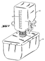
- a valve is shown prior to connection and after connection.
- the valve is provided with a self-sealing valve 10 connected to a first container 12 which is provided with graduations 14, a handle 15 and a tamper evident ring 16.
- the container is, in this example, formed from a plastics material.
- a coupling unit 11 is provided on the uppermost surface of a second container 13.
- the valve 10 is operated by rotating the first container 12 in relation to the coupling unit 11 on the second container 13.
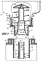
- the valve and the mechanism by which it is opened is now described with reference to Figures 3 to 5.
- the valve has a diameter of approximately 6cm, and the first container neck a diameter of approximately 8cm.
- FIG. 3 shows the valve prior to engagement of the valve 10 with the coupling unit 11.
- the first container 12 and to which the valve 10 is fitted has been inverted.
- the valve 10 comprises a substantially cylindrical main body 17 which is provided with two portions 18,19 which are separated by a shoulder 20.
- a first portion 18 is radially smaller than a second portion 19 and can be inserted into the coupling unit 11.
- a moveable valve member 21 is provided coaxially with the main body 17.
- a number of fins 22 extend radially from the movable valve member 21 and engage in grooves (22a) on the main body 17 in which the valve member 21 slides, opening and closing the valve.
- the valve member 21 is provided with sealing faces 23 at one end and at the opposite end is provided with a cap 24.
- a helical spring 25 is located between the cap 24 and the inner face of the shoulder 20 and is in a partially compressed state. The spring 25 provides the biasing means for urging the valve member 21 to a closed position.
- the first container 12 is provided with a neck 26 having external threads 27 which engage with internal threads 28 located on the inner face of the second portion 19 of the valve body.
- a tamper evident ring 16 is provided at the base of the neck 26 and engages on a serrated section on the first container 12. When the valve 10 is screwed on to the first container 12, the tamper evident ring locates and locks into complementary recessed slots provided on the main body 17 of the valve. If there is relative rotation of the first container 12 to the valve 10, the tamper evident ring 16 is broken and can be easily spotted by an operator.
- a horizontal locating pin 29 is provided proximate to the sealing face end of the valve member 21.
- the coupling unit 11 is provided with a substantially cylindrical main body 30 having, at one end, an overturned lip 31 for abutting against the outer face of the shoulder 20.
- a central tube 32 is provided with a slot 33 having a vertical section 34 and a downwardly cut spiral section 35.
- the coupling unit 11 is provided with a bore 36 extending therethrough for allowing the passage of granular material.
- Figure 4 shows the valve in a partially opened state.
- the valve 10 is engaged with the coupling unit 11 by placing the locating pin 29 in the vertical section 34 of the slot 33.
- the shoulder 20 on the valve 10 abuts against the overturned lip 31 of the coupling unit 11.
- valve member 21 As the first container 12 is rotated, the valve member 21 is forced to move downward as the fins 22 are located in grooves (22a) on the valve body 17. As the valve is turned the locating pin 29 is forced to move along the downwardly cut spiral section 35 of the slot 33. As the locating pin 29 is forced downwardly, the valve member 21 is urged in a downwardly direction and hence a gap 38 opens between the sealing faces 23 and the valve seat 37.
- the degree of opening of the valve 10 and hence the discharge rate of granular material can be precisely regulated by the operator by controlling how far the container is twisted. Further the container 12 can be completely emptied or part emptied of its granular contents.
- Figure 5 shows the valve system when the valve 10 is in a fully opened position and as such the opening 38 is at its maximum extent.
- the valve 10 is closed by rotating the first container 12 in the opposite direction which causes the locating pin 29 to move upwards in the spiral section 35 of the slot 33. With the compression tension of the helical spring 25 urging the valve member 21 in an upwardly direction, the sealing faces 23 cut through the granular flow and seal against the valve seat 37. Any granules that have not been retained in the valve 10 are allowed to fall through the bore 36 of the coupling unit 11.
- the operator can remove the first container 12 and valve 10 from the coupling unit 11. This can only be achieved when the valve is in the fully closed position and hence the locating pin 29 is at the base of the vertical section 34 of the groove 33. This prevents the operator from accidentally separating the first container 12 from the coupling unit 11 while the valve 10 is in an open position. This accordingly reduces the risk of a spillage of the granular material.
Landscapes
- Life Sciences & Earth Sciences (AREA)
- Engineering & Computer Science (AREA)
- Zoology (AREA)
- Insects & Arthropods (AREA)
- Pest Control & Pesticides (AREA)
- Wood Science & Technology (AREA)
- Mechanical Engineering (AREA)
- Environmental Sciences (AREA)
- Closures For Containers (AREA)
- Filling Or Emptying Of Bunkers, Hoppers, And Tanks (AREA)
- Containers And Packaging Bodies Having A Special Means To Remove Contents (AREA)
- Temperature-Responsive Valves (AREA)
- Magnetically Actuated Valves (AREA)
- Electrically Driven Valve-Operating Means (AREA)
Applications Claiming Priority (2)
| Application Number | Priority Date | Filing Date | Title |
|---|---|---|---|
| GB9905948 | 1999-03-15 | ||
| GBGB9905948.7A GB9905948D0 (en) | 1999-03-15 | 1999-03-15 | Valve |
Publications (2)
| Publication Number | Publication Date |
|---|---|
| EP1036497A1 true EP1036497A1 (fr) | 2000-09-20 |
| EP1036497B1 EP1036497B1 (fr) | 2004-01-14 |
Family
ID=10849661
Family Applications (1)
| Application Number | Title | Priority Date | Filing Date |
|---|---|---|---|
| EP00105218A Expired - Lifetime EP1036497B1 (fr) | 1999-03-15 | 2000-03-13 | Soupape |
Country Status (7)
| Country | Link |
|---|---|
| EP (1) | EP1036497B1 (fr) |
| AT (1) | ATE257646T1 (fr) |
| AU (1) | AU743083B2 (fr) |
| CA (1) | CA2300490C (fr) |
| DE (1) | DE60007676T2 (fr) |
| ES (1) | ES2214179T3 (fr) |
| GB (1) | GB9905948D0 (fr) |
Citations (3)
| Publication number | Priority date | Publication date | Assignee | Title |
|---|---|---|---|---|
| US4947986A (en) * | 1988-05-04 | 1990-08-14 | Tecnoma | Apparatus for introducing a metered quantity of product into a vessel |
| EP0389919A1 (fr) | 1989-03-27 | 1990-10-03 | Deere & Company | Dispositif de distribution d'engrais et d'insecticides à écoulement libre ou similaires |
| EP0685155A1 (fr) * | 1994-05-07 | 1995-12-06 | Horstine Farmery Limited | Soupape |
-
1999
- 1999-03-15 GB GBGB9905948.7A patent/GB9905948D0/en not_active Ceased
-
2000
- 2000-02-18 AU AU17589/00A patent/AU743083B2/en not_active Expired
- 2000-03-13 AT AT00105218T patent/ATE257646T1/de not_active IP Right Cessation
- 2000-03-13 DE DE60007676T patent/DE60007676T2/de not_active Expired - Lifetime
- 2000-03-13 ES ES00105218T patent/ES2214179T3/es not_active Expired - Lifetime
- 2000-03-13 CA CA002300490A patent/CA2300490C/fr not_active Expired - Lifetime
- 2000-03-13 EP EP00105218A patent/EP1036497B1/fr not_active Expired - Lifetime
Patent Citations (5)
| Publication number | Priority date | Publication date | Assignee | Title |
|---|---|---|---|---|
| US4947986A (en) * | 1988-05-04 | 1990-08-14 | Tecnoma | Apparatus for introducing a metered quantity of product into a vessel |
| EP0389919A1 (fr) | 1989-03-27 | 1990-10-03 | Deere & Company | Dispositif de distribution d'engrais et d'insecticides à écoulement libre ou similaires |
| EP0498473A2 (fr) | 1989-03-27 | 1992-08-12 | Deere & Company | Méthode de transfert d'un produit chimique granulé |
| EP0498474A2 (fr) | 1989-03-27 | 1992-08-12 | Deere & Company | Elément agricole |
| EP0685155A1 (fr) * | 1994-05-07 | 1995-12-06 | Horstine Farmery Limited | Soupape |
Also Published As
| Publication number | Publication date |
|---|---|
| CA2300490A1 (fr) | 2000-09-15 |
| ES2214179T3 (es) | 2004-09-16 |
| ATE257646T1 (de) | 2004-01-15 |
| CA2300490C (fr) | 2008-05-20 |
| DE60007676T2 (de) | 2004-07-15 |
| GB9905948D0 (en) | 1999-05-05 |
| AU1758900A (en) | 2000-11-16 |
| DE60007676D1 (de) | 2004-02-19 |
| AU743083B2 (en) | 2002-01-17 |
| EP1036497B1 (fr) | 2004-01-14 |
Similar Documents
| Publication | Publication Date | Title |
|---|---|---|
| US6325115B1 (en) | Valve | |
| CA2388539C (fr) | Clapet de distribution de liquide a alimentation par gravite | |
| US6450214B1 (en) | Gravity feed fluid dispensing valve | |
| US7641079B2 (en) | Aerosol can valve and cover assembly | |
| EP1121323B1 (fr) | Couvercle distributeur | |
| US5975164A (en) | Nozzle for dispensing container and receptacle for receiving same | |
| CN101743175A (zh) | 显窃启封盖 | |
| US7017782B2 (en) | Child resistant safety cap for applicator tubes | |
| US5265777A (en) | Push-push tilting dispensing cap system | |
| US6321948B1 (en) | Tap and valve assembly | |
| US6595486B2 (en) | Non-refillable valve | |
| AU658642B2 (en) | A tamper evident vent system for containers | |
| WO2002076846A1 (fr) | Capsule distributrice a soupape a pousser pour contenants | |
| EP1036497B1 (fr) | Soupape | |
| US7204394B2 (en) | Liquid container having gate valve | |
| US6499721B2 (en) | Bulk container valve | |
| US20050127113A1 (en) | Blocking element for use in a valve for a non-refillable pressurized container | |
| JP2023536303A (ja) | アダプタ | |
| CA2091520A1 (fr) | Receptacle a soupape de sortie | |
| US20260035149A1 (en) | Dispensing closure for a container and container with such a dispensing closure | |
| US295708A (en) | August h | |
| WO2006016864A1 (fr) | Dispositif de fermeture pour recipients |
Legal Events
| Date | Code | Title | Description |
|---|---|---|---|
| PUAI | Public reference made under article 153(3) epc to a published international application that has entered the european phase |
Free format text: ORIGINAL CODE: 0009012 |
|
| AK | Designated contracting states |
Kind code of ref document: A1 Designated state(s): AT BE CH CY DE DK ES FI FR GB GR IE IT LI LU MC NL PT SE |
|
| AX | Request for extension of the european patent |
Free format text: AL;LT;LV;MK;RO;SI |
|
| RAP1 | Party data changed (applicant data changed or rights of an application transferred) |
Owner name: SYNGENTA PARTICIPATIONS AG |
|
| 17P | Request for examination filed |
Effective date: 20010219 |
|
| AKX | Designation fees paid |
Free format text: AT BE CH CY DE DK ES FI FR GB GR IE IT LI LU MC NL PT SE |
|
| 17Q | First examination report despatched |
Effective date: 20021217 |
|
| GRAP | Despatch of communication of intention to grant a patent |
Free format text: ORIGINAL CODE: EPIDOSNIGR1 |
|
| GRAS | Grant fee paid |
Free format text: ORIGINAL CODE: EPIDOSNIGR3 |
|
| GRAA | (expected) grant |
Free format text: ORIGINAL CODE: 0009210 |
|
| RIN1 | Information on inventor provided before grant (corrected) |
Inventor name: TULIANI, NICHOLAS DEEPAK Inventor name: COWLAND, JOHN PATRICK |
|
| AK | Designated contracting states |
Kind code of ref document: B1 Designated state(s): AT BE CH CY DE DK ES FI FR GB GR IE IT LI LU MC NL PT SE |
|
| PG25 | Lapsed in a contracting state [announced via postgrant information from national office to epo] |
Ref country code: LI Free format text: LAPSE BECAUSE OF FAILURE TO SUBMIT A TRANSLATION OF THE DESCRIPTION OR TO PAY THE FEE WITHIN THE PRESCRIBED TIME-LIMIT Effective date: 20040114 Ref country code: FI Free format text: LAPSE BECAUSE OF FAILURE TO SUBMIT A TRANSLATION OF THE DESCRIPTION OR TO PAY THE FEE WITHIN THE PRESCRIBED TIME-LIMIT Effective date: 20040114 Ref country code: IT Free format text: LAPSE BECAUSE OF FAILURE TO SUBMIT A TRANSLATION OF THE DESCRIPTION OR TO PAY THE FEE WITHIN THE PRESCRIBED TIME-LIMIT;WARNING: LAPSES OF ITALIAN PATENTS WITH EFFECTIVE DATE BEFORE 2007 MAY HAVE OCCURRED AT ANY TIME BEFORE 2007. THE CORRECT EFFECTIVE DATE MAY BE DIFFERENT FROM THE ONE RECORDED. Effective date: 20040114 Ref country code: CY Free format text: LAPSE BECAUSE OF FAILURE TO SUBMIT A TRANSLATION OF THE DESCRIPTION OR TO PAY THE FEE WITHIN THE PRESCRIBED TIME-LIMIT Effective date: 20040114 Ref country code: AT Free format text: LAPSE BECAUSE OF FAILURE TO SUBMIT A TRANSLATION OF THE DESCRIPTION OR TO PAY THE FEE WITHIN THE PRESCRIBED TIME-LIMIT Effective date: 20040114 Ref country code: CH Free format text: LAPSE BECAUSE OF FAILURE TO SUBMIT A TRANSLATION OF THE DESCRIPTION OR TO PAY THE FEE WITHIN THE PRESCRIBED TIME-LIMIT Effective date: 20040114 |
|
| REG | Reference to a national code |
Ref country code: GB Ref legal event code: FG4D |
|
| REG | Reference to a national code |
Ref country code: CH Ref legal event code: EP |
|
| REG | Reference to a national code |
Ref country code: IE Ref legal event code: FG4D |
|
| REF | Corresponds to: |
Ref document number: 60007676 Country of ref document: DE Date of ref document: 20040219 Kind code of ref document: P |
|
| PG25 | Lapsed in a contracting state [announced via postgrant information from national office to epo] |
Ref country code: LU Free format text: LAPSE BECAUSE OF NON-PAYMENT OF DUE FEES Effective date: 20040313 |
|
| PG25 | Lapsed in a contracting state [announced via postgrant information from national office to epo] |
Ref country code: MC Free format text: LAPSE BECAUSE OF NON-PAYMENT OF DUE FEES Effective date: 20040331 |
|
| PG25 | Lapsed in a contracting state [announced via postgrant information from national office to epo] |
Ref country code: SE Free format text: LAPSE BECAUSE OF FAILURE TO SUBMIT A TRANSLATION OF THE DESCRIPTION OR TO PAY THE FEE WITHIN THE PRESCRIBED TIME-LIMIT Effective date: 20040414 Ref country code: GR Free format text: LAPSE BECAUSE OF FAILURE TO SUBMIT A TRANSLATION OF THE DESCRIPTION OR TO PAY THE FEE WITHIN THE PRESCRIBED TIME-LIMIT Effective date: 20040414 Ref country code: DK Free format text: LAPSE BECAUSE OF FAILURE TO SUBMIT A TRANSLATION OF THE DESCRIPTION OR TO PAY THE FEE WITHIN THE PRESCRIBED TIME-LIMIT Effective date: 20040414 |
|
| REG | Reference to a national code |
Ref country code: CH Ref legal event code: PL |
|
| REG | Reference to a national code |
Ref country code: ES Ref legal event code: FG2A Ref document number: 2214179 Country of ref document: ES Kind code of ref document: T3 |
|
| ET | Fr: translation filed | ||
| PLBE | No opposition filed within time limit |
Free format text: ORIGINAL CODE: 0009261 |
|
| STAA | Information on the status of an ep patent application or granted ep patent |
Free format text: STATUS: NO OPPOSITION FILED WITHIN TIME LIMIT |
|
| 26N | No opposition filed |
Effective date: 20041015 |
|
| PG25 | Lapsed in a contracting state [announced via postgrant information from national office to epo] |
Ref country code: PT Free format text: LAPSE BECAUSE OF NON-PAYMENT OF DUE FEES Effective date: 20040614 |
|
| REG | Reference to a national code |
Ref country code: FR Ref legal event code: PLFP Year of fee payment: 17 |
|
| REG | Reference to a national code |
Ref country code: FR Ref legal event code: PLFP Year of fee payment: 18 |
|
| REG | Reference to a national code |
Ref country code: FR Ref legal event code: PLFP Year of fee payment: 19 |
|
| PGFP | Annual fee paid to national office [announced via postgrant information from national office to epo] |
Ref country code: DE Payment date: 20190215 Year of fee payment: 20 Ref country code: IE Payment date: 20190227 Year of fee payment: 20 Ref country code: GB Payment date: 20190227 Year of fee payment: 20 |
|
| PGFP | Annual fee paid to national office [announced via postgrant information from national office to epo] |
Ref country code: BE Payment date: 20190313 Year of fee payment: 20 Ref country code: NL Payment date: 20190301 Year of fee payment: 20 Ref country code: FR Payment date: 20190220 Year of fee payment: 20 |
|
| PGFP | Annual fee paid to national office [announced via postgrant information from national office to epo] |
Ref country code: ES Payment date: 20190401 Year of fee payment: 20 |
|
| REG | Reference to a national code |
Ref country code: DE Ref legal event code: R071 Ref document number: 60007676 Country of ref document: DE |
|
| REG | Reference to a national code |
Ref country code: NL Ref legal event code: MK Effective date: 20200312 |
|
| REG | Reference to a national code |
Ref country code: GB Ref legal event code: PE20 Expiry date: 20200312 |
|
| REG | Reference to a national code |
Ref country code: BE Ref legal event code: MK Effective date: 20200313 |
|
| REG | Reference to a national code |
Ref country code: IE Ref legal event code: MK9A |
|
| PG25 | Lapsed in a contracting state [announced via postgrant information from national office to epo] |
Ref country code: GB Free format text: LAPSE BECAUSE OF EXPIRATION OF PROTECTION Effective date: 20200312 |
|
| PG25 | Lapsed in a contracting state [announced via postgrant information from national office to epo] |
Ref country code: IE Free format text: LAPSE BECAUSE OF EXPIRATION OF PROTECTION Effective date: 20200313 |
|
| REG | Reference to a national code |
Ref country code: ES Ref legal event code: FD2A Effective date: 20220103 |
|
| PG25 | Lapsed in a contracting state [announced via postgrant information from national office to epo] |
Ref country code: ES Free format text: LAPSE BECAUSE OF EXPIRATION OF PROTECTION Effective date: 20200314 |