EP1036621B1 - Verfahren zum Bruchtrennen eines Bauteiles in zwischen Bauteilbegrenzungen und einer Durchbrechung vorgesehen Querschnitten, insbesondere einer geteilten Lageranordnung - Google Patents
Verfahren zum Bruchtrennen eines Bauteiles in zwischen Bauteilbegrenzungen und einer Durchbrechung vorgesehen Querschnitten, insbesondere einer geteilten Lageranordnung Download PDFInfo
- Publication number
- EP1036621B1 EP1036621B1 EP00103754A EP00103754A EP1036621B1 EP 1036621 B1 EP1036621 B1 EP 1036621B1 EP 00103754 A EP00103754 A EP 00103754A EP 00103754 A EP00103754 A EP 00103754A EP 1036621 B1 EP1036621 B1 EP 1036621B1
- Authority
- EP
- European Patent Office
- Prior art keywords
- component
- breaking
- bearing
- fracturing
- arrangement
- Prior art date
- Legal status (The legal status is an assumption and is not a legal conclusion. Google has not performed a legal analysis and makes no representation as to the accuracy of the status listed.)
- Expired - Lifetime
Links
- 238000000034 method Methods 0.000 title claims description 10
- 230000005489 elastic deformation Effects 0.000 claims description 6
- 230000000977 initiatory effect Effects 0.000 claims description 3
- 238000005452 bending Methods 0.000 claims description 2
- 230000000284 resting effect Effects 0.000 claims description 2
- 230000008719 thickening Effects 0.000 claims 1
- 238000000926 separation method Methods 0.000 description 17
- 238000005266 casting Methods 0.000 description 1
- 238000010276 construction Methods 0.000 description 1
- 230000010354 integration Effects 0.000 description 1
- 238000004519 manufacturing process Methods 0.000 description 1
- 238000005192 partition Methods 0.000 description 1
- 239000003351 stiffener Substances 0.000 description 1
Images
Classifications
-
- B—PERFORMING OPERATIONS; TRANSPORTING
- B23—MACHINE TOOLS; METAL-WORKING NOT OTHERWISE PROVIDED FOR
- B23D—PLANING; SLOTTING; SHEARING; BROACHING; SAWING; FILING; SCRAPING; LIKE OPERATIONS FOR WORKING METAL BY REMOVING MATERIAL, NOT OTHERWISE PROVIDED FOR
- B23D31/00—Shearing machines or shearing devices covered by none or more than one of the groups B23D15/00 - B23D29/00; Combinations of shearing machines
- B23D31/002—Breaking machines, i.e. pre-cutting and subsequent breaking
- B23D31/003—Breaking machines, i.e. pre-cutting and subsequent breaking for rings
-
- F—MECHANICAL ENGINEERING; LIGHTING; HEATING; WEAPONS; BLASTING
- F16—ENGINEERING ELEMENTS AND UNITS; GENERAL MEASURES FOR PRODUCING AND MAINTAINING EFFECTIVE FUNCTIONING OF MACHINES OR INSTALLATIONS; THERMAL INSULATION IN GENERAL
- F16C—SHAFTS; FLEXIBLE SHAFTS; ELEMENTS OR CRANKSHAFT MECHANISMS; ROTARY BODIES OTHER THAN GEARING ELEMENTS; BEARINGS
- F16C9/00—Bearings for crankshafts or connecting-rods; Attachment of connecting-rods
- F16C9/02—Crankshaft bearings
Definitions
- the invention relates to a method for breaking separation of a Component in between component limits and an opening provided cross sections, in particular a split Bearing arrangement, before breaking separation in parts of the Fracture separation cross-sections specifically target the breaking strength of the component reduced by a geometric and / or technological notch is, and also at least on the inner circumference of the opening an element which can be brought into abutment on the component section to be separated a breaking force acting orthogonal to the fracture separating cross-sections is initiated, the component section to be separated by means of outside the opening on the outer contour of the Component section acting forces is supported.
- DE 44 13 255 A1 describes a device for breaking a component known, e.g. two separable, usable in the opening of a component
- Half domes covers the diameter of the opening are chosen to be a predetermined amount smaller. This measure is selected in size so that the component with respect to its deformation when breaking remains in the elastic range, this being controlled in a controlled manner Deformation of the break initiation support in the intended notch points serves.
- the component sections to be separated can be due to different geometric design a different elastic Behavior show with the disadvantage that the actual fracture separating surfaces face each other the desired direction of the fracture dividing angles.
- the invention has for its object to provide a generic method for Break separation of a component with different strengths or elastic Behavior in the component sections to be separated to achieve a flawless Fracture separation without developing the aforementioned disadvantages.
- Supporting forces or external supporting forces is advantageously e.g. a flexible Bearing cover from a stiff bearing bracket of a machine housing flawlessly break separation, avoiding break separation surfaces inclined to the screw axis are and thus damage to the fracture parting surfaces due to shear stresses due to screwing forces. Further is due to the lack of the aforementioned Thrust the round shape of the opening when screwed advantageously ensured, also occurring by repeated screwing There are no signs of settlement.
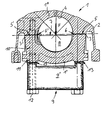
- the invention is based on a bearing arrangement shown as an example in the drawing described in a machine housing of a reciprocating piston machine.
- a bearing arrangement 1 For breaking separation of a bearing arrangement 1 e.g. in a machine housing 2 a not shown piston engine between component limits 3, 3 'and an opening 4 provided cross sections 5, 5' procedurally before breaking separation in parts of the breaking separation cross-sections 5, 5 'the breaking strength of the bearing arrangement 1 specifically by a geometric and / or technological score 6, 6 'reduced.
- the bearing arrangement 1 comprises, for example for a crankshaft after casting the machine housing 2 one Bearing cover 1 ', with a 1 "bearing bracket integrated in the machine housing 2 in one-piece connection. Due to the integral integration of the camp chair 1 "in the machine housing 2 is subject to the bearing chair 1" when the Bearing cover 1 'of this a relatively small elastic deformation. In contrast, is subject to the protruding bearing cap 1 'from the bearing bracket 1' at Fracture separation of a much stronger elastic deformation. Hence result differing elasticity on both sides of the notch points 6 and 6 'when breaking Deformations that cause unfavorable crack guidance when breaking.
- the fracture separation method according to the invention further developed in that with a component section to be separated or bearing cover 1 'of relatively great flexibility, the elastic deformation by outside the opening 4 on the outer contour of the component section or bearing cover 1 'acting supporting forces is limited.
- the arranged according to the invention acting from the outside Supporting forces are achieved in an advantageously simple manner in that the one to be separated Component section or the bearing cover 1 'by means of a detachably arranged Stiffening device 9 is designed to be rigid.
- the stiffening device 9 is preferably designed such that these together with the bearing cover 1 'approximately the bending stiffness of the machine housing 2 remaining camp chairs 1 "corresponds.
- a stiffening device 9 that is simple in construction and easy to handle is further achieved in that a screwable to the bearing assembly 1 Bearing cover 1 'in the screw through holes 10 each have a thread 11 is provided for bolts 12, by means of which the bearing cover 1 'through a detachable arrangement of the stiffening device designed as a rigid flat piece 9 ' 9 resting on the free screw-pipe ends 13 of the bearing cap 1 'is stiffened for breaking separation.
- the one used to introduce external supporting forces into the flexible bearing cover 1 ' bridge-like stiffening device 9 is also advantageous for an automatically controlled production is suitable.
- These stiffeners can also be used 9 for several bearing arrangements 1 to a rigid one with the other Frame connected.
Landscapes
- Engineering & Computer Science (AREA)
- Mechanical Engineering (AREA)
- Shafts, Cranks, Connecting Bars, And Related Bearings (AREA)
- Perforating, Stamping-Out Or Severing By Means Other Than Cutting (AREA)
Description
Claims (3)
- Verfahren zum Bruchtrennen eines Bauteiles in zwischen Bauteilbegrenzungen und einer Durchbrechung vorgesehenen Querschnitten, insbesondere einer geteilten Lageranordnung,dadurch gekennzeichnet,wobei vor dem Bruchtrennen in Teilbereichen der Bruchtrenn-Querschnitt(5,5') die Bruchfestigkeit des Bauteiles (1) gezielt durch eine geometrische und/oder technologische Kerbstelle (6,6') verringert wird, undferner am Innenumfang der Durchbrechung (4) über zumindest ein am abzutrennenden Bauteilabschnitt ( 1') in Anlage bringbares Element (7) eine orthogonal zu den Bruchtrenn-Querschnitten (5,5') wirkende Bruchkraft einwirkt, wobeider abzutrennende Bauteilabschnitt (1') mittels außerhalb der Durchbrechung (4) an der äußeren Kontur des Bauteilabschnittes (1') einwirkende Kräfte gestützt wird,dass die Bruchauslösung mittels einer über die Kontur und/oder Anordnung des Elementes ( 7 bzw. 8) gesteuert vorbestimmten elastischen Verformung des Bauteiles (1) im Bereich der Kerbstellen (6,6') unterstützt wird, wobeidie elastische Verformung des abzutrennenden Bauteilabschnittes (1') mit relativ großer Biegeweichheit durch eine biegesteife Gestaltung des abzutrennenden Bauteilabschnittes (1') mittels einer an diesem Bauteilabschnitt (1') lösbar angeordneten Versteifungseinrichtung (9) begrenzt wird.
- Verfahren nach Anspruch 1, gekennzeichnet durch die Verwendung zum Bruchtrennen eines Lagerdeckels (1') einer Lageranordnung (1) eines Pleuels und/oder eines Maschinengehäuses (2) einer Hubkolbenmaschine.
- Verfahren nach Anspruch 2, dadurch gekennzeichnet,daß bei einem mit der Lageranordnung (1) verschraubbaren Lagerdeckel (1') in dessen Schrauben-Durchgangsbohrungen (10) jeweils ein Gewinde (11) für Schraubbolzen (12) vorgesehen wird, mittels denender Lagerdeckel (1') durch eine lösbare Anordnung der als biegesteifes Flachstück (9') ausgebildeten Versteifungseinrichtung (9) unter Auflage auf den freien Schrauben-Pfeifenenden (13) des Lagerdeckels (1') zum Bruchtrennen versteift wird.
Applications Claiming Priority (2)
| Application Number | Priority Date | Filing Date | Title |
|---|---|---|---|
| DE19911598 | 1999-03-16 | ||
| DE19911598A DE19911598A1 (de) | 1999-03-16 | 1999-03-16 | Verfahren zum Bruchtrennen eines Bauteiles in zwischen Bauteilbegrenzungen und einer Durchbrechung vorgesehenen Querschnitten, insbesondere einer geteilten Lageranordnung |
Publications (2)
| Publication Number | Publication Date |
|---|---|
| EP1036621A1 EP1036621A1 (de) | 2000-09-20 |
| EP1036621B1 true EP1036621B1 (de) | 2003-07-23 |
Family
ID=7901109
Family Applications (1)
| Application Number | Title | Priority Date | Filing Date |
|---|---|---|---|
| EP00103754A Expired - Lifetime EP1036621B1 (de) | 1999-03-16 | 2000-02-23 | Verfahren zum Bruchtrennen eines Bauteiles in zwischen Bauteilbegrenzungen und einer Durchbrechung vorgesehen Querschnitten, insbesondere einer geteilten Lageranordnung |
Country Status (2)
| Country | Link |
|---|---|
| EP (1) | EP1036621B1 (de) |
| DE (2) | DE19911598A1 (de) |
Families Citing this family (1)
| Publication number | Priority date | Publication date | Assignee | Title |
|---|---|---|---|---|
| DE102005011843B4 (de) * | 2005-02-22 | 2010-09-23 | Mauser-Werke Oberndorf Maschinenbau Gmbh | Verfahren zum Bruchtrennen und Crackeinheit |
Citations (2)
| Publication number | Priority date | Publication date | Assignee | Title |
|---|---|---|---|---|
| EP0985479A1 (de) * | 1998-08-30 | 2000-03-15 | Isuzu Motors Limited | Verfahren und Vorrichtung zum Brechen einer Pleuelstange |
| EP1002609A1 (de) * | 1998-11-19 | 2000-05-24 | Bayerische Motoren Werke Aktiengesellschaft | Vorrichtung zum Bruchtrennen eines drehgesichert gehaltenen Lagerdeckels von einer Lageranordnung eines Bauteils, insbesondere Antriebsstrang-Bauteil für Kfz |
Family Cites Families (3)
| Publication number | Priority date | Publication date | Assignee | Title |
|---|---|---|---|---|
| DE4037429A1 (de) * | 1990-11-14 | 1992-05-21 | Ex Cell O Gmbh | Bearbeitungsverfahren- und anlage fuer ein lagerauge aufweisende maschinenteile |
| DE4316354C2 (de) * | 1993-05-15 | 1996-07-18 | Grob Gmbh & Co Kg | Verfahren und Vorrichtung zum Bruchtrennen von Pleueln |
| DE69517965T2 (de) * | 1994-03-25 | 2001-03-01 | Tri-Way Machine Ltd., Sterling Heights | Verfahren und vorrichtung zum bruchtrennen von pleueln und dergleichen |
-
1999
- 1999-03-16 DE DE19911598A patent/DE19911598A1/de not_active Withdrawn
-
2000
- 2000-02-23 EP EP00103754A patent/EP1036621B1/de not_active Expired - Lifetime
- 2000-02-23 DE DE50002954T patent/DE50002954D1/de not_active Expired - Lifetime
Patent Citations (2)
| Publication number | Priority date | Publication date | Assignee | Title |
|---|---|---|---|---|
| EP0985479A1 (de) * | 1998-08-30 | 2000-03-15 | Isuzu Motors Limited | Verfahren und Vorrichtung zum Brechen einer Pleuelstange |
| EP1002609A1 (de) * | 1998-11-19 | 2000-05-24 | Bayerische Motoren Werke Aktiengesellschaft | Vorrichtung zum Bruchtrennen eines drehgesichert gehaltenen Lagerdeckels von einer Lageranordnung eines Bauteils, insbesondere Antriebsstrang-Bauteil für Kfz |
Also Published As
| Publication number | Publication date |
|---|---|
| DE19911598A1 (de) | 2000-09-21 |
| EP1036621A1 (de) | 2000-09-20 |
| DE50002954D1 (de) | 2003-08-28 |
Similar Documents
| Publication | Publication Date | Title |
|---|---|---|
| EP1121520B1 (de) | Kolben für einen verbrennungsmotor | |
| DE202008017862U1 (de) | Verstärkte Energieabsorptionsvorrichtung und -anordnung | |
| EP3096014B1 (de) | Exzenterschneckenpumpe | |
| DE3122533A1 (de) | Brennkraftmaschine | |
| DE6929793U (de) | Lenkvorrichtung | |
| DE102021103668B3 (de) | Anordnung zum Einpressen eines Lagers | |
| DE602004005989T2 (de) | Hubschrauberrotor mit einem Schwingungsdämpfer | |
| WO2000055869A1 (de) | Überspannungsableiter mit wenigstens einem zugelement | |
| DE102009028458A1 (de) | Modulares Lenkerelement | |
| DE102016224670A1 (de) | Lageranordnung zur Lagerung eines Schraubenkompressorrotors und Verfahren zur Montage eines Schraubenkompressors | |
| EP3983689B1 (de) | Schwenkwiegenlagerung und verfahren zur herstellung einer schwenkwiegenlagerung | |
| DE602005005136T2 (de) | Verbindung zwischen Kolbenstange und Querspritzkopf einer hin- und hergehenden Maschine | |
| DE69517779T2 (de) | Elastische Kupplung für drehende Wellen | |
| EP1036621A1 (de) | Verfahren zum Bruchtrennen eines Bauteiles in zwischen Bauteilbegrenzungen und einer Durchbrechung vorgesehen Querschnitten, insbesondere einer geteilten Lageranordnung | |
| WO2019096609A1 (de) | KOLBEN MIT ZWEI UNTERSCHIEDLICH GROßEN NABENBOHRUNGEN | |
| DE112008000928T5 (de) | Verfahren zur Montage eines Kältemaschinenkompressors | |
| EP1795754B1 (de) | Universalflansch | |
| DE3800355A1 (de) | Kompressor | |
| EP2505838B1 (de) | Kolbenverdichter | |
| EP1715200B1 (de) | Kugelgelenkverbindung | |
| DE19725381A1 (de) | Beschlag zum Befestigen an Platten oder dergleichen, insbesondere Glasscheiben | |
| EP1839790B1 (de) | Vorrichtung und Verfahren zum Bruchtrennen von Pleueln | |
| EP2528796B1 (de) | Trägerplatte mit schraubbefestigung | |
| DE202005005872U1 (de) | Stützhülse für Zylinderkopfschrauben und Zylinderkopf | |
| DE102005011843B4 (de) | Verfahren zum Bruchtrennen und Crackeinheit |
Legal Events
| Date | Code | Title | Description |
|---|---|---|---|
| PUAI | Public reference made under article 153(3) epc to a published international application that has entered the european phase |
Free format text: ORIGINAL CODE: 0009012 |
|
| AK | Designated contracting states |
Kind code of ref document: A1 Designated state(s): DE FR GB IT |
|
| AX | Request for extension of the european patent |
Free format text: AL;LT;LV;MK;RO;SI |
|
| 17P | Request for examination filed |
Effective date: 20010301 |
|
| AKX | Designation fees paid |
Free format text: DE FR GB IT |
|
| 17Q | First examination report despatched |
Effective date: 20020524 |
|
| GRAH | Despatch of communication of intention to grant a patent |
Free format text: ORIGINAL CODE: EPIDOS IGRA |
|
| GRAH | Despatch of communication of intention to grant a patent |
Free format text: ORIGINAL CODE: EPIDOS IGRA |
|
| GRAA | (expected) grant |
Free format text: ORIGINAL CODE: 0009210 |
|
| AK | Designated contracting states |
Designated state(s): DE FR GB IT |
|
| REG | Reference to a national code |
Ref country code: GB Ref legal event code: FG4D Free format text: NOT ENGLISH |
|
| GBT | Gb: translation of ep patent filed (gb section 77(6)(a)/1977) |
Effective date: 20030723 |
|
| REF | Corresponds to: |
Ref document number: 50002954 Country of ref document: DE Date of ref document: 20030828 Kind code of ref document: P |
|
| ET | Fr: translation filed | ||
| PLBE | No opposition filed within time limit |
Free format text: ORIGINAL CODE: 0009261 |
|
| STAA | Information on the status of an ep patent application or granted ep patent |
Free format text: STATUS: NO OPPOSITION FILED WITHIN TIME LIMIT |
|
| 26N | No opposition filed |
Effective date: 20040426 |
|
| REG | Reference to a national code |
Ref country code: FR Ref legal event code: PLFP Year of fee payment: 17 |
|
| REG | Reference to a national code |
Ref country code: FR Ref legal event code: PLFP Year of fee payment: 18 |
|
| PGFP | Annual fee paid to national office [announced via postgrant information from national office to epo] |
Ref country code: DE Payment date: 20170216 Year of fee payment: 18 Ref country code: FR Payment date: 20170220 Year of fee payment: 18 |
|
| PGFP | Annual fee paid to national office [announced via postgrant information from national office to epo] |
Ref country code: GB Payment date: 20170221 Year of fee payment: 18 |
|
| PGFP | Annual fee paid to national office [announced via postgrant information from national office to epo] |
Ref country code: IT Payment date: 20170217 Year of fee payment: 18 |
|
| REG | Reference to a national code |
Ref country code: DE Ref legal event code: R119 Ref document number: 50002954 Country of ref document: DE |
|
| GBPC | Gb: european patent ceased through non-payment of renewal fee |
Effective date: 20180223 |
|
| REG | Reference to a national code |
Ref country code: FR Ref legal event code: ST Effective date: 20181031 |
|
| PG25 | Lapsed in a contracting state [announced via postgrant information from national office to epo] |
Ref country code: DE Free format text: LAPSE BECAUSE OF NON-PAYMENT OF DUE FEES Effective date: 20180901 |
|
| PG25 | Lapsed in a contracting state [announced via postgrant information from national office to epo] |
Ref country code: IT Free format text: LAPSE BECAUSE OF NON-PAYMENT OF DUE FEES Effective date: 20180223 Ref country code: FR Free format text: LAPSE BECAUSE OF NON-PAYMENT OF DUE FEES Effective date: 20180228 Ref country code: GB Free format text: LAPSE BECAUSE OF NON-PAYMENT OF DUE FEES Effective date: 20180223 |