EP1036894B1 - Déversoir de secours - Google Patents
Déversoir de secours Download PDFInfo
- Publication number
- EP1036894B1 EP1036894B1 EP00105250A EP00105250A EP1036894B1 EP 1036894 B1 EP1036894 B1 EP 1036894B1 EP 00105250 A EP00105250 A EP 00105250A EP 00105250 A EP00105250 A EP 00105250A EP 1036894 B1 EP1036894 B1 EP 1036894B1
- Authority
- EP
- European Patent Office
- Prior art keywords
- arrangement according
- water
- emergency
- height
- inlet opening
- Prior art date
- Legal status (The legal status is an assumption and is not a legal conclusion. Google has not performed a legal analysis and makes no representation as to the accuracy of the status listed.)
- Expired - Lifetime
Links
Images




Classifications
-
- E—FIXED CONSTRUCTIONS
- E04—BUILDING
- E04D—ROOF COVERINGS; SKY-LIGHTS; GUTTERS; ROOF-WORKING TOOLS
- E04D13/00—Special arrangements or devices in connection with roof coverings; Protection against birds; Roof drainage ; Sky-lights
- E04D13/04—Roof drainage; Drainage fittings in flat roofs, balconies or the like
- E04D13/0404—Drainage on the roof surface
- E04D13/0409—Drainage outlets, e.g. gullies
- E04D13/0431—Drainage outlets, e.g. gullies with horizontal evacuation over the border of the roof
-
- E—FIXED CONSTRUCTIONS
- E04—BUILDING
- E04D—ROOF COVERINGS; SKY-LIGHTS; GUTTERS; ROOF-WORKING TOOLS
- E04D13/00—Special arrangements or devices in connection with roof coverings; Protection against birds; Roof drainage ; Sky-lights
- E04D13/04—Roof drainage; Drainage fittings in flat roofs, balconies or the like
- E04D13/0404—Drainage on the roof surface
- E04D13/0409—Drainage outlets, e.g. gullies
-
- E—FIXED CONSTRUCTIONS
- E04—BUILDING
- E04D—ROOF COVERINGS; SKY-LIGHTS; GUTTERS; ROOF-WORKING TOOLS
- E04D13/00—Special arrangements or devices in connection with roof coverings; Protection against birds; Roof drainage ; Sky-lights
- E04D13/04—Roof drainage; Drainage fittings in flat roofs, balconies or the like
- E04D13/0404—Drainage on the roof surface
- E04D13/0409—Drainage outlets, e.g. gullies
- E04D2013/0422—Drainage outlets, e.g. gullies for draining water above the roof level, e.g. gullies with overflow ports
-
- E—FIXED CONSTRUCTIONS
- E04—BUILDING
- E04D—ROOF COVERINGS; SKY-LIGHTS; GUTTERS; ROOF-WORKING TOOLS
- E04D13/00—Special arrangements or devices in connection with roof coverings; Protection against birds; Roof drainage ; Sky-lights
- E04D13/04—Roof drainage; Drainage fittings in flat roofs, balconies or the like
- E04D13/0404—Drainage on the roof surface
- E04D13/0409—Drainage outlets, e.g. gullies
- E04D2013/0427—Drainage outlets, e.g. gullies with means for controlling the flow in the outlet
Definitions
- the invention relates to an emergency drain device for a Water drains with drained area, especially flat roof a drain opening with a water level limit value to the area-determining accumulation device and with a vertical connected to the drain opening Drain pipe.
- water drains that drain with drain holes in of the surface.
- the water drains can do this are located freely in the surface, that is to say, flow from all sides be, or the surface formed on lateral boundaries be, for example, as a parapet drain of a flat roof.
- the Leakage capacity of the water drains is dimensioned so that a certain water retention level should not be exceeded. If the water drains do not provide the required drainage capacity, the water accumulation level on the surface can increase, causing not only impaired the possible accessibility of the area can cause significant static problems can be, namely if the surface on a supporting substructure is mounted, such as for flat roofs and Cover areas on ships is the case.
- the reduction of the expiry date The normal water drainage can be caused by constipation the water drainage system of the water drains or else the drainage openings of the water drains or any upstream ones Grid caused.
- the emergency drain device dimensioned so that after reaching the water accumulation limit there is no significant additional accumulation height.
- the emergency drain device must therefore be as sudden as possible provide a high drainage rate. From constructive and For architectural reasons, this high drainage rate should be a matter of course if possible not through over-sized drain openings and drain pipes can be achieved.
- the invention is therefore based on the problem, a To design the emergency drain device of the type mentioned at the beginning that a sudden high drainage rate with normal diameters for the drain opening and the vertical Drain pipe is achieved.
- a container in the flow direction of the drain opening is connected upstream, which has a side wall that up to to a height that is less than the height of the side wall, has at least one inlet opening and above the inlet opening with an airtight lid Forms space.
- the emergency drain device is based on the effect that the inlet opening when the water accumulation limit value is exceeded in the side wall of the container due to the accumulated Water is sealed airtight, so that the filling of the vertical drain pipe in the container above the Inlet opening forms a negative pressure, which is reinforced Sucking the water from the surface into the container - and with it into the vertical drain pipe - causes.
- This effect occurs if the inlet opening is only a little above the height of the water accumulation limit value, so that the vacuum effect mentioned quickly when the water accumulation limit is reached "starts" and for an abruptly high water drainage performance that is much higher than a conventional one Gravity flow.
- the inlet opening can lead to the inlet opening until something extends beyond the level of the water retention limit.
- the height of the inlet opening should be the water accumulation limit usually by no more than about 1 cm.
- the inlet opening extends into the or extends below the level of the water retention limit.
- the inlet opening this will expediently be the other hand extend to the bottom of the side wall of the container.
- the inlet opening can expediently at the same time the function of an inlet grille to protect against gravel, leaves and similar contaminants when formed from a variety is formed by slots.
- the slots are convenient directed vertically.
- the container can be used to facilitate attachment of the container be completed with a floor that is immediately on the Area, or with a preferably corresponding to the accumulation height Distance to the surface can be mountable.
- the inlet opening is funnel-shaped, preferably a has radially outwardly bent edge to the horizontal.
- the accumulation device is expediently passed through the mouth opening a pipe section formed, which is preferably immediate opens into the vertical drain pipe.
- a pipe section formed which is preferably immediate opens into the vertical drain pipe.
- connection to the vertical drain pipe via a horizontal one Line for example a horizontal manifold to manufacture for several drain openings of the emergency drain device.
- the damming device then as a kind of weir inside or outside of the container. Is the emergency drain facility arranged at an edge delimiting the surface, a horizontal drain pipe can be passed through the edge and a damming device forming over the surface have uplifting level.
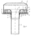
- FIG. 1 shows a vertical section through an inventive Emergency drain device that is sealed by a sealed surface 1 a flat roof is passed through.
- This is a vertical one Drain pipe 2 with a widened as a sleeve 3 upper end sealed used in area 1 of the flat roof.
- a pipe section 4 which by a at the edge of the sleeve 3 inserted annular seal 5 sealed is connected to the drain pipe 2.
- the seal relates focus on both watertightness and a certain amount Gas leaks.
- the pipe section 4 forms a drain opening 6.
- the pipe section 4 is flared at the upper end, by an upper edge 7 of the pipe section radially outwards is bent so that the edge 7 points to the horizontal, that is in parallel and with a water retention limit H corresponding Distance to surface 1 is.
- the drain opening 6 thus formed, which can flow from all sides is surrounded by a container 8, which has a cylindrical side wall 9, an airtight lid wall 10 and has a bottom 11 surrounding the tube section 4 in a ring shape.
- the container 8 which is circular in cross section, has such a diameter that the side wall 9 a clear distance to the free end of the bent edge 7 of the Pipe section 4 has.
- the bottom 11 is provided with through openings 12 through which projecting fastening bolts 13 anchored in the surface 1, on the one nut 14 for fastening the container is screwed onto the surface 1.
- the side wall 9 has an inlet opening 15 through a plurality of uniformly on the circumference of the side wall 9 spaced vertical slots 16 is formed.
- the vertical slots 16 extend at their lower end to the bottom 11 and at its upper end to the level of in the horizontal bent edge 7 of the pipe section 4.
- the height of the inlet opening selected in this exemplary embodiment 15 corresponds to the water accumulation limit value H at which the emergency drain device should take effect and via which the pent-up Water must not rise significantly to avoid static Risk of overloading.
- Edge 7 is arranged somewhat higher than the upper edge of the inlet opening 15.
- the water accumulating on the roof surface 1 provides for a rise in the water level within the container 8. This also applies because of the principle of the communicating tubes then when the water level over the height of the slots 16 of the Inlet opening 15 rises. Is that due to the height of the drain opening 6 certain water accumulation limit value H is reached the container 8 with airtight security, because the vertical slots 16 of the inlet opening 15 filled with water are.
- the water accumulation limit value H arises in this embodiment by a within the Container 8 provided, circumferential cylindrical wall 17th Only when the water level on the sealed surface 1 is the height of the cylindrical wall 17, there may be a filling of the vertical drain pipe 2 and to form the vacuum effect in the closed above the inlet openings 15 Container 8 come.
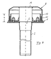
- the illustrated embodiment has above the drain opening 6 two in the axis of the vertical Drain pipe 2 crossing guide walls 18, which a vortex formation counteract above the drain opening 6.
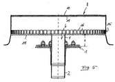
- the bottom 11 of the container 8 in the amount of the limit accumulation value H above the sealed surface 1 and has the pipe section centrally 4, which is inserted into the vertical drain pipe.
- the inlet opening is distributed over the circumference of the side wall 9 15 forming vertical slots 16 distributed here have a much lower height than in the in the Figures 1 to 4 shown containers 8.
- the total cross section required the inlet opening 15 is reached here that the diameter of the container 8 is much larger than in the embodiments according to Figures 1 to 4.
- the diameter of the housing 8 is more than in this embodiment five times the diameter of the vertical drain pipe 2 or the drain opening 6, while the diameter of the in Figures 1 to 4 shown housing 8 only about three times as large is like the diameter of the drain opening 6.
- the cover wall 10 be provided with an acoustic insulation layer 19, such as this is shown in Figure 5.
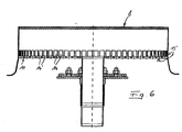
- FIG. 6 illustrates that the bottom 11 of the container 8 can be provided with openings 16 ' either alone or together with vertical slots 16 the Form inlet opening 15 of the container 8.
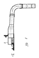
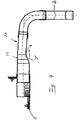
- FIGS. 7 to 9 show exemplary embodiments of an emergency drain device, which is arranged on an edge 20, so that a the surface 1 continuing horizontal drain pipe 21 through the vertically standing edge 20 is passed.
- the drain opening In this case, 6 is vertical and is located in a pipe section 4, which is initially to be carried out by the edge 20 has a rectangular cross section and with a Transition piece 22 merges into a round cross section. about a bend 23 is the connection to the vertical drain pipe 2 manufactured.
- the closed pipe section 4 is closed rectangular container 8, the three of which do not face the edge 20 showing walls with the vertical slots 16 for formation the inlet opening 15 is equipped.
- a box 7 'acting as a weir the height of the water accumulation limit value H which is therefore used as an accumulation device acts.
- An outlet via the horizontal outlet pipe 21 can therefore only take place when that on the surface 1 Water reaches or exceeds the water accumulation limit value H. Has.
- Figure 10 shows an embodiment of an emergency drain device with a horizontal drain pipe 21, in which the water accumulation limit H again through a raised container 8 in one of the exemplary embodiments according to FIGS. 5 and 6 Shape is determined.
- the inlet opening 15 is here - how in the embodiment of Figure 6 - by small vertical Slots 16 and openings 16 'in the bottom 11 of the container 8 educated.
- a wall 24 in front of the cross section of the horizontal Drain pipe 21 ensures that only after the water accumulation limit value is exceeded H water into the horizontal drain pipe 21 can occur.
- Figure 11 illustrates that the housing 8 is not rectangular must be, but in the illustrated embodiment has a semicircular contour in plan view.
- the emergency drain device ensures a through the negative pressure effect of sudden discharge of large Amounts of water so that when the water retention limit is exceeded another significant rise in the water level on the surface 1 can be prevented by more than 1 or 2 cm is.
Landscapes
- Architecture (AREA)
- Civil Engineering (AREA)
- Structural Engineering (AREA)
- Engineering & Computer Science (AREA)
- Structure Of Emergency Protection For Nuclear Reactors (AREA)
- Sink And Installation For Waste Water (AREA)
- Electrical Discharge Machining, Electrochemical Machining, And Combined Machining (AREA)
- Cyclones (AREA)
- Alarm Systems (AREA)
- Liquid Developers In Electrophotography (AREA)
- Transplanting Machines (AREA)
- Liquid Crystal Substances (AREA)
- Pressure Vessels And Lids Thereof (AREA)
Claims (13)
- Déversoir de secours pour une surface (1) drainée par des écoulements d'eau, en particulier un toit plat, comprenant une ouverture d'écoulement (6), un agencement d'accumulation (7) déterminant le niveau d'une limite (H) d'accumulation d'eau par rapport à la surface (1), et un tuyau d'écoulement vertical (2) qui est en liaison avec l'ouverture d'écoulement (6), caractérisé en ce qu'un récipient (8) est installé avant l'ouverture d'écoulement (6) dans la direction d'écoulement et présente une paroi latérale (9) qui comporte jusqu'à un niveau inférieur à la hauteur de la paroi latérale (9), au moins une ouverture d'entrée (15) et forme au-dessus de l'ouverture d'entrée (15), avec une paroi de couvercle (10), une chambre fermée de façon étanche à l'air par l'eau accumulée.
- Déversoir de secours selon la revendication 1, caractérisé en ce que l'ouverture d'entrée (15) s'étend jusque dans la zone du niveau de l'agencement d'accumulation (7).
- Déversoir de secours selon la revendication 2, caractérisé en ce que l'ouverture d'entrée (15) s'étend jusqu'au niveau de l'agencement d'accumulation (7) ou en-dessous de ce niveau.
- Déversoir de secours selon l'une des revendications 1 à 3, caractérisé en ce que l'ouverture d'entrée (15) s'étend d'autre part jusqu'au bord inférieur de la paroi latérale (9).
- Déversoir de secours selon l'une des revendications 1 à 4, caractérisé en ce que l'ouverture d'entrée (15) est constituée par de multiples fentes (16).
- Déversoir de secours selon la revendication 5, caractérisé en ce que les fentes (16) sont orientées verticalement.
- Déversoir de secours selon l'une des revendications 1 à 6, caractérisé en ce que le récipient (8) est fermé par un fond (11) vers la surface plane.
- Déversoir de secours selon l'une des revendications 1 à 7, caractérisé en ce que l'agencement d'accumulation (7) est constitué par le bord d'une pièce tubulaire (4).
- Déversoir de secours selon la revendication 8, caractérisé en ce que la pièce tubulaire (4) débouche directement dans le tube d'écoulement vertical (2).
- Déversoir de secours selon la revendication 7 ou 8, caractérisé en ce que le bord (7) de l'ouverture d'écoulement (6) est élargi en forme d'entonnoir.
- Déversoir de secours selon la revendication 10, caractérisé en ce que l'ouverture d'écoulement (6) présente un bord recourbé radialement jusqu'à l'horizontale.
- Déversoir de secours selon l'une des revendications 1 à 11, caractérisé en ce que l'agencement d'écoulement (7', 7") se trouve à l'extérieur du récipient (8).
- Déversoir de secours selon la revendication 12, caractérisé en ce que l'agencement d'accumulation est constitué sous la forme d'un gradin (7") s'élevant au-dessus de la surface (1) en avant ou dans un tuyau d'écoulement horizontal (21) qui se continue par le tuyau d'écoulement vertical (2).
Applications Claiming Priority (2)
| Application Number | Priority Date | Filing Date | Title |
|---|---|---|---|
| DE19912012A DE19912012C2 (de) | 1999-03-17 | 1999-03-17 | Notablaufvorrichtung |
| DE19912012 | 1999-03-17 |
Publications (3)
| Publication Number | Publication Date |
|---|---|
| EP1036894A2 EP1036894A2 (fr) | 2000-09-20 |
| EP1036894A3 EP1036894A3 (fr) | 2001-01-03 |
| EP1036894B1 true EP1036894B1 (fr) | 2004-05-06 |
Family
ID=7901383
Family Applications (1)
| Application Number | Title | Priority Date | Filing Date |
|---|---|---|---|
| EP00105250A Expired - Lifetime EP1036894B1 (fr) | 1999-03-17 | 2000-03-14 | Déversoir de secours |
Country Status (4)
| Country | Link |
|---|---|
| EP (1) | EP1036894B1 (fr) |
| AT (1) | ATE266132T1 (fr) |
| DE (3) | DE19912012C2 (fr) |
| DK (1) | DK1036894T3 (fr) |
Cited By (1)
| Publication number | Priority date | Publication date | Assignee | Title |
|---|---|---|---|---|
| EP2034104A2 (fr) | 2007-09-07 | 2009-03-11 | Wolfgang Dipl.-Ing. Vahlbrauk | Décharge d'urgence destinée au drainage d'une surface |
Families Citing this family (8)
| Publication number | Priority date | Publication date | Assignee | Title |
|---|---|---|---|---|
| DE19860160C2 (de) * | 1998-12-24 | 2001-03-08 | Wolfgang Vahlbrauk | Wasserablauf |
| DE10104530A1 (de) * | 2001-01-31 | 2002-08-14 | Sita Bauelemente | Vorrichtung zur Entwässerung von Flachdächern mit einem Randabschluss |
| EP1544371A1 (fr) | 2003-12-16 | 2005-06-22 | Geberit Technik Ag | Bouche d'évacuation d'eau pour toiture |
| DE102004024904A1 (de) * | 2004-05-19 | 2005-12-15 | Wavin B.V. | Wasserablauf für versiegelte ebene Flächen |
| DE202006003103U1 (de) * | 2006-02-27 | 2006-04-27 | B/S/T Gmbh Koch Kunststofftechnologie | Notüberlauf |
| IT1395999B1 (it) * | 2009-03-10 | 2012-11-09 | Valsir Spa | Pozzetto di scarico d'acqua, in particolare per sistemi ad effetto sifonico di drenaggio dei tetti |
| DE102009023463B4 (de) * | 2009-06-02 | 2016-04-07 | Wolfgang Vahlbrauk | Einrichtung zur Entwässerung einer Dachfläche |
| BE1019400A3 (nl) | 2010-07-06 | 2012-06-05 | Aquadraat Engineering Bvba | Verbeterde dakkolk voor hemelwaterafvoer in onderdruk en nieuw gebruik ervan in uv-hemelwaterafvoersysteem. |
Family Cites Families (11)
| Publication number | Priority date | Publication date | Assignee | Title |
|---|---|---|---|---|
| FR675691A (fr) * | 1929-05-24 | 1930-02-13 | Dispositif d'évacuation des eaux pour toitures-terrasses recouvertes d'un produit plastique étanche | |
| US2701644A (en) * | 1952-03-07 | 1955-02-08 | Edgar J Griffiths | Filter with medium supported by suction piping |
| DE1942084U (de) * | 1966-03-17 | 1966-07-07 | Herbert Dipl Ing Zettel | Regenablaufverzoegerungsrohr zur flachdachentwaesserung. |
| DE1806527C3 (de) * | 1968-11-02 | 1978-12-21 | Josam Manufacturing Co., Michigan City, Ind. (V.St.A.) | Flachdachablauf |
| FI52612C (fi) * | 1975-12-30 | 1977-10-10 | Kontekla Oy | Rakennuksen kattokaivo tai sentapainen. |
| FI53235C (fr) * | 1976-06-09 | 1978-03-10 | Kontekla Oy | |
| GB2285460B (en) * | 1993-12-14 | 1997-01-08 | Harmer Holdings Ltd | Syphonic rainwater outlet |
| US5615526A (en) * | 1995-05-08 | 1997-04-01 | Palmer; Dale W. | Drains for single layer synthetic roofing and waterproofing membranes |
| DE29611847U1 (de) * | 1996-07-06 | 1996-09-12 | AKO Rohre Systeme Technologien GmbH & Co. Kommanditgesellschaft, 50667 Köln | Dachentwässerungsvorrichtung |
| DE19852561C1 (de) * | 1998-11-13 | 2000-07-06 | Harzmann Optima Marketing Und | Wasserabflußsystem für Dachflächen |
| DE29905122U1 (de) * | 1999-03-22 | 2000-08-10 | Vahlbrauk, Wolfgang, Dipl.-Ing., 37581 Bad Gandersheim | Vorrichtung zur Ableitung von Wasser |
-
1999
- 1999-03-17 DE DE19912012A patent/DE19912012C2/de not_active Expired - Fee Related
- 1999-05-03 DE DE29907721U patent/DE29907721U1/de not_active Expired - Lifetime
-
2000
- 2000-03-14 DK DK00105250T patent/DK1036894T3/da active
- 2000-03-14 EP EP00105250A patent/EP1036894B1/fr not_active Expired - Lifetime
- 2000-03-14 DE DE50006297T patent/DE50006297D1/de not_active Expired - Lifetime
- 2000-03-14 AT AT00105250T patent/ATE266132T1/de active
Cited By (2)
| Publication number | Priority date | Publication date | Assignee | Title |
|---|---|---|---|---|
| EP2034104A2 (fr) | 2007-09-07 | 2009-03-11 | Wolfgang Dipl.-Ing. Vahlbrauk | Décharge d'urgence destinée au drainage d'une surface |
| DE102007042527A1 (de) | 2007-09-07 | 2009-03-26 | Vahlbrauk, Wolfgang, Dipl.-Ing. | Notablauf zur Entwässerung einer Fläche |
Also Published As
| Publication number | Publication date |
|---|---|
| ATE266132T1 (de) | 2004-05-15 |
| DE19912012C2 (de) | 2003-02-06 |
| DE29907721U1 (de) | 1999-07-22 |
| EP1036894A2 (fr) | 2000-09-20 |
| EP1036894A3 (fr) | 2001-01-03 |
| DK1036894T3 (da) | 2004-06-07 |
| DE50006297D1 (de) | 2004-06-09 |
| DE19912012A1 (de) | 2000-10-19 |
Similar Documents
| Publication | Publication Date | Title |
|---|---|---|
| EP1334250B1 (fr) | Dispositif pour evacuer l'eau des toits plats, des balcons, des terrasses ou d'autres constructions plates | |
| DE69702971T2 (de) | Vorrichtung zum abführen des regenwassers von dächern | |
| EP0963918A1 (fr) | Citerne d'eau | |
| EP1036894A2 (fr) | Déversoir de secours | |
| DE102005012439B4 (de) | Wasserabführvorrichtung | |
| DE69621095T2 (de) | Unterirdischer Pufferbehälter zum Lagern und Behandeln von Regenwasser | |
| DE19812398C2 (de) | Verfahren und Vorrichtung zur Ableitung von Wasser von einer im wesentlichen ebenen Fläche | |
| EP2034104B1 (fr) | Décharge d'urgence destinée au drainage d'une surface | |
| DE602004007445T2 (de) | Bodenablauf | |
| DE60019999T2 (de) | Vorrichtung zum Abführen des Regenwassers mit reguliertem Durchfluss | |
| DE10360310A1 (de) | Ablaufvorrichtung | |
| EP1826334B1 (fr) | Déversoir de secours | |
| DE10201347A1 (de) | Einlaufvorrichtung für die Abführung von Regenwasser von einem Dach | |
| DE4334747C2 (de) | Abwasserschacht | |
| DE19721624C2 (de) | Dachentwässerungsvorrichtung | |
| DE3002511A1 (de) | Oelabscheider | |
| DE202014011094U1 (de) | Filtersubstratrinnenelement | |
| EP1167645B1 (fr) | Dispositif d'entrée dans le sol | |
| DE19960128C2 (de) | Wasserablauf für versiegelte Flächen | |
| DE2650253A1 (de) | Gully- oder bodenabflussfang | |
| DE19956024C2 (de) | Ablaufvorrichtung | |
| DE102005012438B4 (de) | Wasserabführvorrichtung | |
| DE2829585A1 (de) | Vorrichtung an einem regenwasserfallrohr fuer dachrinnen zum ableiten des regenwassers vom fallrohr | |
| DE29821255U1 (de) | Vorrichtung zur Ableitung von Wasser von einer im wesentlichen ebenen Fläche | |
| DE102024105893A1 (de) | Gebäudeanordnung und Regulierungseinheit zur Verwendung in einer Gebäudeanordnung |
Legal Events
| Date | Code | Title | Description |
|---|---|---|---|
| PUAI | Public reference made under article 153(3) epc to a published international application that has entered the european phase |
Free format text: ORIGINAL CODE: 0009012 |
|
| AK | Designated contracting states |
Kind code of ref document: A2 Designated state(s): AT DE DK FI FR GB |
|
| AX | Request for extension of the european patent |
Free format text: AL;LT;LV;MK;RO;SI |
|
| PUAL | Search report despatched |
Free format text: ORIGINAL CODE: 0009013 |
|
| AK | Designated contracting states |
Kind code of ref document: A3 Designated state(s): AT BE CH CY DE DK ES FI FR GB GR IE IT LI LU MC NL PT SE |
|
| AX | Request for extension of the european patent |
Free format text: AL;LT;LV;MK;RO;SI |
|
| 17P | Request for examination filed |
Effective date: 20010117 |
|
| AKX | Designation fees paid |
Free format text: AT DE DK FI FR GB |
|
| 17Q | First examination report despatched |
Effective date: 20021015 |
|
| GRAP | Despatch of communication of intention to grant a patent |
Free format text: ORIGINAL CODE: EPIDOSNIGR1 |
|
| GRAS | Grant fee paid |
Free format text: ORIGINAL CODE: EPIDOSNIGR3 |
|
| GRAA | (expected) grant |
Free format text: ORIGINAL CODE: 0009210 |
|
| AK | Designated contracting states |
Kind code of ref document: B1 Designated state(s): AT DE DK FI FR GB |
|
| PG25 | Lapsed in a contracting state [announced via postgrant information from national office to epo] |
Ref country code: FR Free format text: LAPSE BECAUSE OF FAILURE TO SUBMIT A TRANSLATION OF THE DESCRIPTION OR TO PAY THE FEE WITHIN THE PRESCRIBED TIME-LIMIT Effective date: 20040506 |
|
| REG | Reference to a national code |
Ref country code: GB Ref legal event code: FG4D Free format text: NOT ENGLISH |
|
| REG | Reference to a national code |
Ref country code: DK Ref legal event code: T3 |
|
| REF | Corresponds to: |
Ref document number: 50006297 Country of ref document: DE Date of ref document: 20040609 Kind code of ref document: P |
|
| GBT | Gb: translation of ep patent filed (gb section 77(6)(a)/1977) |
Effective date: 20040616 |
|
| PLBE | No opposition filed within time limit |
Free format text: ORIGINAL CODE: 0009261 |
|
| STAA | Information on the status of an ep patent application or granted ep patent |
Free format text: STATUS: NO OPPOSITION FILED WITHIN TIME LIMIT |
|
| EN | Fr: translation not filed | ||
| 26N | No opposition filed |
Effective date: 20050208 |
|
| REG | Reference to a national code |
Ref country code: DE Ref legal event code: R082 Ref document number: 50006297 Country of ref document: DE Representative=s name: GRAMM, LINS & PARTNER PATENT- UND RECHTSANWAEL, DE |
|
| PGFP | Annual fee paid to national office [announced via postgrant information from national office to epo] |
Ref country code: DK Payment date: 20160322 Year of fee payment: 17 |
|
| PGFP | Annual fee paid to national office [announced via postgrant information from national office to epo] |
Ref country code: FI Payment date: 20160318 Year of fee payment: 17 Ref country code: GB Payment date: 20160322 Year of fee payment: 17 Ref country code: AT Payment date: 20160318 Year of fee payment: 17 |
|
| REG | Reference to a national code |
Ref country code: DK Ref legal event code: EBP Effective date: 20170331 |
|
| PG25 | Lapsed in a contracting state [announced via postgrant information from national office to epo] |
Ref country code: FI Free format text: LAPSE BECAUSE OF NON-PAYMENT OF DUE FEES Effective date: 20170314 |
|
| REG | Reference to a national code |
Ref country code: AT Ref legal event code: MM01 Ref document number: 266132 Country of ref document: AT Kind code of ref document: T Effective date: 20170314 |
|
| GBPC | Gb: european patent ceased through non-payment of renewal fee |
Effective date: 20170314 |
|
| PG25 | Lapsed in a contracting state [announced via postgrant information from national office to epo] |
Ref country code: AT Free format text: LAPSE BECAUSE OF NON-PAYMENT OF DUE FEES Effective date: 20170314 |
|
| PG25 | Lapsed in a contracting state [announced via postgrant information from national office to epo] |
Ref country code: GB Free format text: LAPSE BECAUSE OF NON-PAYMENT OF DUE FEES Effective date: 20170314 |
|
| PG25 | Lapsed in a contracting state [announced via postgrant information from national office to epo] |
Ref country code: DK Free format text: LAPSE BECAUSE OF NON-PAYMENT OF DUE FEES Effective date: 20170331 |
|
| PGFP | Annual fee paid to national office [announced via postgrant information from national office to epo] |
Ref country code: DE Payment date: 20190327 Year of fee payment: 20 |
|
| REG | Reference to a national code |
Ref country code: DE Ref legal event code: R071 Ref document number: 50006297 Country of ref document: DE |