EP1036942A2 - Steueranordnung für einen Arbeitszylinder - Google Patents
Steueranordnung für einen Arbeitszylinder Download PDFInfo
- Publication number
- EP1036942A2 EP1036942A2 EP00890022A EP00890022A EP1036942A2 EP 1036942 A2 EP1036942 A2 EP 1036942A2 EP 00890022 A EP00890022 A EP 00890022A EP 00890022 A EP00890022 A EP 00890022A EP 1036942 A2 EP1036942 A2 EP 1036942A2
- Authority
- EP
- European Patent Office
- Prior art keywords
- control
- adjusting
- pressure medium
- cylinder
- pressure
- Prior art date
- Legal status (The legal status is an assumption and is not a legal conclusion. Google has not performed a legal analysis and makes no representation as to the accuracy of the status listed.)
- Granted
Links
- 230000036316 preload Effects 0.000 claims description 4
- 238000007789 sealing Methods 0.000 claims description 3
- 230000001105 regulatory effect Effects 0.000 abstract description 3
- 238000012423 maintenance Methods 0.000 description 5
- 230000008878 coupling Effects 0.000 description 3
- 238000010168 coupling process Methods 0.000 description 3
- 238000005859 coupling reaction Methods 0.000 description 3
- 230000006837 decompression Effects 0.000 description 3
- 230000035939 shock Effects 0.000 description 3
- 230000001276 controlling effect Effects 0.000 description 2
- 230000000694 effects Effects 0.000 description 2
- 238000004519 manufacturing process Methods 0.000 description 2
- 230000004308 accommodation Effects 0.000 description 1
- 230000004913 activation Effects 0.000 description 1
- 230000005540 biological transmission Effects 0.000 description 1
- 238000010276 construction Methods 0.000 description 1
- 238000010586 diagram Methods 0.000 description 1
- 238000005516 engineering process Methods 0.000 description 1
- 230000007257 malfunction Effects 0.000 description 1
- 230000035945 sensitivity Effects 0.000 description 1
- 238000009423 ventilation Methods 0.000 description 1
Images


Classifications
-
- F—MECHANICAL ENGINEERING; LIGHTING; HEATING; WEAPONS; BLASTING
- F15—FLUID-PRESSURE ACTUATORS; HYDRAULICS OR PNEUMATICS IN GENERAL
- F15B—SYSTEMS ACTING BY MEANS OF FLUIDS IN GENERAL; FLUID-PRESSURE ACTUATORS, e.g. SERVOMOTORS; DETAILS OF FLUID-PRESSURE SYSTEMS, NOT OTHERWISE PROVIDED FOR
- F15B13/00—Details of servomotor systems ; Valves for servomotor systems
- F15B13/02—Fluid distribution or supply devices characterised by their adaptation to the control of servomotors
- F15B13/04—Fluid distribution or supply devices characterised by their adaptation to the control of servomotors for use with a single servomotor
- F15B13/0401—Valve members; Fluid interconnections therefor
- F15B13/0402—Valve members; Fluid interconnections therefor for linearly sliding valves, e.g. spool valves
-
- Y—GENERAL TAGGING OF NEW TECHNOLOGICAL DEVELOPMENTS; GENERAL TAGGING OF CROSS-SECTIONAL TECHNOLOGIES SPANNING OVER SEVERAL SECTIONS OF THE IPC; TECHNICAL SUBJECTS COVERED BY FORMER USPC CROSS-REFERENCE ART COLLECTIONS [XRACs] AND DIGESTS
- Y10—TECHNICAL SUBJECTS COVERED BY FORMER USPC
- Y10S—TECHNICAL SUBJECTS COVERED BY FORMER USPC CROSS-REFERENCE ART COLLECTIONS [XRACs] AND DIGESTS
- Y10S251/00—Valves and valve actuation
- Y10S251/90—Valves with o-rings
-
- Y—GENERAL TAGGING OF NEW TECHNOLOGICAL DEVELOPMENTS; GENERAL TAGGING OF CROSS-SECTIONAL TECHNOLOGIES SPANNING OVER SEVERAL SECTIONS OF THE IPC; TECHNICAL SUBJECTS COVERED BY FORMER USPC CROSS-REFERENCE ART COLLECTIONS [XRACs] AND DIGESTS
- Y10—TECHNICAL SUBJECTS COVERED BY FORMER USPC
- Y10T—TECHNICAL SUBJECTS COVERED BY FORMER US CLASSIFICATION
- Y10T137/00—Fluid handling
- Y10T137/8593—Systems
- Y10T137/87096—Valves with separate, correlated, actuators
-
- Y—GENERAL TAGGING OF NEW TECHNOLOGICAL DEVELOPMENTS; GENERAL TAGGING OF CROSS-SECTIONAL TECHNOLOGIES SPANNING OVER SEVERAL SECTIONS OF THE IPC; TECHNICAL SUBJECTS COVERED BY FORMER USPC CROSS-REFERENCE ART COLLECTIONS [XRACs] AND DIGESTS
- Y10—TECHNICAL SUBJECTS COVERED BY FORMER USPC
- Y10T—TECHNICAL SUBJECTS COVERED BY FORMER US CLASSIFICATION
- Y10T137/00—Fluid handling
- Y10T137/8593—Systems
- Y10T137/87169—Supply and exhaust
- Y10T137/87217—Motor
Definitions
- the invention relates to a control arrangement for a pressure fluid-operated Working cylinder, with two separately adjustable, each with a pressure medium source and a pressure medium discharge on the one hand and the Working cylinders on the other hand connected control valves for the two Cylinder sides.
- 4/3-way valves (servo or proportional valves) are usually used with which the leading to the two cylinder sides Consumer connections, the pressure medium connection and the tank or pressure medium discharge connection be controlled together.
- the one for control required four control edges are in a rigid relation on one common adjusting element, for example a piston-type control slide, which ensures in a simple manner that, for example, when pressure is applied the other cylinder side corresponding to one cylinder side is vented or connected to the tank.
- a similar control arrangement is also, for example, from EP 654 608 B1 known in connection with pneumatic cylinders without piston rods, where the separate control option on both cylinder sides to enable this a more efficient braking of the piston or for it possible increase in the adjustment speed is used.
- the object of the present invention is to provide a control arrangement for the to improve the type mentioned so that the disadvantages of known designs are avoided and that in particular the effort in Reduced with regard to components to be assembled and connected individually and thus an easier accommodation of the tax arrangement and a simplification assembly and maintenance.
- the required connecting lines and Connections are arranged in or on the common valve housing, which means assembly and maintenance naturally simplified and error or failure options reduced.
- a corresponding arrangement of the connections on the valve housing provided that the new control arrangement can also be very simple, for example instead of the arrangement mentioned at the beginning with a 4/3 control valve existing applications are used - it is only precaution for the separate actuation of the two adjustment gears in the common valve housing hold true.
- the two Adjusting elements designed as adjusting pistons, coaxial in the valve housing arranged, and over, on the outer end faces opposite each other, separate control drives are adjustable. This results in a constructive simple design of the valve housing and easy accessibility the two separate control drives, which also includes assembly and maintenance improved or simplified.
- each adjusting piston can Invention arranged in a valve housing, preferably for both Adjusting piston common, control bushing, what the separate Production of these cooperating with the control edges of the adjusting pistons Socket made of, for example, extra hardened material or also allows easy replacement of this socket when worn.
- the outer frontal spaces on the control drives through axial holes in the adjusting piston with each other and via a preload valve with the pressure medium drain are connected.
- the outer ones are Rooms on the control drives are often connected directly to the tank connection or via a throttle with the pressure connection and a second throttle with the Tank connection.
- the former has the disadvantage of poor ventilation of the Actuators facing frontal spaces and the occurrence of pressure peaks which can lead to instabilities in the scheme, while the second mentioned training with large throttle cross sections additional power losses occur and with small throttle cross sections the risk of Blockage of the throttle and thus an uncontrolled pressure build-up in it There is room to destroy the usually not to the maximum Regulating drives that can withstand operating pressure. With the above Design according to the invention, these disadvantages are avoided and constant Press in the front rooms on the control drives without additional Loss of performance ensured.
- Embodiment of the invention according to which the control bush between the is opened, preferably divided, two adjustment pistons, the biasing valve than from the outside in the radial direction biased elastic Sealing ring over the opening, preferably over the ends of the two control socket parts, is executed.
- a common for example as a spring-loaded ball valve
- Executed preload valve in a pressure medium drainage or tank Providing leading connecting line can be described with this Design together with an open or split control socket structurally simple execution can be realized, which achieved this almost constant pressure level in the rooms at the control drives to one high control stability without additional leakage losses.
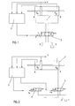
- Fig. 1 and 2 show schematic circuit diagrams of control arrangements for Working cylinders actuatable by pressure medium according to the state described at the beginning the technology and Figures 3 and 4 each show different versions of Control arrangements according to the present invention in a partial longitudinal section.
- a pressure medium actuated cylinder 1 in a conventional manner by means of a 4/3-way valve 2, which on the one hand via ports A and B to the two working spaces of the working cylinder 1 and on the other hand via port P with a pressure medium source and port T with a pressure medium discharge line to the tank is controlled.
- the on the one hand spring-biased control valve 2 is, on the other hand, actuated, for example, by an electromagnet, the voltage supply of this electromagnet, indicated by u, being carried out by a control unit 3 which is supplied with input signals corresponding to the pressures p A and p B and the piston travel x corresponding sensor signals.
- Control arrangement enables control due to the rigid coupling of the pressure medium both sides of the cylinder essentially only exactly the same Operation of the two cylinder rooms - when one is pressurized The other side is inevitably relieved to port T and vice versa. This results in the disadvantages already mentioned at the beginning for example with regard to insufficient load rigidity, pressure surge sensitivity and the same. Other problems can arise with this control arrangement e.g. also occur when the piston rod of the working cylinder 1, contrary to the illustration in FIG. 1, only led out on one side and in this (or other) way there is a significant difference in the volumes to be exchanged occur on both sides of the piston.
- the 4/3-way valve 2 from FIG. 1 that is common to both cylinder sides is now replaced by two independently adjustable (actuation u A and u B ) 3/3-way valves 4, 5, which is very simple and effective way the possibility of independent pressurization or locking and relief of the two cylinder spaces, which, for example, to increase the load rigidity or to improve the positioning accuracy and smoothness at different loads and speeds or to reduce the negative effects of volume differences and can also be used by pressure surges and decompression shocks.
- the two are now separately adjustable, each with the pressure medium source P and the pressure medium drain T on the one hand and the working cylinder (via A and B) on the other connected control valves 4, 5 designed so that their adjusting elements 4 ', 5' are housed in a common valve housing 31, which furthermore the pressure medium connections to be controlled for both cylinder sides and those with the control edges 17, 18 on the one hand and 21, 22 on the other hand, on the adjusting members 4 ', 5' cooperating, control rooms connecting connecting lines.
- the two adjusting members 4 ', 5' are designed as adjusting pistons, arranged coaxially in the valve housing 31 and over on the outer end faces opposite, separate control drives 6, 7 adjustable.
- everyone Adjusting piston 4 ', 5' is arranged in a valve housing 31, here control bushing (32, 33) divided between the two adjusting pistons 4 ', 5' performed what a simple design and manufacture of the valve housing 31st enables.
- the outer end spaces 34, 35 on control drives 6, 7 are with each other and through axial bores 10, 11 in the control piston 4 ', 5' via a centrally arranged preload valve 36 with the pressure medium discharge line T connected.
- This biasing valve 36 is radial from the outside Direction of prestressed elastic sealing ring 15 over the ends of the two Control socket parts 32, 33 realized.
- the two control drives 6, 7 are, for example, electrical Proportional magnets trained and act with appropriate electrical Activation via anchor extensions 36, 37 and adjusting screws 38 on the Adjusting piston 4 ', 5' - springs 8 act in the other direction of movement, 9 which are on the one hand on the control socket parts 32, 33 and on the other supported on transmission sleeves 39, by means of which the anchor extensions 36, 37 can be pushed back with the adjustment pistons 4 ', 5'.
- FIG. 3 It is easy to see that the overall arrangement of FIG. 3 is very small and compact in construction and essentially conventional in terms of connections 1 corresponds - it is only a second Actuator required to perform all functions as described in FIG. 2 to be able to realize.
- the pressure port P of the directional control valve according to FIG. 3 is through the bypass channel 12 divided in the valve housing 31 and to the pressure connection 13 of the Control socket part 32 or the pressure connection 14 of the control socket part 33 guided.
- Via the control edges 17 and 18 on the adjusting piston 4 'and Radial breakthroughs 19 on the control bushing 32 is the consumer space 20 (Port A) connectable to the pressure port 13 or the tank port 16.
- In the currentless basic position of the proportional magnet shown in the Actuator 6 is consumer connection 20 (A) with tank connection 16 connected.
- the control piston 4 'follows shifted to the right whereby the connection of the consumer connection 20 (A) closed to the tank port 16 and the connection from the pressure port 13 to Consumer connection 20 (A) is established.
- connection B connectable to the pressure connection 14 or the tank connection.
- control bushing 40 is now for FIG. 3 both adjusting pistons 4 ', 5' carried out together and undivided and from the right forth in the common valve housing 1 used.
- the pressure medium connections are changed compared to the embodiment of FIG. 3 insofar as here now the connection of the pressure medium source P in the middle and the connections for pressure medium discharge T are provided on the outside.
- the control function of the Arrangement or the possibility of separate control of the two consumer connections A, B remains unchanged compared to FIG. 3.
- the front-side anchor spaces 34, 35 are again in the middle Bores 10, 11 in the adjusting piston 4 ', 5' connected, but now one spring-loaded ball valve as a bias valve 36 in a connection of the right armature space 35 is used for pressure medium discharge T. On too in this way it can advantageously be ensured that it is in rooms 34 and 35 not to uncontrolled pressure build-up and corresponding malfunctions or damage can occur.
Landscapes
- Engineering & Computer Science (AREA)
- Physics & Mathematics (AREA)
- Fluid Mechanics (AREA)
- Mechanical Engineering (AREA)
- General Engineering & Computer Science (AREA)
- Fluid-Pressure Circuits (AREA)
- Valve Housings (AREA)
- Multiple-Way Valves (AREA)
- Actuator (AREA)
- Fluid-Driven Valves (AREA)
- Lifting Devices For Agricultural Implements (AREA)
- Working Measures On Existing Buildindgs (AREA)
Abstract
Description
Claims (5)
- Steueranordnung für einen druckmittelbetätigbaren Arbeitszylinder (1), mit zwei separat verstellbaren, jeweils mit einer Druckmittelquelle (P) und einer Druckmittelableitung (T) einerseits und dem Arbeitszylinder (1) andererseits verbundenen Regelventilen (4, 5) für die beiden Zylinderseiten (A, B), dadurch gekennzeichnet, daß die Verstellorgane (4', 5') der beiden Regelventile (4, 5) in einem gemeinsamen Ventilgehäuse (31) untergebracht sind, welches weiters auch die zu steuernden Druckmittelanschlüsse (A, B, P, T) für beide Zylinderseiten und die diese mit den, mit den Steuerkanten (17, 18; 21, 22) an den Verstellorganen (4', 5') zusammenwirkenden, Steuerräumen verbindenden Verbindungsleitungen aufweist.
- Steueranordnung nach Anspruch 1, dadurch gekennzeichnet, daß die beiden Verstellorgane (4', 5') als Verstellkolben ausgebildet, koaxial im Ventilgehäuse (31) angeordnet, und über an den äußeren Stirnseiten einander gegenüberliegende, separate Regelantriebe (6, 7) verstellbar sind.
- Steueranordnung nach Anspruch 2, dadurch gekennzeichnet, daß jeder Verstellkolben (4', 5') in einer im Ventilgehäuse (31) angeordneten, vorzugsweise für beide Verstellkolben (4', 5') gemeinsamen, Steuerbuchse (32, 33; 40) geführt ist.
- Steueranordnung nach Anspruch 2 oder 3, dadurch gekennzeichnet, daß die äußeren stirnseitigen Räume (34, 35) an den Regelantrieben (6, 7) durch axiale Bohrungen (10, 11) in den Verstellkolben (4', 5') miteinander und über ein Vorspannventil (36) mit der Druckmittelableitung (T) verbunden sind.
- Steueranordnung nach Anspruch 3 und 4, dadurch gekennzeichnet, daß die Steuerbuchse (32, 33) zwischen den beiden Verstellkolben (4', 5') geöffnet, vorzugsweise geteilt, ist, wobei das Vorspannventil (36) als von außen in radialer Richtung vorgespannter elastischer Dichtring (15) über der Öffnung, vorzugsweise über den Enden der beiden Steuerbuchsenteile (32, 33), ausgeführt ist.
Applications Claiming Priority (2)
| Application Number | Priority Date | Filing Date | Title |
|---|---|---|---|
| AT18899U | 1999-03-18 | ||
| AT0018899U AT3017U3 (de) | 1999-03-18 | 1999-03-18 | Steueranordnung für einen arbeitszylinder |
Publications (3)
| Publication Number | Publication Date |
|---|---|
| EP1036942A2 true EP1036942A2 (de) | 2000-09-20 |
| EP1036942A3 EP1036942A3 (de) | 2003-02-12 |
| EP1036942B1 EP1036942B1 (de) | 2004-09-01 |
Family
ID=3483825
Family Applications (1)
| Application Number | Title | Priority Date | Filing Date |
|---|---|---|---|
| EP00890022A Expired - Lifetime EP1036942B1 (de) | 1999-03-18 | 2000-01-26 | Steueranordnung für einen Arbeitszylinder |
Country Status (5)
| Country | Link |
|---|---|
| US (1) | US6561221B1 (de) |
| EP (1) | EP1036942B1 (de) |
| JP (1) | JP4616959B2 (de) |
| AT (1) | AT3017U3 (de) |
| DE (1) | DE50007579D1 (de) |
Cited By (1)
| Publication number | Priority date | Publication date | Assignee | Title |
|---|---|---|---|---|
| EP3771505A3 (de) * | 2019-08-01 | 2021-03-03 | Atlas Copco IAS GmbH | Verfahren zur steuerung eines mechanischen füge- oder umformprozesses |
Families Citing this family (6)
| Publication number | Priority date | Publication date | Assignee | Title |
|---|---|---|---|---|
| DE10041386B4 (de) * | 2000-08-23 | 2008-08-21 | Daimler Ag | System zur Wirkungsgradoptimierung einer Ölversorgung |
| DE102010009975A1 (de) * | 2010-03-03 | 2011-09-08 | Sauer-Danfoss Gmbh & Co Ohg | Verstellvorrichtung für Axialkolbenmaschinen |
| US9897228B2 (en) * | 2015-11-06 | 2018-02-20 | Caterpillar Inc. | Valve having opposing right-angle actuators |
| JP6815103B2 (ja) * | 2016-06-10 | 2021-01-20 | 川崎重工業株式会社 | 流量制御弁装置 |
| EP3545221B1 (de) * | 2016-11-22 | 2025-09-17 | Parker-Hannifin Corporation | Extrem verschleppungsarmes magnetventil |
| DE112020000106T5 (de) * | 2019-11-13 | 2021-07-15 | Langfang Golden Time Technology Development Co., Ltd. | Pumpenventilmodul und dessen Betriebsverfahren, Magnetventil-basiertesPumpenventilmodul zur Bereitstellung einer Massagefunktion für einen Fahrzeugsitz,sowie Fahrzeugsitz |
Family Cites Families (29)
| Publication number | Priority date | Publication date | Assignee | Title |
|---|---|---|---|---|
| US2404349A (en) * | 1944-11-29 | 1946-07-23 | Adel Prec Products Corp | Valve |
| US2619121A (en) * | 1947-10-01 | 1952-11-25 | Denison Eng Co | Solenoid operated valve |
| US2600746A (en) * | 1948-08-30 | 1952-06-17 | Thompson Grinder Co | Fluid pressure control valve |
| US3060969A (en) * | 1960-02-24 | 1962-10-30 | Alkon Products Corp | Hydraulic valve |
| US3254675A (en) * | 1963-11-19 | 1966-06-07 | Johnson Clarence | Multi-purpose solenoid-pilot valve assembly |
| US3618690A (en) * | 1969-05-20 | 1971-11-09 | Caterpillar Tractor Co | Damping and air-purging means for relief valve |
| US4220174A (en) * | 1978-03-29 | 1980-09-02 | Spitz Russell W | Fluid control valves |
| JPS5936151B2 (ja) * | 1978-12-13 | 1984-09-01 | 株式会社昭空 | 切換弁 |
| US4422475A (en) * | 1981-05-29 | 1983-12-27 | Vickers, Incorporated | Variable gain servo controlled directional valve |
| US4456434A (en) * | 1982-03-01 | 1984-06-26 | Vickers, Incorporated | Power transmission |
| US4457341A (en) * | 1982-03-04 | 1984-07-03 | Vickers, Incorporated | Variable pressure drop proportional motor controlled hydraulic directional valve |
| DE3218527A1 (de) * | 1982-05-17 | 1983-11-17 | Kurt 4970 Bad Oeynhausen Varlemann | Selbststeuerndes hydraulisches umschalt-ventil fuer einen doppelwirkenden arbeitszylinder |
| US4565219A (en) * | 1982-09-13 | 1986-01-21 | The Oilgear Japan Company | Multiple-position solenoid-operated control valve |
| EP0114470B1 (de) * | 1982-12-13 | 1986-08-13 | Vickers Incorporated | Zweistufiges hydraulisches Ventil |
| DE3346235A1 (de) * | 1982-12-27 | 1984-07-05 | Nippon Pneumatic Mfg | Steuergeraet fuer hydraulische zylinder |
| DE3406570A1 (de) * | 1984-02-23 | 1985-09-12 | Mannesmann Rexroth GmbH, 8770 Lohr | Elektromagnet/ventil-anordnung |
| DE3406794A1 (de) * | 1984-02-24 | 1985-09-05 | Mannesmann Rexroth GmbH, 8770 Lohr | Druckregelventil |
| US4754780A (en) * | 1987-02-10 | 1988-07-05 | Smith Iii Robert E | Pressure balanced hydraulic coupling |
| DE3708248A1 (de) * | 1987-03-13 | 1988-09-22 | Herion Werke Kg | Wegeventil |
| JPS6469878A (en) * | 1987-09-10 | 1989-03-15 | Diesel Kiki Co | Solenoid proportional pressure control valve |
| US5284220A (en) * | 1988-07-25 | 1994-02-08 | Atsugi Unisia Corporation | Pressure control valve assembly for hydraulic circuit and automotive rear wheel steering system utilizing the same |
| DE3900949A1 (de) * | 1989-01-14 | 1990-07-19 | Bw Hydraulik Gmbh | Elektrohydraulische steuerung zum steuern eines hydraulischen antriebes |
| GB9211898D0 (en) * | 1992-06-05 | 1992-07-15 | Vickers Systems Ltd | Two-stage hydraulic valves |
| DE4307990A1 (de) * | 1993-03-13 | 1994-09-15 | Bosch Gmbh Robert | Hydraulisches Steuerventil |
| LU88379A1 (fr) * | 1993-07-12 | 1994-04-01 | Luxembourg Patent Co | clapet pour un robinet d'une bouteille de gaz comprimé ou liquéfié et robinet pourvu d'un tel clapet |
| DE4339444A1 (de) | 1993-11-19 | 1995-05-24 | Hygrama Ag | Verfahren zum Steuern der Bewegung eines Druckmittelzylinders und Druckmittelzylinder |
| DE4400760C2 (de) * | 1994-01-13 | 1997-03-27 | Festo Kg | Mehrwegeventil |
| DE4416285A1 (de) * | 1994-05-07 | 1995-11-09 | Bosch Gmbh Robert | Elektropneumatische Ventileinrichtung |
| JPH09100922A (ja) * | 1995-10-03 | 1997-04-15 | Nippon Pisuko:Kk | 制御バルブ |
-
1999
- 1999-03-18 AT AT0018899U patent/AT3017U3/de not_active IP Right Cessation
-
2000
- 2000-01-26 EP EP00890022A patent/EP1036942B1/de not_active Expired - Lifetime
- 2000-01-26 DE DE50007579T patent/DE50007579D1/de not_active Expired - Lifetime
- 2000-03-15 US US09/525,915 patent/US6561221B1/en not_active Expired - Fee Related
- 2000-03-21 JP JP2000078937A patent/JP4616959B2/ja not_active Expired - Fee Related
Non-Patent Citations (1)
| Title |
|---|
| None |
Cited By (2)
| Publication number | Priority date | Publication date | Assignee | Title |
|---|---|---|---|---|
| EP3771505A3 (de) * | 2019-08-01 | 2021-03-03 | Atlas Copco IAS GmbH | Verfahren zur steuerung eines mechanischen füge- oder umformprozesses |
| US11772218B2 (en) | 2019-08-01 | 2023-10-03 | Atlas Copco Ias Gmbh | Method for controlling a mechanical joining or forming process |
Also Published As
| Publication number | Publication date |
|---|---|
| DE50007579D1 (de) | 2004-10-07 |
| AT3017U3 (de) | 2000-03-27 |
| AT3017U2 (de) | 1999-08-25 |
| EP1036942A3 (de) | 2003-02-12 |
| EP1036942B1 (de) | 2004-09-01 |
| JP2000297801A (ja) | 2000-10-24 |
| US6561221B1 (en) | 2003-05-13 |
| JP4616959B2 (ja) | 2011-01-19 |
Similar Documents
| Publication | Publication Date | Title |
|---|---|---|
| DE19842029B4 (de) | Verstellung von hydrostatischen Axialkolbenmaschinen mittels Schrittmotor | |
| EP0620371B1 (de) | Hydrauliksystem zur Versorgung offener oder geschlossener Hydraulikfunktionen | |
| EP1370773A1 (de) | Wegeventil | |
| DE102020211288A1 (de) | Hydraulisches Antriebssystem | |
| EP1036942B1 (de) | Steueranordnung für einen Arbeitszylinder | |
| DE10343016B4 (de) | Hydraulisches Steuer- und Stellsystem mit Volumenausgleich | |
| EP1249619B1 (de) | Ventileinheit mit entsperrbarem Rückschlagventil und damit ausgestatteter fluidbetätigter Antrieb | |
| EP1504191B1 (de) | Verstellvorrichtung für hydrostatische kolbenmaschinen | |
| DE3446134A1 (de) | Reversierbare hydraulische maschine | |
| DE3436946A1 (de) | Linearantrieb | |
| EP2813728B1 (de) | Kolbenschieberventil | |
| DE102020109134A1 (de) | Axialkolbenmaschine | |
| EP0717817B1 (de) | Hydraulischer steuerventilblock | |
| DE4340283A1 (de) | Hydraulisches Steuerventil | |
| EP0238782B1 (de) | 5/3-Wege-Ventileinheit | |
| DE102022201755A1 (de) | Steuerschieber mit definiert gebrochener Kreisringkante | |
| DE4020325C2 (de) | Regeleinrichtung für verstellbare Hydropumpen | |
| DE102008012143B4 (de) | Proportionalzylinder sowie zugehöriges Baukastensystem | |
| DE102017107719A1 (de) | Hydraulikventil zum Einstellen eines Hydraulikflüssigkeitsstroms eines Pleuels für eine Brennkraftmaschine mit variabler Verdichtung | |
| DE10330738B4 (de) | Elektrohydraulische Stelleinrichtung | |
| DE102013206975A1 (de) | Hydraulische Steuervorrichtung mit einseitiger Schieberansteuerung | |
| DE19757157C2 (de) | Hydraulischer Linearantrieb | |
| EP0074496B1 (de) | Ventilvorrichtung, insbesondere für Druckgiessmaschinen | |
| DE102021207837A1 (de) | Verfahren zum Betrieb einer Hydromaschine mit Kompensation einer Strömungskraft am Steuerschieber | |
| DE3502506A1 (de) | Ventilfernpositionierungseinrichtung |
Legal Events
| Date | Code | Title | Description |
|---|---|---|---|
| PUAI | Public reference made under article 153(3) epc to a published international application that has entered the european phase |
Free format text: ORIGINAL CODE: 0009012 |
|
| AK | Designated contracting states |
Kind code of ref document: A2 Designated state(s): AT BE CH CY DE DK ES FI FR GB GR IE IT LI LU MC NL PT SE |
|
| AX | Request for extension of the european patent |
Free format text: AL;LT;LV;MK;RO;SI |
|
| PUAL | Search report despatched |
Free format text: ORIGINAL CODE: 0009013 |
|
| AK | Designated contracting states |
Designated state(s): AT BE CH CY DE DK ES FI FR GB GR IE IT LI LU MC NL PT SE |
|
| AX | Request for extension of the european patent |
Extension state: AL LT LV MK RO SI |
|
| 17P | Request for examination filed |
Effective date: 20030409 |
|
| 17Q | First examination report despatched |
Effective date: 20030828 |
|
| AKX | Designation fees paid |
Designated state(s): DE FR GB IT NL |
|
| GRAP | Despatch of communication of intention to grant a patent |
Free format text: ORIGINAL CODE: EPIDOSNIGR1 |
|
| GRAS | Grant fee paid |
Free format text: ORIGINAL CODE: EPIDOSNIGR3 |
|
| GRAA | (expected) grant |
Free format text: ORIGINAL CODE: 0009210 |
|
| AK | Designated contracting states |
Kind code of ref document: B1 Designated state(s): DE FR GB IT NL |
|
| REG | Reference to a national code |
Ref country code: GB Ref legal event code: FG4D Free format text: NOT ENGLISH |
|
| REG | Reference to a national code |
Ref country code: IE Ref legal event code: FG4D Free format text: GERMAN |
|
| REF | Corresponds to: |
Ref document number: 50007579 Country of ref document: DE Date of ref document: 20041007 Kind code of ref document: P |
|
| GBT | Gb: translation of ep patent filed (gb section 77(6)(a)/1977) |
Effective date: 20040916 |
|
| PG25 | Lapsed in a contracting state [announced via postgrant information from national office to epo] |
Ref country code: GB Free format text: LAPSE BECAUSE OF NON-PAYMENT OF DUE FEES Effective date: 20050126 |
|
| REG | Reference to a national code |
Ref country code: IE Ref legal event code: FD4D |
|
| PLBE | No opposition filed within time limit |
Free format text: ORIGINAL CODE: 0009261 |
|
| STAA | Information on the status of an ep patent application or granted ep patent |
Free format text: STATUS: NO OPPOSITION FILED WITHIN TIME LIMIT |
|
| ET | Fr: translation filed | ||
| PG25 | Lapsed in a contracting state [announced via postgrant information from national office to epo] |
Ref country code: NL Free format text: LAPSE BECAUSE OF NON-PAYMENT OF DUE FEES Effective date: 20050801 |
|
| 26N | No opposition filed |
Effective date: 20050602 |
|
| GBPC | Gb: european patent ceased through non-payment of renewal fee |
Effective date: 20050126 |
|
| NLV4 | Nl: lapsed or anulled due to non-payment of the annual fee |
Effective date: 20050801 |
|
| PGFP | Annual fee paid to national office [announced via postgrant information from national office to epo] |
Ref country code: DE Payment date: 20140328 Year of fee payment: 15 |
|
| PGFP | Annual fee paid to national office [announced via postgrant information from national office to epo] |
Ref country code: FR Payment date: 20140124 Year of fee payment: 15 Ref country code: IT Payment date: 20140128 Year of fee payment: 15 |
|
| REG | Reference to a national code |
Ref country code: DE Ref legal event code: R082 Ref document number: 50007579 Country of ref document: DE Representative=s name: GRAETTINGER MOEHRING VON POSCHINGER PATENTANWA, DE |
|
| REG | Reference to a national code |
Ref country code: DE Ref legal event code: R082 Ref document number: 50007579 Country of ref document: DE Representative=s name: GRAETTINGER MOEHRING VON POSCHINGER PATENTANWA, DE Effective date: 20150206 Ref country code: DE Ref legal event code: R081 Ref document number: 50007579 Country of ref document: DE Owner name: HOERBIGER AUTOMATISIERUNGSTECHNIK HOLDING GMBH, DE Free format text: FORMER OWNER: HOERBIGER HYDRAULIK GMBH, 86956 SCHONGAU, DE Effective date: 20150206 |
|
| REG | Reference to a national code |
Ref country code: DE Ref legal event code: R119 Ref document number: 50007579 Country of ref document: DE |
|
| PG25 | Lapsed in a contracting state [announced via postgrant information from national office to epo] |
Ref country code: DE Free format text: LAPSE BECAUSE OF NON-PAYMENT OF DUE FEES Effective date: 20150801 |
|
| REG | Reference to a national code |
Ref country code: FR Ref legal event code: ST Effective date: 20150930 |
|
| PG25 | Lapsed in a contracting state [announced via postgrant information from national office to epo] |
Ref country code: FR Free format text: LAPSE BECAUSE OF NON-PAYMENT OF DUE FEES Effective date: 20150202 |
|
| PG25 | Lapsed in a contracting state [announced via postgrant information from national office to epo] |
Ref country code: IT Free format text: LAPSE BECAUSE OF NON-PAYMENT OF DUE FEES Effective date: 20150126 |