EP1037055B1 - Federsensor - Google Patents
Federsensor Download PDFInfo
- Publication number
- EP1037055B1 EP1037055B1 EP99302847A EP99302847A EP1037055B1 EP 1037055 B1 EP1037055 B1 EP 1037055B1 EP 99302847 A EP99302847 A EP 99302847A EP 99302847 A EP99302847 A EP 99302847A EP 1037055 B1 EP1037055 B1 EP 1037055B1
- Authority
- EP
- European Patent Office
- Prior art keywords
- barrel
- plunger
- spring
- open end
- tip
- Prior art date
- Legal status (The legal status is an assumption and is not a legal conclusion. Google has not performed a legal analysis and makes no representation as to the accuracy of the status listed.)
- Expired - Lifetime
Links
- 239000000523 sample Substances 0.000 title claims abstract description 113
- 230000006835 compression Effects 0.000 claims abstract description 6
- 238000007906 compression Methods 0.000 claims abstract description 6
- 238000002788 crimping Methods 0.000 claims description 37
- 238000000034 method Methods 0.000 claims description 13
- 238000005452 bending Methods 0.000 claims description 6
- 230000000717 retained effect Effects 0.000 claims description 2
- 238000012360 testing method Methods 0.000 description 38
- 230000003247 decreasing effect Effects 0.000 description 6
- 239000007787 solid Substances 0.000 description 5
- 230000004888 barrier function Effects 0.000 description 4
- 239000004020 conductor Substances 0.000 description 2
- 230000007423 decrease Effects 0.000 description 2
- PCHJSUWPFVWCPO-UHFFFAOYSA-N gold Chemical compound [Au] PCHJSUWPFVWCPO-UHFFFAOYSA-N 0.000 description 2
- 239000010931 gold Substances 0.000 description 2
- 229910052737 gold Inorganic materials 0.000 description 2
- 230000000149 penetrating effect Effects 0.000 description 2
- 229910001369 Brass Inorganic materials 0.000 description 1
- 239000010951 brass Substances 0.000 description 1
- 230000001419 dependent effect Effects 0.000 description 1
- 230000000994 depressogenic effect Effects 0.000 description 1
- 239000000463 material Substances 0.000 description 1
- 238000012986 modification Methods 0.000 description 1
- 230000004048 modification Effects 0.000 description 1
- 230000035515 penetration Effects 0.000 description 1
- 238000007747 plating Methods 0.000 description 1
- 238000005070 sampling Methods 0.000 description 1
- 229910001220 stainless steel Inorganic materials 0.000 description 1
- 239000010935 stainless steel Substances 0.000 description 1
Images


Classifications
-
- G—PHYSICS
- G01—MEASURING; TESTING
- G01R—MEASURING ELECTRIC VARIABLES; MEASURING MAGNETIC VARIABLES
- G01R1/00—Details of instruments or arrangements of the types included in groups G01R5/00 - G01R13/00 and G01R31/00
- G01R1/02—General constructional details
- G01R1/06—Measuring leads; Measuring probes
- G01R1/067—Measuring probes
- G01R1/06711—Probe needles; Cantilever beams; "Bump" contacts; Replaceable probe pins
- G01R1/06716—Elastic
- G01R1/06722—Spring-loaded
Definitions
- the present invention relates to electrical contact probes forming electrical interconnects and, more particularly to spring-loaded contact probes, having springs external to the electrical interconnects formed by the probes, which are used in electrical testing applications such as providing electrical contact between diagnostic or testing equipment and an electrical device such as an integrated circuit under test.
- FR-A-2224757 discloses a needle for sampling electrical signals, in particular at a probe point of a circuit carried on a printed circuit board, characterised in that the needle comprises an electrically conductive rod having a first, pointed end, a first sleeve mounted on an approximately central part of said rod, a spring mounted between said first sleeve and the second end of the rod and surrounding said rod to provide a resilient securing of the rod in the first sleeve, and a means for rigidly securing said first sleeve to a supporting board, namely a test board, on which the needle is to be mounted and which the needle is to pass through.
- Conventional spring-loaded contact probes generally include a inovable plunger 2, a barrel 3 having an open end 4 for containing an enlarged diameter section or bearing 6 of the plunger, and a spring 5 for biasing the travel of the plunger in the barrel (FIGS. 1A and 1 B).
- the plunger bearing 6 slidably engages the inner surface of the barrel.
- the enlarged bearing section is retained in the barrel by a crimp 7 near the barrel open end.
- the plunger is commonly biased outwardly a selected distance by the spring and may be biased or depressed inwardly into the barrel, a selected distance, under force directed against the spring. Axial and side biasing of the plunger against the barrel prevents false opens or intermittent points of no contact between the plunger and the barrel.
- the plunger generally is solid and includes a head or tip 9 for contacting electrical devices under test.
- the barrel may also include a tip opposite the barrel's open end.
- the barrel, plunger and tip(s) form an electrical interconnect between the electrical device under test and test equipment and as such, are manufactured from an electrically conductive material.
- the probes are fitted in cavities formed through the thickness of a test plate or socket.
- a contact side of the electrical device to be tested such as an integrated circuit, is brought into pressure contact with the tips of the plungers protruding through one side of the test plate or test socket for maintaining spring pressure against the electrical device.
- a contact plate connected to the test equipment is brought into contact with the tips of the plungers protruding through the other side of the test plate or test socket.
- the test equipment transmits test signals to the contact plate from where they are transmitted through the test probe interconnects to the device being tested.
- the pressure exerted by the spring probes is released and the-device is removed from contact with the tip of each probe.
- the pressure is released by moving the electrical device and probes away from one another, thereby allowing the plungers to be displaced outwardly away from the barrel under the force of the spring, until the enlarged-diameter bearing of the plunger engages the crimp 7 on the barrel.
- the process of making a conventional spring probe involves separately producing the compression spring, the barrel and the plunger.
- the compression spring is wound and heat treated to produce a spring of a precise size and of a controlled spring force.
- the plunger is typically turned on a lathe and heat treated.
- the barrels are also sometimes heat treated.
- the barrels can be formed in a lathe or by a deep draw process. All components may be subjected to a plating process to enhance conductivity.
- the spring probe components are assembled either manually or by an automated process.
- an internal spring configuration spring probe shown in FIG. 1A the compression spring is first placed in the barrel, the plunger bearing 6 is then inserted into the barrel to compress the spring, and the barrel is roll crimped near its open end forming crimp 7 to retain the plunger.
- an external spring configuration spring probe shown in FIG. 1B the spring is placed over the plunger and rests against a flange surface 8 formed on the base of the plunger tip 9. The plunger bearing is then inserted into the barrel and the barrel is roll crimped forming crimp 7 for retaining the bearing. The spring is sandwiched between flange surface 8 and the rim 11 of the open end of the barrel.
- Some internal spring configuration probes consist of two plungers each having a bearing fitted in an opposite open end of a barret. The two plungers are biased by a spring fitted in the barrel between the bearings of each plunger.
- the assembly of the probes is a multiple step process. Considering that probes are produced by the thousands, a reduction in the equipment and the steps required to produce the probes will result in substantial savings.
- a spring's operating life, as well as the force applied by a spring are proportional to the spring volume, i.e, the spring wire length, the diameter of the wire forming the spring, and the diameter of the spring itself. Consequently, the spring volume requirements for a given spring operating life and required spring force are in contrast with the short spring length requirements for avoiding the attenuation of the high frequency signals.
- the compressed length (also referred to herein as the "solid length'') of the spring is limited by the barrel length minus the length of the plunger enlarged bearing section, minus the length of the barrel between the crimp and the barrel open end and minus the distance of plunger travel.
- the only way to increase the spring volume for increasing the spring operating life, as well as the spring force, is to increase the overall barrel length. Doing so; however, results in a probe having an electrical interconnect of increased length resulting in the undesirable attenuation of the high frequency signals.
- Probe spring compliance is defined by the distance of spring extension from its fully compressed position to its fully extended position in the probe. Consequently, with conventional probes the volume of the spring is limited by the required compliance. A longer spring incorporated in a conventional internal or external spring probe will reduce the plunger stroke length and thus, reduce the distance that the spring can extend from a fully compressed position. Thus, for a given probe, as the spring compliance increases, the spring volume decreases and so does the spring operating life.
- An alternative type of conventional probe consists of two contact tips separated by a spring. Each contact tip is attached to a spring end. This type of probe relies on the walls of the test plate or socket cavity into which it is inserted for lateral support The electrical path provided by this type of probe spirals down the spring wire between the two contact tips. Consequently, this probe has a relatively long electrical interconnect length which may result in attenuation of the high frequency signals when testing integrated circuits.
- the present invention provides the spring probe of independent claim 1 and the method for assembling a spring probe of independent claim 16.
- the dependent claims specify preferred but optional features.
- the probe of the present invention consists of two separate sections each having a tip and a flange.
- a contact component extends from each probe section opposite the tip. The two contact components contact each other.
- a spring is sandwiched between the two flanges and surrounds the two contact components.
- Each flange can be any surface on a section of the probe which can support the spring.
- the first contact component is a barrel while the second contact component is a bearing surface. The bearing surface is slidably engaged to the inner surface of the barrel.
- the probes are fitted into cavities formed on test sockets or test plates which are used during testing of an electronic device.
- the circuit board to be tested is typically mated to one side of the socket or test plate such that the board contact points come in contact with the probe tips.
- a contact plate coupled to the test equipment to be used for testing the circuit board is mated to the other side of the socket or test plate and comes in contact with the second tips of the probes.
- the probe comprises a barrel, a plunger and a spring.
- the barrel has an open end for receipt of the plunger.
- a tip is formed on the barrel opposite the open end.
- a flange extends radially from the barrel near the barrel tip.
- the plunger consists of a contact tip and a stem extending opposite the contact tip.
- a cylindrical surface or bearing is formed at the end of the stem opposite the tip. The bearing has a diameter larger than the stem diameter.
- a flange also extends radially from the plunger near the plunger tip.
- a crimping surface is formed between the flange and the bearing.
- a spring is placed over the barrel such that it rests against the barrel flange.
- the spring is placed over the bearing and stem such that it rests on the plunger flange.
- the bearing is then slid into the barrel until the crimping surface contacts the open end of the barrel.
- the crimping surface applies a force on the open end of the barrel causing the open end to bend inward, or otherwise crimp, reducing the diameter of the barrel open end. Consequently, the bent or crimped barrel end provides a barrier for containing the bearing within the barrel.
- slits may be formed longitudinally on the barrel extending to the barrel end.
- the barrel and/or plunger each consist of two portions.
- the flange and tip of the barrel form the barrel first portion while the barrel hollow portion forms the barrel's second portion.
- the flange and tip of the plunger form the plunger first portion while the stem and bearing form the plunger second portion.
- the bearing is fitted into the barrel hollow portion through the barrel open end. The barrel open end is then crimped. The spring is placed over the barrel. If a two piece barrel is used, the barrel first portion consisting of the flange and tip is then attached to the barrel second portion. If a two piece plunger is used, the plunger first portion consisting of the flange and tip is then attached to the plunger second portion.
- slits are formed along the barrel and extend to the barrel open end dividing the barrel open end into sections. At least one section is bent inward.
- a spring is placed over the barrel or plunger bearing. The plunger bearing is then pushed into the barrel through the barrel open end causing the pre-bent section(s) to flex outward. As the bearing slides deeper into the barrel past the bent section(s), the sections flex back inward to their original pre-bent position and retain the bearing within the barrel.
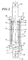
- a probe 10 of the present invention consists of a plunger 12, a barrel 18 and a spring 16.
- the barrel includes an open end 20.
- a contact tip 22 extends from the end of the barrel opposite the barrel open end.
- a flange 24 extends radially outward from the barrel typically at a location near the tip 22.
- the barrel is made from brass and is gold plated, however, other electrically conductive materials can also be used.
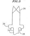
- the plunger also consists of a contact tip 26.
- a flange 28 also extends radially from a location typically at the base of the contact tip.
- the outer surface diameter 30 of the flange formed on the plunger is the same or similar as the outer surface diameter 32 of the flange formed on the barrel.
- the flanges are preferably annular.
- the plunger has a stem 34 that extends axially in a direction opposite the plunger contact tip.
- An enlarged cylindrical surface 36 is formed at the end of the stem defining a bearing.
- the bearing 36 has a diameter slightly smaller than the inner surface diameter of the barrel.
- the bearing is preferably solid, but can also be hollow.
- the plunger is preferably made from BeCu and is also gold plated.
- a crimping surface 38 is formed between the plunger flange and bearing.
- the crimping surface is used to crimp or otherwise bend inward the open end 20 of the barrel, thereby reducing the diameter of the open end.
- the crimping surface does not extend to the perimeter of the plunger flange.
- the distance between the outer edge 40 of the crimping surface and the central axis 42 of the plunger should be at least equal and preferably greater than the inner radius 43 of the barrel. Preferably, such distance should be at least as long as the outer radius 44 of the barrel.
- the crimping surface may be annular, i.e., it may span entirely around the plunger. Alternatively, the crimping surface may span only a portion of the plunger circumference. In such case, multiple crimping surfaces may be formed around the plunger.
- the crimping surface is a frusto-conical surface that surrounds the stem.
- the crimping surface is a section of a frusto conical surface (not shown).
- the crimping surface 38 may be "U" shaped in cross-section for crimping the barrel end by causing it to curl onto itself as shown in FIG. 3.
- a spring 16 having an inner radius 46 greater than the barrel outer surface radius 44 but not greater than the outer surface diameters 30, 32 of the flanges is fitted over the barrel and the plunger between the flanges.
- the spring outer diameter 50 is also not greater than the outer surface diameters 30, 32 of the flanges.
- the spring is preferably made of 302 stainless steel but can be made from other materials.
- the spring inner radius should be longer than the distance 52 between the plunger central axis 42 and the edge 40 of the crimping surface.
- the spring is fitted over the barrel and rests against the barrel flange 24.
- the spring is fitted over the plunger bearing and stem and rests on the plunger flange 28.
- the plunger bearing is then slid into the barrel such that the spring 16. is sandwiched between the barrel flange 24 and the plunger flange 28.
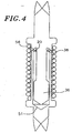
- the barrel and plunger are moved toward each other such that the open end 20 of the barrel is engaged by the crimping surface 38 (FIG. 4).
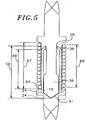
- the edges 56 of the barrel open end are forced to bend or crim radially inward by the crimping surface 38 (FIG. 5).
- the end of the barrel is crimped, it provides a barrier for retaining the bearing 36 within the barrel 18 as the plunger is biased by the spring from the barrel.
- the crimping surface is a frusto-conical surface (see FIGS. 2, 4 and 5)
- the frusto-conical crimping surface provides a radially inward force on the open end of the barrel as the barrel and plunger are compressed toward each other. The movement of the plunger toward the barrel is stopped when the bearing contacts the base surface 51 of the barrel.
- the combined length 58 of the stem and bearing as measured from the base of the stem beginning at the intersection between the stem and the crimping surface can be used to control the amount of crimping of the barrel end. For example, the shorter the combined length, the more crimping that will occur, i.e., a longer portion of the barrel end will be bent inwards.
- the length of the bent portion of the barrel end can be controlled so as to not impinge on the stem.
- the crimping surface does not span entirely around the plunger, the crimping surface will only crimp a portion of the barrel end.
- opposite sections of the barrel should be crimped for retaining the bearing. This is achieved by having crimping surfaces extending opposite each other on the plunger.
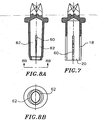
- longitudinal slits 60 may be formed along the barrel extending to the barrel end 20 as shown in FIG. 7. Two or more slits equidistantly spaced are preferred.
- the slits divide the barrel open end into sections 62 and also facilitate the radially inward crimping of the cylindrical barrel open end surface as shown in FIG. 8A.
- the sections 62 of the barrel end between the slits can be bent toward each other, thereby narrowing the diameter of the barrel end 20 to a dimension smaller than the diameter of the bearing and thus provide a barrier for retaining the bearing within the barrel.
- These sections may also be crimped as shown in FIGS 8A and 8B.
- the barrel sections 62 are pre-bent inward and/or their ends are pre-bent (i.e., pre-crimped) inward prior to engagement with the bearing. At least one of the sections and preferably all of the sections 62 of the barrel open end defined between the slits are pre-bent inward and/or pre-crimped as shown in FIGS. 8A and 8B.
- the barrel end sections between the slits can flex. To assemble the probe, the bearing is pushed through the pre-bent and/or pre-crimped open end flexing the pre-bent and/or pre-crimped sections outward.
- the pre-bent and/or pre-crimped end sections flex back inward to their original pre-bent and/or pre-crimped position so that the pre-bent and/or pre-crimped end section(s) provides a barrier for retaining the bearing in the barrel.
- the plunger bearing is "snapped" into position inside the barrel.
- the barrel or plunger of the probe may each comprise multiple portions.
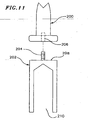
- the tip and flange of a barrel may form one portion 200 while the barrel hollow section may form a second portion 202 (FIG. 11).
- the barrel hollow portion may have a stud 204 extending from its end 208 opposite its open end 210.
- the tip and flange portion may have an axial opening 206 formed along the central axis of the flange and tip beginning at the flange and continuing into the tip.
- the stud 204 is fitted into the opening 206.
- the stud may be threaded to the opening or it may be press fitted into the opening, or the tip and flange portion may be crimped after the stud is fitted into the opening causing the inner surface of the opening 206 to lock on the stud.
- Other methods of connecting the portions may also be used which do not incorporate the use of a stud protruding through the barrel hollow portion or an opening in the flange and tip portion.
- a multiple portion barrel or plunger allows for the spring to be fitted over the barrel and plunger after the barrel end is crimped.
- the bearing of the plunger may be fitted into the barrel hollow portion through the hollow portion open end. The hollow portion open end is then crimped. A spring is then placed over the barrel hollow portion and is pushed against the flange of the plunger. The barrel tip and flange portion is then attached to the barrel hollow portion.
- a two portion plunger may be used where the plunger tip and flange form the first portion and the stem and bearing form the second portion. In such case, after the barrel open end is crimped retaining the plunger bearing, the spring is fitted over the plunger and barrel and is pushed against the barrel flange. The plunger tip and flange portion is then attached to the bearing and stem portion. Consequently, with these embodiments, the spring does not have to be compressed to expose the barrel open end to allow for crimping.
- the spring length 67 when compressed may be longer than the length of the barrel as measured from the barrel flange surface 64 that supports the spring to the barrel open end.
- the uncrimped length 66 of the barrel may be shorter than the length of the spring solid height 67 (FIG. 5).
- the fully compressed spring length must be shorter than the length of the barrel to accommodate the plunger bearing(s).
- a shorter barrel lenght can be used for a given spring length.
- a shorter probe may be used having a shorter electrical interconnect without decreasing the spring length.
- the spring is external to the interconnect, for a given spring height, the spring is more voluminous than an internal spring because it has a larger spring diameter and therefore a longer wire length.
- a longer spring may be used further increasing the spring volume and thus, the spring operating life without decreasing the spring compliance.
- moving a flange closer to its respective tip allows the length of the probe to be shortened without decreasing the spring length and compliance.
- the probe is biased laterally, i.e., that a bending force is applied to the probe attempting to bend the probe along its length.
- this is accomplished by using a spring whose ends are not squared off such that the length 67 of the spring along one side of the barrel is longer than the length 69 of the spring along an opposite side of the barrel (FIG. 5). This is achieved by using a spring which begins and ends at the same side of the barrel.
- the force applied on the plunger by the spring is greater on one side of the barrel (i.e., the side where the spring is longer) causing the plunger to extend along an axis skewed from the center of the barrel causing the bearing to maintain contact with the inner surface of the barrel.
- An exemplary probe of the present invention has a length 68 when fully biased by the spring of about 3.3 mm (0.13 inch) as measured from the plunger tip to the barrel tip (FIG. 6).
- the length of the exemplary probe when fully compressed is 2.5 mm (0.1 inch).
- the exemplary probe has a travel or compliance of about 0.76 mm (0.030 inch) between the barrel and plunger with a spring force of about 28 g(1 ounce) at about 0.51 mm (0.020 inch) travel.
- the probes are typically fitted in cavities 100 defined in sockets (or test plates) 102 (FIG.9). These cavities have a diameter 104 to accommodate the probes with external springs. At an end face 106 of the socket, each cavity narrows to an opening 108 to allow for penetration by the probe tip. The narrowing of the cavities define shoulders 110 inside the cavities. Once the probes are inserted into the cavities their plunger flanges 28 engage the cavity shoulders 110 while their plunger tips 26 protrude beyond the socket through openings 108. A cover plate 112 having openings 114 in the same pattern as the openings 108 on the test socket is mated to the test socket such that the barrel tips 22 of the probe protrude through the openings 114 of the cover plate.
- the openings formed on the cover plate have a diameter larger than the diameter of the tips but smaller than the outer diameter of the flanges.
- the cover plate engages the barrel flanges 24 when the probes are extended. Consequently, the sockets with the cover plate may serve to limit the extension of the probes.
- the probes may also be mounted with their barrel tips 22 penetrating the socket openings 108 and their plunger tips 26 penetrating the cover plate openings 114.
- the probes of the present invention do not have their barrel ends 20 crimped.
- each plunger is placed in a socket cavity 100.
- a spring 16 is then inserted over the plunger followed by a barrel which is pushed into the cavity to externally engage the plunger.
- the cover plate 112 is then mated to the socket.
- the shoulders 110 formed in the cavities and the cover plate 112 serve to keep the probe together.
- a probe of this embodiment does not require a separate bearing surface. Rather, the stem 34 can act as the bearing surface for bearing against the barrel inner walls (FIG.10). With this embodiment, the diameter of the stem is slightly smaller than the inner diameter of the barrel.
- the contact plate i.e., the circuit board
- the circuit board to be tested may be used to close off the cavities 100 such that the contact points on the circuit board to be tested come in contact with the probe tips.
- the socket may only have cylindrical cavities 300 as shown in FIG. 13.
- the circuit board to be tested 302 is mated to one side of the socket with its contact points 304 making contact with the probe tips 324 of an arrangement which does not form part of the present invention.
- the contact plate 113 coupled to the test equipment 117 is mated to the opposite side of the socket whereby the circuit board and contact plate restrain the probes within the cavities.
- all of the aforementioned probe embodiments allow for an increase in the spring volume without decreasing the spring compliance, and also allow for a decrease in the electrical interconnect length without decreasing the probe spring volume.
Landscapes
- Physics & Mathematics (AREA)
- General Physics & Mathematics (AREA)
- Measuring Leads Or Probes (AREA)
- Ultra Sonic Daignosis Equipment (AREA)
- Measurement Of The Respiration, Hearing Ability, Form, And Blood Characteristics Of Living Organisms (AREA)
- Geophysics And Detection Of Objects (AREA)
- Springs (AREA)
- Cable Accessories (AREA)
- Testing Or Measuring Of Semiconductors Or The Like (AREA)
- Testing Of Individual Semiconductor Devices (AREA)
Claims (19)
- Federmesskopf
mit einer Hülse (18), die eine Federstützfläche (24), die sich von dort erstreckt, und ein offenes Hülsenende (20) aufweist,
mit einem Kolben (12), der sich abschnittsweise durch das offene Hülsenende (20) in die Hülse erstreckt und eine Federstützfläche (28) aufweist, die sich von diesem erstreckt, und mit
einer Feder (16), die zwischen den beiden Flächen (24, 28) eingesetzt ist, wobei die Feder den Kolben umgibt und den Kolben von der Hülse weg vorspannt. - Federmesskopf nach Anspruch 1, wobei sich die Feder (16) über die Hülse (18) zu der Federstützfläche (28) des Kolbens erstreckt, wenn sie vollkommen zusammengedrückt ist.
- Federmesskopf nach Anspruch 1 oder Anspruch 2, wobei sich der Kolben (12) während einer Stauchbewegung und während einer Streckbewegung des Kolbens relativ zu dem Kolben (18) über einen Weg bewegt und wobei die Länge (67) der Feder (16) größer als der maximale Weg ist, über die sich der Kolben während einer der Bewegungen bewegt, wenn sie vollkommen zusammengedrückt wird.
- Federmesskopf nach einem der Ansprüche 1 bis 3, der weiterhin eine Einrichtung (38) auf dem Kolben aufweist, um zumindest einen Teil des offenen Hülsenendes (20) umzubiegen, wenn der Kolben (12) zu der Hülse (18) bewegt wird, um einen Teil des Kolbens in der Hülse zurückzuhalten.
- Federmesskopf nach einem der Ansprüche 1 bis 3, wobei der Kolben eine Umbiegefläche (38) aufweist, um das offene Ende (20) der Hülse während der anfänglichen Stauchbewegung des Kolbens umzubiegen.
- Federmesskopf nach einem der Ansprüche 1 bis 5, wobei die Hülse außerdem Schlitze (60) aufweist, die sich in Längsrichtung zu dem offenen Hülsenende (20) erstrecken und zwei Abschnitte (62) an dem offenen Ende bilden, und zwar einen auf jeder Seite des Schlitzes, wobei zumindest ein Abschnitt nach innen gebogen ist und wobei der Kolben an einem Ende eine Spitze (26),
einen Schaft (34), der sich gegenüber der Spitze (26) erstreckt und
einen Lagerabschnitt (36) aufweist, der sich von dem Schaft gegenüber der Spitze erstreckt und gleitfähig in die Hülse (18) eingepasst ist, wobei der Lagerabschnitt (36) breiter als der Schaft (34) ist und wobei der gebogene Abschnitt das Lager in der Hülse zurückhält. - Federmesskopf nach Anspruch 6, wobei der Lagerabschnitt (36) in der Hülse (18) eingepasst wird, indem er durch das offene Hülsenende (20) und an dem gebogenen Abschnitt (62) der Hülse vorbei eingeführt wird.
- Federmesskopf nach Anspruch 6 oder Anspruch 7, der weiterhin wenigstens einen weiteren Schlitz (60) aufweist, der sich zum offenen Hülsenende (20) erstreckt, wodurch das offene Ende (20) in wenigstens zwei Abschnitte (62) geteilt wird, wobei sich jeder Abschnitt zwischen den beiden Schlitzen erstreckt und wobei einer der Abschnitte der nach innen gebogene Abschnitt ist.
- Federmesskopf nach Anspruch 8, wobei die wenigstens zwei Abschnitte (62) nach innen gebogen sind.
- Federmesskopf nach einem der Ansprüche 6 bis 9, wobei der Schlitz (60) das Biegen des gebogenen Abschnitts (62) nach innen erleichtert.
- Federmesskopf nach einem der Ansprüche 1 bis 5, wobei die Hülse (18) ein geschlossenes Ende aufweist und wobei sich die Federstützfläche (24) der Hülse radial von der Hülse (18) nach außen erstreckt, wobei der Kolben (12) an einem Ende eine Spitze (26), wobei sich die Federstützfläche (28) des Kolbens von dem Kolben radial nach außen erstreckt,
einen Schaft (34), der sich gegenüber der Spitze (26) erstreckt,
einen Lagerabschnitt (36), das sich von dem Schaft (34) gegenüber der Spitze (26) erstreckt und gleitfähig in der Hülse (18) eingepasst ist, wobei der Lagerabschnitt (36) breiter als der Schaft (34) ist, und
eine weitere Fläche (38) aufweist, die sich radial von dem Kolben (12) nach außen und zu dem Lagerabschnitt (36) erstreckt, um in das offene Ende (20) des Kolbens einzugreifen und dieses Ende zu veranlassen, sich radial nach innen zu biegen, um den Lagerabschnitt (36) in der Hülse (18) zurückzuhalten. - Federmesskopf nach Anspruch 11, wobei die Hülse weiterhin wenigstens einen Schlitz (60) aufweist, der sich länglich zu dem offenen Ende (20) der Hülse erstreckt, um das Biegen des offenen Endes nach innen zu erleichtern.
- Federmesskopf nach Anspruch 11 oder 12, wobei die Hülse eine Spitze (22) aufweist, die sich von dem geschlossenen Ende der Hülse in eine Richtung erstreckt, die dem offenen Hülsenende (20) gegenüberliegt.
- Federmesskopf nach einem der Ansprüche 1 bis 13, wobei die Hülse (14), der Kolben (12) und die Feder (16) eine unlösbare Anordnung bilden.
- Federmesskopf nach einem der Ansprüche 1 bis 14, der in eine Muffe (102) eingepasst ist, wobei die Muffe eine erste Seite, eine zweite Seite und dazwischen einen Dickenabschnitt sowie in dem Dickenabschnitt einen Hohlraum (100) aufweist, der eine Öffnung auf jeder Seite der Muffe bildet, wobei der Federmesskopf in dem Hohlraum eingepasst ist, wobei eine erste Einrichtung (112) an einer ersten Seite der Muffe die Hohlraumöffnung an der ersten Seite begrenzt und wobei eine zweite Einrichtung (106) an der zweiten Seite der Muffe die Hohlraumöffnung an der zweiten Seite der Hülse begrenzt.
- Verfahren zum Zusammenbau eines Federmesskopfes mit einer Hülse (18), die ein offenes Ende (20) und eine Fläche (24) aufweist, die sich radial von einem Ort entfernt von dem offenen Hülsenende (20) nach außen erstreckt, und mit einem Kolben (12), der über einen Lagerabschnitt (36), über eine Spitze (26) gegenüber dem Lagerelement und über eine erste Fläche (38) sowie eine zweite Fläche (28) verfügt, die sich von dem Kolben zwischen der Spitze und dem Lagerelement nach außen erstreckt, wobei das Verfahren die Schritte des
Einsetzens einer Feder (16) um die Hülse zwischen der Fläche (24) der Hülse und der zweiten Fläche (28) des Kolbens,
des Einpassens des Lagerabschnitts (36) in den Kolben (14) und
des Zusammendrückens des Kolbens in der Hülse aufweist, wodurch die erste Fläche (38) veranlasst wird, zumindest ein Teil des offenen Endes (20) der Hülse nach innen zu biegen. - Verfahren nach Anspruch 16, wobei die Hülse wenigstens zwei Schlitze (60) aufweist, die an der Hülse ausgebildet sind, sich zu dem offenen Ende (20) erstrecken und wenigstens zwei Hülsenabschnitte (62) bilden, wobei das Verfahren außerdem das Biegen von wenigstens einem Abschnitt (62) nach innen aufweist, um den Durchmesser des offenen Hülsenendes vor dem Zusammendrücken zu verringern.
- Verfahren nach Anspruch 17, wobei der Kolben einen Lagerabschnitt (36) aufweist, der sich von einem Schaft (34) erstreckt, der schmaler als der Lagerabschnitt ist, wobei das Zusammendrücken das Einschieben des Lagerabschnittes in die Hülse durch das offene Ende (20) umfasst, wodurch der gebogene Abschnitt veranlasst wird, sich nach außen und dann nach innen zu biegen, wenn der Lagerabschnitt (36) an dem gebogenen Abschnitt vorbeigeschoben wird, wobei der gebogene Abschnitt den Lagerabschnitt in der Hülse zurückhält.
- Verfahren nach einem der Ansprüche 16 bis 18, wobei die Hülse (18) gegenüber dem offenen Ende (20) eine Spitze (22) aufweist.
Priority Applications (1)
| Application Number | Priority Date | Filing Date | Title |
|---|---|---|---|
| EP04078167A EP1510827B1 (de) | 1999-02-18 | 1999-04-13 | Federsensor |
Applications Claiming Priority (2)
| Application Number | Priority Date | Filing Date | Title |
|---|---|---|---|
| US09/253,320 US6396293B1 (en) | 1999-02-18 | 1999-02-18 | Self-closing spring probe |
| US253320 | 1999-02-18 |
Related Child Applications (1)
| Application Number | Title | Priority Date | Filing Date |
|---|---|---|---|
| EP04078167A Division EP1510827B1 (de) | 1999-02-18 | 1999-04-13 | Federsensor |
Publications (3)
| Publication Number | Publication Date |
|---|---|
| EP1037055A2 EP1037055A2 (de) | 2000-09-20 |
| EP1037055A3 EP1037055A3 (de) | 2001-03-28 |
| EP1037055B1 true EP1037055B1 (de) | 2006-04-05 |
Family
ID=22959787
Family Applications (2)
| Application Number | Title | Priority Date | Filing Date |
|---|---|---|---|
| EP99302847A Expired - Lifetime EP1037055B1 (de) | 1999-02-18 | 1999-04-13 | Federsensor |
| EP04078167A Expired - Lifetime EP1510827B1 (de) | 1999-02-18 | 1999-04-13 | Federsensor |
Family Applications After (1)
| Application Number | Title | Priority Date | Filing Date |
|---|---|---|---|
| EP04078167A Expired - Lifetime EP1510827B1 (de) | 1999-02-18 | 1999-04-13 | Federsensor |
Country Status (7)
| Country | Link |
|---|---|
| US (1) | US6396293B1 (de) |
| EP (2) | EP1037055B1 (de) |
| JP (1) | JP3210645B2 (de) |
| AT (2) | ATE322691T1 (de) |
| DE (2) | DE69930717T2 (de) |
| GB (1) | GB2347023B (de) |
| TW (1) | TW528871B (de) |
Families Citing this family (68)
| Publication number | Priority date | Publication date | Assignee | Title |
|---|---|---|---|---|
| JP4060919B2 (ja) * | 1997-11-28 | 2008-03-12 | 富士通株式会社 | 電気的接続装置、接触子製造方法、及び半導体試験方法 |
| JP3626609B2 (ja) | 1998-10-30 | 2005-03-09 | 日本電気株式会社 | マルチプロセッサシステム |
| JP4450397B2 (ja) * | 1999-06-03 | 2010-04-14 | 有限会社清田製作所 | 両端摺動型コンタクトプローブ |
| US6524251B2 (en) | 1999-10-05 | 2003-02-25 | Omnisonics Medical Technologies, Inc. | Ultrasonic device for tissue ablation and sheath for use therewith |
| US20040097996A1 (en) | 1999-10-05 | 2004-05-20 | Omnisonics Medical Technologies, Inc. | Apparatus and method of removing occlusions using an ultrasonic medical device operating in a transverse mode |
| US6551337B1 (en) | 1999-10-05 | 2003-04-22 | Omnisonics Medical Technologies, Inc. | Ultrasonic medical device operating in a transverse mode |
| JP4889183B2 (ja) * | 2000-06-16 | 2012-03-07 | 日本発條株式会社 | マイクロコンタクタプローブと電気プローブユニット |
| JP4521106B2 (ja) * | 2000-09-28 | 2010-08-11 | 日本発條株式会社 | 可動ガイドプレート付き導電性接触子 |
| JP2002159913A (ja) * | 2000-11-22 | 2002-06-04 | Shin Etsu Polymer Co Ltd | コネクタ付きバイブレータ及びその接続構造 |
| JP3767810B2 (ja) * | 2001-04-27 | 2006-04-19 | 株式会社ヨコオ | スプリングコネクタ |
| JP2002350463A (ja) * | 2001-05-23 | 2002-12-04 | Sanyu Kogyo Kk | コンタクトプローブ |
| KR20040087341A (ko) * | 2002-03-05 | 2004-10-13 | 리카 일렉트로닉스 인터내셔널, 인크. | 전자 패키지와 테스트 장비를 인터페이싱시키기 위한 장치 |
| KR100840834B1 (ko) * | 2002-06-05 | 2008-06-23 | 이노우에 쇼지 가부시키가이샤 | 프린트 배선판의 검사지그 |
| US20040210140A1 (en) * | 2003-04-15 | 2004-10-21 | Omnisonics Medical Technologies, Inc. | Apparatus and method for preshaped ultrasonic probe |
| JP4695337B2 (ja) * | 2004-02-04 | 2011-06-08 | 日本発條株式会社 | 導電性接触子および導電性接触子ユニット |
| US7794414B2 (en) | 2004-02-09 | 2010-09-14 | Emigrant Bank, N.A. | Apparatus and method for an ultrasonic medical device operating in torsional and transverse modes |
| KR100608232B1 (ko) * | 2004-05-17 | 2006-08-03 | 리노공업주식회사 | 대전류용 프로브 |
| US7315176B2 (en) * | 2004-06-16 | 2008-01-01 | Rika Denshi America, Inc. | Electrical test probes, methods of making, and methods of using |
| KR100584225B1 (ko) * | 2004-10-06 | 2006-05-29 | 황동원 | 전자장치용 콘택트 |
| CN101501509B (zh) * | 2005-06-10 | 2013-08-14 | 特拉华资本组成公司 | 具有柔性内互连件的电接触探针 |
| US7154286B1 (en) * | 2005-06-30 | 2006-12-26 | Interconnect Devices, Inc. | Dual tapered spring probe |
| US7392946B2 (en) * | 2006-06-12 | 2008-07-01 | Sony Ericsson Mobile Communications Ab | Mobile radio terminal having a multiple form factor memory card reader |
| US20080143367A1 (en) * | 2006-12-14 | 2008-06-19 | Scott Chabineau-Lovgren | Compliant electrical contact having maximized the internal spring volume |
| KR100769891B1 (ko) * | 2007-01-25 | 2007-10-24 | 리노공업주식회사 | 검사용 탐침 장치 및 이를 이용한 검사용 소켓 |
| JP5713559B2 (ja) * | 2007-04-27 | 2015-05-07 | 日本発條株式会社 | 導電性接触子 |
| US7521949B2 (en) * | 2007-05-07 | 2009-04-21 | Intel Corporation | Test pin, method of manufacturing same, and system containing same |
| US7862391B2 (en) * | 2007-09-18 | 2011-01-04 | Delaware Capital Formation, Inc. | Spring contact assembly |
| US8410948B2 (en) * | 2008-05-12 | 2013-04-02 | John Vander Horst | Recreational vehicle holding tank sensor probe |
| KR101235228B1 (ko) * | 2008-08-08 | 2013-02-20 | 니혼 하츠쵸 가부시키가이샤 | 워크 부재, 전기 접점 부재, 콘택트 프로브 및 전기 접점 부재의 제조방법 |
| TWM354896U (en) * | 2008-09-30 | 2009-04-11 | Hon Hai Prec Ind Co Ltd | Terminal of electrical connector |
| JP5291585B2 (ja) * | 2008-11-07 | 2013-09-18 | 株式会社日本マイクロニクス | 接触子及び電気的接続装置 |
| JP4900843B2 (ja) | 2008-12-26 | 2012-03-21 | 山一電機株式会社 | 半導体装置用電気接続装置及びそれに使用されるコンタクト |
| WO2010104913A1 (en) * | 2009-03-10 | 2010-09-16 | Johnstech International | Electrically conductive pins for microcircuit tester |
| US20130002285A1 (en) | 2010-03-10 | 2013-01-03 | Johnstech International Corporation | Electrically Conductive Pins For Microcircuit Tester |
| JP5361518B2 (ja) * | 2009-04-27 | 2013-12-04 | 株式会社ヨコオ | コンタクトプローブ及びソケット |
| JPWO2011096067A1 (ja) * | 2010-02-05 | 2013-06-10 | 株式会社日本マイクロニクス | 接触子及び電気的接続装置 |
| KR101149758B1 (ko) * | 2010-06-30 | 2012-07-11 | 리노공업주식회사 | 프로브 |
| TWI534432B (zh) * | 2010-09-07 | 2016-05-21 | 瓊斯科技國際公司 | 用於微電路測試器之電氣傳導針腳 |
| US9007082B2 (en) | 2010-09-07 | 2015-04-14 | Johnstech International Corporation | Electrically conductive pins for microcircuit tester |
| CN102466740A (zh) * | 2010-11-12 | 2012-05-23 | 金英杰 | 半导体开尔文测试探针 |
| WO2012067126A1 (ja) * | 2010-11-17 | 2012-05-24 | 日本発條株式会社 | コンタクトプローブおよびプローブユニット |
| JP2012112709A (ja) * | 2010-11-22 | 2012-06-14 | Unitechno Inc | ケルビンコンタクトプローブおよびそれを備えたケルビン検査治具 |
| JP5782261B2 (ja) | 2011-01-17 | 2015-09-24 | 株式会社ヨコオ | ソケット |
| JP5097968B1 (ja) * | 2011-08-02 | 2012-12-12 | 株式会社クローバーテクノロジー | 異方導電性部材 |
| JP6009544B2 (ja) * | 2012-04-17 | 2016-10-19 | ユニテクノ株式会社 | ケルビンコンタクトプローブおよびそれを備えたケルビン検査治具 |
| US9128121B2 (en) * | 2012-09-28 | 2015-09-08 | Intel Corporation | Mechanism for facilitating a dynamic electro-mechanical interconnect having a cavity for embedding electrical components and isolating electrical paths |
| KR101439343B1 (ko) * | 2013-04-18 | 2014-09-16 | 주식회사 아이에스시 | 포고핀용 탐침부재 |
| KR101439342B1 (ko) | 2013-04-18 | 2014-09-16 | 주식회사 아이에스시 | 포고핀용 탐침부재 |
| JP2015004614A (ja) * | 2013-06-21 | 2015-01-08 | 株式会社ミタカ | コンタクトプローブ |
| SG11201700936RA (en) | 2014-08-08 | 2017-03-30 | Nhk Spring Co Ltd | Connecting terminal |
| KR101591013B1 (ko) * | 2014-09-29 | 2016-02-03 | (주) 네스텍코리아 | 셀프결합형 프로브 핀 |
| DE102015102031B4 (de) * | 2015-02-12 | 2017-12-14 | Ptr Messtechnik Gmbh | Verfahren zur Montage eines eine Hülse, einen Kolben mit Kolbenkopf und eine Feder aufweisenden Bauteiles sowie Bauteil |
| KR101785605B1 (ko) * | 2015-09-24 | 2017-10-17 | (주)엠투엔 | 상호 접속 구조체 및 이를 포함하는 프로브 카드 |
| KR101785591B1 (ko) * | 2015-09-24 | 2017-10-17 | (주)엠투엔 | 상호 접속 구조체 및 이를 포함하는 프로브 카드 |
| JP6556612B2 (ja) * | 2015-12-04 | 2019-08-07 | ルネサスエレクトロニクス株式会社 | 半導体装置の製造方法 |
| JP6837283B2 (ja) * | 2016-02-29 | 2021-03-03 | 株式会社ヨコオ | ソケット |
| HUP1700051A2 (hu) | 2017-02-02 | 2018-08-28 | Equip Test Kft | Kontaktáló eszköz, fejegység ahhoz, valamint eljárások kontaktáló eszköz és fejegység elõállítására |
| JP6892277B2 (ja) * | 2017-02-10 | 2021-06-23 | 株式会社日本マイクロニクス | プローブ及び電気的接続装置 |
| JP6969929B2 (ja) * | 2017-08-24 | 2021-11-24 | 株式会社日本マイクロニクス | プローブ及びその製造方法 |
| JP6889067B2 (ja) * | 2017-08-24 | 2021-06-18 | 株式会社日本マイクロニクス | 電気的接続装置 |
| JP7141796B2 (ja) | 2018-09-26 | 2022-09-26 | 株式会社エンプラス | コンタクトピン及びソケット |
| JP7274853B2 (ja) * | 2018-12-03 | 2023-05-17 | 株式会社エンプラス | コンタクトピンおよびソケット |
| JP6837513B2 (ja) * | 2019-05-07 | 2021-03-03 | 株式会社ヨコオ | ソケット |
| JP6923821B2 (ja) * | 2019-09-06 | 2021-08-25 | 山一電機株式会社 | コンタクトプローブ及びこれを備えた検査用ソケット |
| JP7136362B2 (ja) * | 2019-10-04 | 2022-09-13 | 株式会社村田製作所 | プローブ |
| DE102021120146A1 (de) | 2021-08-03 | 2023-02-09 | F I X T E S T Prüfmittelbau GmbH | Kontaktstift |
| CN115877169A (zh) * | 2021-09-27 | 2023-03-31 | 史密斯互连美洲公司 | 用于半导体集成电路的具有阶梯环的测试插座和探针 |
| USD1090440S1 (en) | 2023-01-12 | 2025-08-26 | Johnstech International Corporation | Spring probe contact assembly |
Family Cites Families (18)
| Publication number | Priority date | Publication date | Assignee | Title |
|---|---|---|---|---|
| GB1324053A (en) | 1971-09-09 | 1973-07-18 | Carr V | Electrical contact probe |
| US3754731A (en) * | 1972-01-18 | 1973-08-28 | Halkey Roberts Corp | Inflation manifold valve and flange assembly |
| FR2224757A1 (en) | 1973-04-03 | 1974-10-31 | Cit Alcatel | Probe for printed circuit boards - mounted on subsidiary board in desired spatial arrangement for testing |
| US4438397A (en) * | 1979-12-26 | 1984-03-20 | Teradyne, Inc. | Test pin |
| US4740746A (en) | 1984-11-13 | 1988-04-26 | Tektronix, Inc. | Controlled impedance microcircuit probe |
| JPS6212875A (ja) | 1985-07-10 | 1987-01-21 | Mitsubishi Electric Corp | デイジタル保護継電装置の試験装置 |
| US4701700A (en) | 1985-12-02 | 1987-10-20 | Jenkins Jack E | Captivated, pre-loaded spring means for vacuum displaced circuit board testing |
| US4897043A (en) * | 1986-06-23 | 1990-01-30 | Feinmetall Gmbh | Resilient contact pin |
| US4935695A (en) | 1988-07-13 | 1990-06-19 | Hewlett-Packard Company | Board alignment system |
| US4904213A (en) | 1989-04-06 | 1990-02-27 | Motorola, Inc. | Low impedance electric connector |
| EP0462706A1 (de) | 1990-06-11 | 1991-12-27 | ITT INDUSTRIES, INC. (a Delaware corporation) | Kontaktanordnung |
| US5174763A (en) | 1990-06-11 | 1992-12-29 | Itt Corporation | Contact assembly |
| US5227718A (en) * | 1992-03-10 | 1993-07-13 | Virginia Panel Corporation | Double-headed spring contact probe assembly |
| JP2532331B2 (ja) | 1992-11-09 | 1996-09-11 | 日本発条株式会社 | 導電性接触子 |
| EP0616394A1 (de) | 1993-03-16 | 1994-09-21 | Hewlett-Packard Company | Verfahren und Vorrichtung für die Herstellung von elektrisch zusammengeschalteten Schaltungen |
| US5746606A (en) * | 1996-09-30 | 1998-05-05 | Hughes Electronics | Spring loaded contact device and rotary connector |
| EP0838878B1 (de) * | 1997-02-04 | 1999-02-24 | Durtal SA | Federkontaktelement |
| US6104205A (en) * | 1998-02-26 | 2000-08-15 | Interconnect Devices, Inc. | Probe with tab retainer |
-
1999
- 1999-02-18 US US09/253,320 patent/US6396293B1/en not_active Expired - Lifetime
- 1999-03-16 GB GB9905858A patent/GB2347023B/en not_active Expired - Lifetime
- 1999-04-03 TW TW088105387A patent/TW528871B/zh not_active IP Right Cessation
- 1999-04-13 EP EP99302847A patent/EP1037055B1/de not_active Expired - Lifetime
- 1999-04-13 AT AT99302847T patent/ATE322691T1/de not_active IP Right Cessation
- 1999-04-13 DE DE69930717T patent/DE69930717T2/de not_active Expired - Lifetime
- 1999-04-13 DE DE69936893T patent/DE69936893T2/de not_active Expired - Lifetime
- 1999-04-13 AT AT04078167T patent/ATE370419T1/de not_active IP Right Cessation
- 1999-04-13 EP EP04078167A patent/EP1510827B1/de not_active Expired - Lifetime
- 1999-06-07 JP JP15944299A patent/JP3210645B2/ja not_active Expired - Lifetime
Also Published As
| Publication number | Publication date |
|---|---|
| DE69930717T2 (de) | 2007-01-25 |
| HK1035030A1 (en) | 2001-11-09 |
| DE69930717D1 (de) | 2006-05-18 |
| HK1033977A1 (en) | 2001-10-05 |
| TW528871B (en) | 2003-04-21 |
| ATE370419T1 (de) | 2007-09-15 |
| EP1510827A1 (de) | 2005-03-02 |
| HK1033976A1 (zh) | 2001-10-05 |
| DE69936893D1 (de) | 2007-09-27 |
| EP1037055A3 (de) | 2001-03-28 |
| EP1037055A2 (de) | 2000-09-20 |
| GB9905858D0 (en) | 1999-05-05 |
| GB2347023A (en) | 2000-08-23 |
| US6396293B1 (en) | 2002-05-28 |
| JP3210645B2 (ja) | 2001-09-17 |
| HK1030455A1 (en) | 2001-05-04 |
| JP2000241447A (ja) | 2000-09-08 |
| GB2347023B (en) | 2001-07-25 |
| DE69936893T2 (de) | 2008-05-15 |
| ATE322691T1 (de) | 2006-04-15 |
| EP1510827B1 (de) | 2007-08-15 |
Similar Documents
| Publication | Publication Date | Title |
|---|---|---|
| EP1037055B1 (de) | Federsensor | |
| EP1299735B1 (de) | Selbsthalterungsfedersonde | |
| US7256593B2 (en) | Electrical contact probe with compliant internal interconnect | |
| US5801544A (en) | Spring probe and method for biasing | |
| US10547135B2 (en) | Spring connector | |
| WO2010123833A1 (en) | Swaging process for improved complaint contact electrical test performance | |
| US8710856B2 (en) | Terminal for flat test probe | |
| US7862391B2 (en) | Spring contact assembly | |
| EP2836847B1 (de) | Testsondenanordnung und zugehörige verfahren | |
| US20100007365A1 (en) | Socket for double ended probe, double ended probe, and probe unit | |
| KR101894965B1 (ko) | 프로브 핀 및 ic 소켓 | |
| US6764318B1 (en) | Self-centering press-fit connector pin used to secure components to a receiving element | |
| EP2411820A1 (de) | Scheuereinleitender konformer elektrischer kontakt | |
| GB2066590A (en) | Test pin | |
| GB2323485A (en) | Hollow plunger test probe | |
| US6271672B1 (en) | Biased BGA contactor probe tip | |
| GB2351398A (en) | Spring probe for testing | |
| US4660922A (en) | Terminal plug body and connector | |
| HK1054984B (en) | Self-retained spring probe |
Legal Events
| Date | Code | Title | Description |
|---|---|---|---|
| PUAI | Public reference made under article 153(3) epc to a published international application that has entered the european phase |
Free format text: ORIGINAL CODE: 0009012 |
|
| AK | Designated contracting states |
Kind code of ref document: A2 Designated state(s): AT BE CH DE DK ES FI FR GR IE IT LI LU MC NL PT SE |
|
| AX | Request for extension of the european patent |
Free format text: AL;LT;LV;MK;RO;SI |
|
| PUAL | Search report despatched |
Free format text: ORIGINAL CODE: 0009013 |
|
| AK | Designated contracting states |
Kind code of ref document: A3 Designated state(s): AT BE CH CY DE DK ES FI FR GB GR IE IT LI LU MC NL PT SE |
|
| AX | Request for extension of the european patent |
Free format text: AL;LT;LV;MK;RO;SI |
|
| 17P | Request for examination filed |
Effective date: 20010725 |
|
| AKX | Designation fees paid |
Free format text: AT BE CH DE DK ES FI FR GR IE IT LI LU MC NL PT SE |
|
| 17Q | First examination report despatched |
Effective date: 20040702 |
|
| RIN1 | Information on inventor provided before grant (corrected) |
Inventor name: JOHNSTON, CHARLES J. Inventor name: CHABINEAU, SCOTT D. Inventor name: VINTHER, GORDON A. |
|
| GRAP | Despatch of communication of intention to grant a patent |
Free format text: ORIGINAL CODE: EPIDOSNIGR1 |
|
| GRAS | Grant fee paid |
Free format text: ORIGINAL CODE: EPIDOSNIGR3 |
|
| GRAA | (expected) grant |
Free format text: ORIGINAL CODE: 0009210 |
|
| AK | Designated contracting states |
Kind code of ref document: B1 Designated state(s): AT BE CH DE DK ES FI FR GR IE IT LI LU MC NL PT SE |
|
| PG25 | Lapsed in a contracting state [announced via postgrant information from national office to epo] |
Ref country code: NL Free format text: LAPSE BECAUSE OF FAILURE TO SUBMIT A TRANSLATION OF THE DESCRIPTION OR TO PAY THE FEE WITHIN THE PRESCRIBED TIME-LIMIT Effective date: 20060405 Ref country code: LI Free format text: LAPSE BECAUSE OF FAILURE TO SUBMIT A TRANSLATION OF THE DESCRIPTION OR TO PAY THE FEE WITHIN THE PRESCRIBED TIME-LIMIT Effective date: 20060405 Ref country code: FI Free format text: LAPSE BECAUSE OF FAILURE TO SUBMIT A TRANSLATION OF THE DESCRIPTION OR TO PAY THE FEE WITHIN THE PRESCRIBED TIME-LIMIT Effective date: 20060405 Ref country code: CH Free format text: LAPSE BECAUSE OF FAILURE TO SUBMIT A TRANSLATION OF THE DESCRIPTION OR TO PAY THE FEE WITHIN THE PRESCRIBED TIME-LIMIT Effective date: 20060405 Ref country code: BE Free format text: LAPSE BECAUSE OF FAILURE TO SUBMIT A TRANSLATION OF THE DESCRIPTION OR TO PAY THE FEE WITHIN THE PRESCRIBED TIME-LIMIT Effective date: 20060405 Ref country code: AT Free format text: LAPSE BECAUSE OF FAILURE TO SUBMIT A TRANSLATION OF THE DESCRIPTION OR TO PAY THE FEE WITHIN THE PRESCRIBED TIME-LIMIT Effective date: 20060405 |
|
| PG25 | Lapsed in a contracting state [announced via postgrant information from national office to epo] |
Ref country code: IE Free format text: LAPSE BECAUSE OF NON-PAYMENT OF DUE FEES Effective date: 20060413 |
|
| REG | Reference to a national code |
Ref country code: CH Ref legal event code: EP |
|
| PG25 | Lapsed in a contracting state [announced via postgrant information from national office to epo] |
Ref country code: MC Free format text: LAPSE BECAUSE OF NON-PAYMENT OF DUE FEES Effective date: 20060430 |
|
| REG | Reference to a national code |
Ref country code: IE Ref legal event code: FG4D |
|
| REF | Corresponds to: |
Ref document number: 69930717 Country of ref document: DE Date of ref document: 20060518 Kind code of ref document: P |
|
| PG25 | Lapsed in a contracting state [announced via postgrant information from national office to epo] |
Ref country code: SE Free format text: LAPSE BECAUSE OF FAILURE TO SUBMIT A TRANSLATION OF THE DESCRIPTION OR TO PAY THE FEE WITHIN THE PRESCRIBED TIME-LIMIT Effective date: 20060705 Ref country code: DK Free format text: LAPSE BECAUSE OF FAILURE TO SUBMIT A TRANSLATION OF THE DESCRIPTION OR TO PAY THE FEE WITHIN THE PRESCRIBED TIME-LIMIT Effective date: 20060705 |
|
| PG25 | Lapsed in a contracting state [announced via postgrant information from national office to epo] |
Ref country code: ES Free format text: LAPSE BECAUSE OF FAILURE TO SUBMIT A TRANSLATION OF THE DESCRIPTION OR TO PAY THE FEE WITHIN THE PRESCRIBED TIME-LIMIT Effective date: 20060716 |
|
| PG25 | Lapsed in a contracting state [announced via postgrant information from national office to epo] |
Ref country code: PT Free format text: LAPSE BECAUSE OF FAILURE TO SUBMIT A TRANSLATION OF THE DESCRIPTION OR TO PAY THE FEE WITHIN THE PRESCRIBED TIME-LIMIT Effective date: 20060905 |
|
| NLV1 | Nl: lapsed or annulled due to failure to fulfill the requirements of art. 29p and 29m of the patents act | ||
| REG | Reference to a national code |
Ref country code: CH Ref legal event code: PL |
|
| ET | Fr: translation filed | ||
| PLBE | No opposition filed within time limit |
Free format text: ORIGINAL CODE: 0009261 |
|
| STAA | Information on the status of an ep patent application or granted ep patent |
Free format text: STATUS: NO OPPOSITION FILED WITHIN TIME LIMIT |
|
| 26N | No opposition filed |
Effective date: 20070108 |
|
| PG25 | Lapsed in a contracting state [announced via postgrant information from national office to epo] |
Ref country code: GR Free format text: LAPSE BECAUSE OF FAILURE TO SUBMIT A TRANSLATION OF THE DESCRIPTION OR TO PAY THE FEE WITHIN THE PRESCRIBED TIME-LIMIT Effective date: 20060706 |
|
| PG25 | Lapsed in a contracting state [announced via postgrant information from national office to epo] |
Ref country code: LU Free format text: LAPSE BECAUSE OF NON-PAYMENT OF DUE FEES Effective date: 20060413 |
|
| REG | Reference to a national code |
Ref country code: FR Ref legal event code: PLFP Year of fee payment: 18 |
|
| REG | Reference to a national code |
Ref country code: FR Ref legal event code: PLFP Year of fee payment: 19 |
|
| REG | Reference to a national code |
Ref country code: FR Ref legal event code: PLFP Year of fee payment: 20 |
|
| PGFP | Annual fee paid to national office [announced via postgrant information from national office to epo] |
Ref country code: DE Payment date: 20180427 Year of fee payment: 20 |
|
| PGFP | Annual fee paid to national office [announced via postgrant information from national office to epo] |
Ref country code: IT Payment date: 20180423 Year of fee payment: 20 Ref country code: FR Payment date: 20180425 Year of fee payment: 20 |
|
| REG | Reference to a national code |
Ref country code: DE Ref legal event code: R071 Ref document number: 69930717 Country of ref document: DE |