EP1037065A1 - Dispositif de suivi de l'état de charge d'une pile d'un appareil électronique - Google Patents
Dispositif de suivi de l'état de charge d'une pile d'un appareil électronique Download PDFInfo
- Publication number
- EP1037065A1 EP1037065A1 EP99830086A EP99830086A EP1037065A1 EP 1037065 A1 EP1037065 A1 EP 1037065A1 EP 99830086 A EP99830086 A EP 99830086A EP 99830086 A EP99830086 A EP 99830086A EP 1037065 A1 EP1037065 A1 EP 1037065A1
- Authority
- EP
- European Patent Office
- Prior art keywords
- charge
- logic
- comph
- compl
- integration
- Prior art date
- Legal status (The legal status is an assumption and is not a legal conclusion. Google has not performed a legal analysis and makes no representation as to the accuracy of the status listed.)
- Granted
Links
- 230000010354 integration Effects 0.000 claims abstract description 20
- 238000009966 trimming Methods 0.000 claims abstract description 12
- 238000012544 monitoring process Methods 0.000 claims abstract description 5
- 230000007704 transition Effects 0.000 claims abstract description 3
- 238000007599 discharging Methods 0.000 claims abstract 2
- 230000003247 decreasing effect Effects 0.000 description 2
- 230000006870 function Effects 0.000 description 2
- 238000010521 absorption reaction Methods 0.000 description 1
- 238000012937 correction Methods 0.000 description 1
- 238000010586 diagram Methods 0.000 description 1
- 230000000694 effects Effects 0.000 description 1
- 238000000034 method Methods 0.000 description 1
- 230000002441 reversible effect Effects 0.000 description 1
Images
Classifications
-
- G—PHYSICS
- G01—MEASURING; TESTING
- G01R—MEASURING ELECTRIC VARIABLES; MEASURING MAGNETIC VARIABLES
- G01R31/00—Arrangements for testing electric properties; Arrangements for locating electric faults; Arrangements for electrical testing characterised by what is being tested not provided for elsewhere
- G01R31/36—Arrangements for testing, measuring or monitoring the electrical condition of accumulators or electric batteries, e.g. capacity or state of charge [SoC]
- G01R31/3644—Constructional arrangements
- G01R31/3648—Constructional arrangements comprising digital calculation means, e.g. for performing an algorithm
-
- G—PHYSICS
- G01—MEASURING; TESTING
- G01R—MEASURING ELECTRIC VARIABLES; MEASURING MAGNETIC VARIABLES
- G01R31/00—Arrangements for testing electric properties; Arrangements for locating electric faults; Arrangements for electrical testing characterised by what is being tested not provided for elsewhere
- G01R31/36—Arrangements for testing, measuring or monitoring the electrical condition of accumulators or electric batteries, e.g. capacity or state of charge [SoC]
- G01R31/382—Arrangements for monitoring battery or accumulator variables, e.g. SoC
Definitions
- the present invention relates to systems for managing power dissipation of electronic devices powered with rechargeable batteries and in particular to indicate, for example on an LCD monitor, the state of charge of the battery.
- This function is commonly carried out by the use of a specific integrated system comprising also a charge counter (Coulomb Counter or briefly CC) which monitors the electric charge that flows in and out of battery, generating a logic interrupt signal every time a certain amount of electric charge crosses the battery, during the charge phase (charge interrupt INCR) as well as during the discharge phase, that is, of powering of the portable apparatus, (discharge interrupt DECR).
- a charge counter Coulomb Counter or briefly CC
- interrupts are algebraically processed by the micro controller of the portable apparatus that obtains an indication of the state of charge of the battery.
- This information is either displayed on the screen in the form for example of an icon with different brightness grades or as a numerical indication of the percentage of charge of the battery or the like.
- the battery current is monitored on a dedicated sensing resistor, connected electrically in series with the battery.
- the voltage drop on this resistor is amplified through a differential amplifier whose output signal is integrated through a dedicated integrator stage.
- a positive or negative ramp is produced at the output of the integrating stage, depending on the current direction (either a charge current or a discharge current).
- the ramp is interrupted by the switching of one or the other of a pair of comparators, one for the positive ramp and the other for the negative ramp, which momentarily closes a discharge switch of the capacitance of integration and thereafter a new ramp begins and so forth. Therefore the switchings of the two comparators generate as many interrupt signals, of one or the other sign, that are fed to two respective counters, or to a unique counter which is incremented by a unit at each charge interrupt or decremented by a unit at every discharge interrupt or vice versa. In either case, the content of the counters or of the reversible counter indicates the state of charge of the battery.
- the quest for minimizing power dissipation motivates the use of a sensing resistor of the battery current of a very small value, typically in the order of few tens of a m ⁇ (for example 50 to 100 m ⁇ ).
- the monitoring of the battery current is to some extent invalidated by the offset of the differential amplifier.
- the amplifier offset sums itself to the voltage drop on the terminals of the sensing resistor and when the battery current is relatively low, for example less than a few tens of m ⁇ , the offset of the amplifier may be of the same order of the real signal.
- the system will continue to integrate the offset and the counter, in absence of specific corrections, would be periodically increased or decreased depending on the sign of the offset thus providing the micro-controller with spurious information.
- a minimum current level is usually established, below which the monitoring of the current is inhibited, thus creating, in practice, a so-called dead zone, typically in the order of few mA.
- the signal level is lower than a certain threshold corresponding to such a set minimum current level of the dead zone, the output signal of the amplifier in not integrated, thus averting the generation of interrupt under conditions that would be in any case grossly affected by the offset.
- the system of the invention is based on the use of a timer that measures the time interval between the start instant of an integration ramp of the output signal of the differential amplifier that monitors the current through the battery and the switching of one or the other comparator, and of a nonvolatile memory register where to permanently store the time interval relative to the integration of the offset established during a trimming step, done by short-circuiting the inputs of the differential amplifier that monitors the current battery.
- a timer that measures the time interval between the start instant of an integration ramp of the output signal of the differential amplifier that monitors the current through the battery and the switching of one or the other comparator
- a nonvolatile memory register where to permanently store the time interval relative to the integration of the offset established during a trimming step, done by short-circuiting the inputs of the differential amplifier that monitors the current battery.
- the offset direction is permanently stored in the memory register by way of a sign bit.
- the system continues to integrate the amplifier offset causing the switching of the relative comparator which, if not compensated for, would unduly increment the relative interrupt counter.
- the relative interrupt counter is decremented by a unit, thus nullifying the increment due a continued integration of the offset.
- the offset is integrated together with the signal present on the sensing resistor terminals, and also in these conditions, when the pre-established and permanently stored time interval lapses, the system decrements the relative interrupt counter by a unit, thus thoroughly compensating any offset effect in computing the interrupts under any current absorption condition.
- system of the invention may also be used to implement an interrupt counter with a dead zone, the extent of which may be defined according to the real offset conditions with a high accuracy.
- a current of 15mA is forced through the sensing resistor.
- the timer measures the time interval (dead zone time) elapsing from the beginning of the integration and the eventual switching of the relative comparator. This information is permanently stored in the nonvolatile memory register.
- the timer at the beginning of each new integration phase counts backward starting from the dead zone limit time.
- the integration time will be greater (or at the most equal to) than the dead zone limit time and the result of the counting will be null, thus impeding an increment of the relative interrupt counter.
- the integration time needed to trigger the relative interrupt counter will be less than the dead zone limit time and the result of the counting will be different from zero. Therefore, the interrupt counter will be correctly increased or decreased upon the switching of the relative comparator.
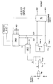
- the attached figure shows a basic diagram of the counter of the invention.
- the counter of the invention for determining the state of charge of a battery comprises a conventional sensing circuit of the charge and discharge current of the battery.
- the summing circuit is composed of a differential amplifier AMP whose inputs are coupled to the terminals of a sensing resistor Rs of the battery current, and of an integrator stage INTEGR, resettable by a switch SW, that integrates the signal output by the amplifier AMP.
- a first comparator CompH compares the ramp output by the integrator with a first threshold VthH. eventually generating a logic charge interrupt signal INCR, while a second comparator CompL compares the same signal output by the integrator with a second threshold VthL, eventually generating a logic discharge interrupt signal DECR.
- the discharge switch SW of the capacitance of integration C of the integrator is momentarily closed by a LOGIC circuit at each transition of the INCR or DECR output signals of either one or the other comparator.
- the counter further comprises a TIMER that is started by a command IN produced by said LOGIC circuit.
- the TIMER measures the interval elapsing between the starting instant of a new ramp of integration and the switching of one or of the other comparator of the pair of comparators CompH and CompL of the sensing circuit.
- An N bit nonvolatile memory REGISTER contains the information of the time interval integration of the amplifier's offset up to switching of one or the other of the two comparators, depending on the direction (sign) of the amplifier's offset, written therein during a trimming step.
- the so stored information includes a sign bit that identifies the direction of the offset of the monitoring amplifier.
- the asynchronous counter N that computes the charge and discharge interrupt signals, INCR and DECR, increments or decrements the computation, depending on the sign of the offset, at the elapsing of each interval of integration of the amplifier's offset, in function of the data permanently stored in the REGISTER.
- a trimming step is commanded by the TEST_MODE command, which also controls the short-circuiting of the inputs of the differential amplifier (SNIP) in order to check the offset.
- the information currently contained in the asynchronous counter N is decremented or incremented by a unit, depending on the stored offset sign.
Landscapes
- Physics & Mathematics (AREA)
- General Physics & Mathematics (AREA)
- Tests Of Electric Status Of Batteries (AREA)
- Charge And Discharge Circuits For Batteries Or The Like (AREA)
- Measurement Of Current Or Voltage (AREA)
- Secondary Cells (AREA)
Priority Applications (4)
| Application Number | Priority Date | Filing Date | Title |
|---|---|---|---|
| EP99830086A EP1037065B1 (fr) | 1999-02-18 | 1999-02-18 | Dispositif de suivi de l'état de charge d'une pile d'un appareil électronique |
| DE69920399T DE69920399D1 (de) | 1999-02-18 | 1999-02-18 | Ladezustandsüberwachungsgerät für ein elektronisches Gerät |
| US09/503,652 US6339315B1 (en) | 1999-02-18 | 2000-02-14 | Measuring counter of the state of charge of the powering battery of an electronic appliance |
| JP2000040810A JP2000241515A (ja) | 1999-02-18 | 2000-02-18 | 電子器具の電力供給用バッテリの充電状態の測定カウンタ |
Applications Claiming Priority (1)
| Application Number | Priority Date | Filing Date | Title |
|---|---|---|---|
| EP99830086A EP1037065B1 (fr) | 1999-02-18 | 1999-02-18 | Dispositif de suivi de l'état de charge d'une pile d'un appareil électronique |
Publications (2)
| Publication Number | Publication Date |
|---|---|
| EP1037065A1 true EP1037065A1 (fr) | 2000-09-20 |
| EP1037065B1 EP1037065B1 (fr) | 2004-09-22 |
Family
ID=8243280
Family Applications (1)
| Application Number | Title | Priority Date | Filing Date |
|---|---|---|---|
| EP99830086A Expired - Lifetime EP1037065B1 (fr) | 1999-02-18 | 1999-02-18 | Dispositif de suivi de l'état de charge d'une pile d'un appareil électronique |
Country Status (4)
| Country | Link |
|---|---|
| US (1) | US6339315B1 (fr) |
| EP (1) | EP1037065B1 (fr) |
| JP (1) | JP2000241515A (fr) |
| DE (1) | DE69920399D1 (fr) |
Cited By (5)
| Publication number | Priority date | Publication date | Assignee | Title |
|---|---|---|---|---|
| FR2826125A1 (fr) * | 2001-06-19 | 2002-12-20 | St Microelectronics Sa | Procede et dispositif de controle de l'etat de charge d'un batterie, en particulier une batterie rechargeable pour un telephone mobile cellulaire |
| EP1343018A1 (fr) * | 2002-03-05 | 2003-09-10 | Dialog Semiconductor GmbH | Dispositif pour la surveillance de l'état de charge d'une batterie |
| WO2004003574A1 (fr) * | 2002-07-01 | 2004-01-08 | Infineon Technologies Ag | Circuit de détection de sous-tension |
| US9270133B2 (en) | 2007-04-02 | 2016-02-23 | Linear Technology Corporation | Monitoring cells in energy storage system |
| US10340558B2 (en) | 2015-02-18 | 2019-07-02 | Audi Ag | Battery cell with monitoring device, and corresponding operating method |
Families Citing this family (9)
| Publication number | Priority date | Publication date | Assignee | Title |
|---|---|---|---|---|
| JP4352656B2 (ja) * | 2002-05-20 | 2009-10-28 | ソニー株式会社 | 電子機器 |
| JP2009206839A (ja) * | 2008-02-27 | 2009-09-10 | Kyocera Corp | 電子機器および電子機器における消費電流測定方法 |
| TWI394971B (zh) * | 2008-09-23 | 2013-05-01 | Ind Tech Res Inst | 電池特性追蹤方法及電路 |
| TWI432948B (zh) * | 2008-10-20 | 2014-04-01 | Wistron Corp | 用於一可攜式電腦系統之電源管理方法及其相關電源供應裝置與可攜式電腦系統 |
| US8901891B2 (en) | 2009-02-25 | 2014-12-02 | Panasonic Corporation | Voltage polarity determination circuit and charge amount measurement circuit |
| WO2010098090A1 (fr) * | 2009-02-25 | 2010-09-02 | パナソニック株式会社 | Circuit de discrimination d'une polarité de tension et circuit de mesure d'une charge électrique |
| CN102393486B (zh) * | 2011-10-31 | 2013-08-21 | 哈尔滨工业大学 | 基于时间数字转换器的锂电池电流检测电路及检测方法 |
| CN103197249A (zh) * | 2012-01-06 | 2013-07-10 | 安凯(广州)微电子技术有限公司 | 低功耗电池电量检测电路 |
| JP5817566B2 (ja) * | 2012-02-02 | 2015-11-18 | 株式会社デンソー | 電力検出システム |
Citations (4)
| Publication number | Priority date | Publication date | Assignee | Title |
|---|---|---|---|---|
| DE4103470A1 (de) * | 1990-02-07 | 1991-08-08 | Sanyo Electric Co | Kapazitaetsberechnungsvorrichtung |
| US5432429A (en) * | 1990-10-23 | 1995-07-11 | Benchmarq Microelectronics, Inc. | System for charging/monitoring batteries for a microprocessor based system |
| US5614902A (en) * | 1994-11-30 | 1997-03-25 | Sgs-Thomson Microelectronics, Inc. | Ratiometric analog to digital converter with automatic offset |
| GB2321714A (en) * | 1997-01-17 | 1998-08-05 | Samsung Electronics Co Ltd | Device for determining remaining battery capacity |
Family Cites Families (5)
| Publication number | Priority date | Publication date | Assignee | Title |
|---|---|---|---|---|
| DE3915982A1 (de) | 1989-05-17 | 1990-11-22 | Basf Ag | Pulslaser |
| CN1027192C (zh) * | 1989-10-25 | 1994-12-28 | 菲利浦光灯制造公司 | 电池充电装置 |
| JPH04334874A (ja) * | 1991-05-13 | 1992-11-20 | Sony Corp | 電池式受信機 |
| US5592069A (en) * | 1992-10-07 | 1997-01-07 | Dallas Semiconductor Corporation | Battery charger |
| US5594345A (en) * | 1994-01-19 | 1997-01-14 | General Electric Company | Battery capacity indicator for mobile medical equipment |
-
1999
- 1999-02-18 EP EP99830086A patent/EP1037065B1/fr not_active Expired - Lifetime
- 1999-02-18 DE DE69920399T patent/DE69920399D1/de not_active Expired - Lifetime
-
2000
- 2000-02-14 US US09/503,652 patent/US6339315B1/en not_active Expired - Lifetime
- 2000-02-18 JP JP2000040810A patent/JP2000241515A/ja active Pending
Patent Citations (4)
| Publication number | Priority date | Publication date | Assignee | Title |
|---|---|---|---|---|
| DE4103470A1 (de) * | 1990-02-07 | 1991-08-08 | Sanyo Electric Co | Kapazitaetsberechnungsvorrichtung |
| US5432429A (en) * | 1990-10-23 | 1995-07-11 | Benchmarq Microelectronics, Inc. | System for charging/monitoring batteries for a microprocessor based system |
| US5614902A (en) * | 1994-11-30 | 1997-03-25 | Sgs-Thomson Microelectronics, Inc. | Ratiometric analog to digital converter with automatic offset |
| GB2321714A (en) * | 1997-01-17 | 1998-08-05 | Samsung Electronics Co Ltd | Device for determining remaining battery capacity |
Cited By (8)
| Publication number | Priority date | Publication date | Assignee | Title |
|---|---|---|---|---|
| FR2826125A1 (fr) * | 2001-06-19 | 2002-12-20 | St Microelectronics Sa | Procede et dispositif de controle de l'etat de charge d'un batterie, en particulier une batterie rechargeable pour un telephone mobile cellulaire |
| US6680615B2 (en) | 2001-06-19 | 2004-01-20 | Stmicroelectronics Sa | Method and device for checking the charge state of a battery, in particular a rechargeable battery for a cellular mobile telephone |
| EP1343018A1 (fr) * | 2002-03-05 | 2003-09-10 | Dialog Semiconductor GmbH | Dispositif pour la surveillance de l'état de charge d'une batterie |
| US6661204B2 (en) | 2002-03-05 | 2003-12-09 | Dialog Semiconductor Gmbh | Battery charge monitor |
| WO2004003574A1 (fr) * | 2002-07-01 | 2004-01-08 | Infineon Technologies Ag | Circuit de détection de sous-tension |
| US9270133B2 (en) | 2007-04-02 | 2016-02-23 | Linear Technology Corporation | Monitoring cells in energy storage system |
| US9793734B2 (en) | 2007-04-02 | 2017-10-17 | Linear Technology Corporation | Monitoring cells in energy storage system |
| US10340558B2 (en) | 2015-02-18 | 2019-07-02 | Audi Ag | Battery cell with monitoring device, and corresponding operating method |
Also Published As
| Publication number | Publication date |
|---|---|
| EP1037065B1 (fr) | 2004-09-22 |
| US6339315B1 (en) | 2002-01-15 |
| JP2000241515A (ja) | 2000-09-08 |
| DE69920399D1 (de) | 2004-10-28 |
Similar Documents
| Publication | Publication Date | Title |
|---|---|---|
| US5841284A (en) | Apparatus for monitoring power of battery to supply electric power to load | |
| US5325041A (en) | Automatic rechargeable battery monitoring system | |
| EP0265879B1 (fr) | Système de charge de batterie | |
| EP1037065B1 (fr) | Dispositif de suivi de l'état de charge d'une pile d'un appareil électronique | |
| US4918368A (en) | System for charging batteries and measuring capacities and efficiencies thereof | |
| JP5609071B2 (ja) | 蓄電装置 | |
| US5648717A (en) | Battery charge gauge with current integrator and method for guaging battery charge | |
| US6661204B2 (en) | Battery charge monitor | |
| JP2001185233A (ja) | 電池電圧検出回路、電池パック及び電池電圧検出方法 | |
| JP2951196B2 (ja) | バッテリ残量検出用電流検出装置 | |
| US7405571B1 (en) | Methods and apparatuses for determining battery capacity | |
| JP3543579B2 (ja) | 二次電池の充放電電流検出方法及び装置 | |
| JP2003017139A (ja) | 電池の残量計測装置 | |
| JP2002325362A (ja) | 二次電池容量測定システム、二次電池満容量の補正方法、充電効率の補正方法および放電効率の補正方法 | |
| US6891354B2 (en) | Method for detecting slow and small changes of electrical signals | |
| JP3056046B2 (ja) | 小型消費電力測定装置 | |
| JP2003009407A (ja) | 情報端末装置 | |
| JPH11344545A (ja) | バッテリーパックの電流測定方法及び装置 | |
| JPH0968561A (ja) | 組電池の残容量計 | |
| CN109031097A (zh) | 一种芯片检测装置 | |
| JP2932871B2 (ja) | 電池の容量残量表示装置 | |
| KR20000054059A (ko) | 배전선로 전압 측정 기록장치 및 방법 | |
| JP2001197675A (ja) | バーコードリーダ付ポータブルターミナルの充電方法およびその装置 | |
| CN208654282U (zh) | 一种芯片检测装置 | |
| US6639407B1 (en) | Charging/discharging electrical energy indication apparatus and electrical energy calculation method for use in the apparatus |
Legal Events
| Date | Code | Title | Description |
|---|---|---|---|
| PUAI | Public reference made under article 153(3) epc to a published international application that has entered the european phase |
Free format text: ORIGINAL CODE: 0009012 |
|
| AK | Designated contracting states |
Kind code of ref document: A1 Designated state(s): DE FR GB IT |
|
| AX | Request for extension of the european patent |
Free format text: AL;LT;LV;MK;RO;SI |
|
| 17P | Request for examination filed |
Effective date: 20001016 |
|
| AKX | Designation fees paid |
Free format text: DE FR GB IT |
|
| GRAP | Despatch of communication of intention to grant a patent |
Free format text: ORIGINAL CODE: EPIDOSNIGR1 |
|
| RTI1 | Title (correction) |
Free format text: BATTERY CHARGE MONITOR FOR AN ELECTRONIC APPLIANCE |
|
| RTI1 | Title (correction) |
Free format text: BATTERY CHARGE MONITOR FOR AN ELECTRONIC APPLIANCE |
|
| RTI1 | Title (correction) |
Free format text: BATTERY CHARGE MONITOR FOR AN ELECTRONIC APPLIANCE |
|
| GRAS | Grant fee paid |
Free format text: ORIGINAL CODE: EPIDOSNIGR3 |
|
| GRAA | (expected) grant |
Free format text: ORIGINAL CODE: 0009210 |
|
| AK | Designated contracting states |
Kind code of ref document: B1 Designated state(s): DE FR GB IT |
|
| REG | Reference to a national code |
Ref country code: GB Ref legal event code: FG4D |
|
| REF | Corresponds to: |
Ref document number: 69920399 Country of ref document: DE Date of ref document: 20041028 Kind code of ref document: P |
|
| PG25 | Lapsed in a contracting state [announced via postgrant information from national office to epo] |
Ref country code: DE Free format text: LAPSE BECAUSE OF FAILURE TO SUBMIT A TRANSLATION OF THE DESCRIPTION OR TO PAY THE FEE WITHIN THE PRESCRIBED TIME-LIMIT Effective date: 20041223 |
|
| PG25 | Lapsed in a contracting state [announced via postgrant information from national office to epo] |
Ref country code: GB Free format text: LAPSE BECAUSE OF NON-PAYMENT OF DUE FEES Effective date: 20050218 |
|
| PLBE | No opposition filed within time limit |
Free format text: ORIGINAL CODE: 0009261 |
|
| STAA | Information on the status of an ep patent application or granted ep patent |
Free format text: STATUS: NO OPPOSITION FILED WITHIN TIME LIMIT |
|
| 26N | No opposition filed |
Effective date: 20050623 |
|
| ET | Fr: translation filed | ||
| GBPC | Gb: european patent ceased through non-payment of renewal fee |
Effective date: 20050218 |
|
| PGFP | Annual fee paid to national office [announced via postgrant information from national office to epo] |
Ref country code: IT Payment date: 20070607 Year of fee payment: 9 |
|
| PGFP | Annual fee paid to national office [announced via postgrant information from national office to epo] |
Ref country code: FR Payment date: 20070227 Year of fee payment: 9 |
|
| REG | Reference to a national code |
Ref country code: FR Ref legal event code: ST Effective date: 20081031 |
|
| PG25 | Lapsed in a contracting state [announced via postgrant information from national office to epo] |
Ref country code: FR Free format text: LAPSE BECAUSE OF NON-PAYMENT OF DUE FEES Effective date: 20080229 |
|
| PG25 | Lapsed in a contracting state [announced via postgrant information from national office to epo] |
Ref country code: IT Free format text: LAPSE BECAUSE OF NON-PAYMENT OF DUE FEES Effective date: 20080218 |