EP1037070B1 - Verfahren und Vorrichtung zur Klassifizierung von Ereignissen eines Gammastrahlungsdetektors in Echtzeit - Google Patents
Verfahren und Vorrichtung zur Klassifizierung von Ereignissen eines Gammastrahlungsdetektors in Echtzeit Download PDFInfo
- Publication number
- EP1037070B1 EP1037070B1 EP00400565A EP00400565A EP1037070B1 EP 1037070 B1 EP1037070 B1 EP 1037070B1 EP 00400565 A EP00400565 A EP 00400565A EP 00400565 A EP00400565 A EP 00400565A EP 1037070 B1 EP1037070 B1 EP 1037070B1
- Authority
- EP
- European Patent Office
- Prior art keywords
- amplitude
- rise time
- events
- detection
- data
- Prior art date
- Legal status (The legal status is an assumption and is not a legal conclusion. Google has not performed a legal analysis and makes no representation as to the accuracy of the status listed.)
- Expired - Lifetime
Links
Images
Classifications
-
- G—PHYSICS
- G01—MEASURING; TESTING
- G01T—MEASUREMENT OF NUCLEAR OR X-RADIATION
- G01T1/00—Measuring X-radiation, gamma radiation, corpuscular radiation, or cosmic radiation
- G01T1/16—Measuring radiation intensity
- G01T1/17—Circuit arrangements not adapted to a particular type of detector
Definitions
- the present invention relates to a method of real-time sorting of detection signals of a ⁇ radiation detector for performing a discrimination between signals corresponding to a direct radiation and signals corresponding to a indirect or diffused radiation.
- Direct radiation means radiation which, having been emitted from an area radioactive, interact directly with the detector.
- Indirect radiation interact one or more times with a medium surrounding the radioactive zone before interacting with the detector.
- the invention also relates to a device, and in particular a gamma camera implementing the sorting process.
- the invention relates to a method of detection uniformity correction for a plurality detection elements of the detector.
- the invention finds particular applications in the field of medical imaging and medicine, for the realization of gamma camera.
- a patient is injected with radioelements in the form of molecules labeled by a radioactive tracer such as, for example, the technetium, iodine or thallium.
- a radioactive tracer such as, for example, the technetium, iodine or thallium.
- these are selectively on certain tissues or organs.
- a gamma camera is then used to detect the gamma rays from the patient, and to make an image of the tissues or the organ concerned.
- the contrast of the image depends on the fixation radioelements by the tissues.
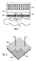
- the gamma cameras used are for the most Anger type camera. Such a camera is schematically represented in FIG.
- the gamma camera has essentially a scintillator crystal 10, equipped with a collimator 12, and a plurality of coupled photomultipliers 14 optically with the scintillator crystal by a transparent material 16.
- This location allows to know also the position of a radioactive zone 18 from which the radiation has been emitted. This is possible in particular thanks to the collimator 12 which, as shown in FIG. 1, eliminates the radiation whose incidence is not substantially normal to the entrance face of the detector.
- Gamma rays that reach the crystal scintillator can, like the radius 20 of the figure 1, be rays that, after leaving the area 18, interact directly with the detector. These rays are part of a phenomenon hereinafter referred to as "radiation direct”.
- the radiation broadcast is likely to cause a localization error of the radioactive zone and contributes to degrade the contrast of the medical image, by adding noise.
- the scattered radiation is characterized by the fact that his energy is less than that of direct radiation.
- the window is narrow, we increase the contrast of the image by limiting the acceptance of the scattered radiation. This, however, is done at detrimental to the number of effective events detected, that is, the number of events that can be used for the forming an image.
- the energy resolution is understood as being the ratio of width to half height of a distribution of the peak of energy around the value of emission energy, on the emission energy.
- Semiconductor detectors such as for example CdTe, CdZnTe, AsGa, PbI 2 directly convert gamma photons into charge carriers.
- the number of charges created is an order of magnitude greater than that obtained in indirect detection with scintillator detectors.
- the resolution of the semiconductor detectors is also improved.
- Figure 2 shows the structure of a detector semiconductor. This one includes a platform 30 equipped with integrated 32 electronic circuits and on which are mounted a plurality of elements of detection 34.
- the detection elements 34 are presented each in the form of a semiconductor block with two opposite parallel faces on which are electrodes.
- An applied electric field on the electrodes allows to migrate the carriers of charges, that is to say the electrons and the holes formed by the interaction of the radiation with the semiconductor.
- the electrodes are also intended to receive the charges and transfer them to the integrated circuits of the platform 30 for the formation of a signal of detection.
- the charge created by gamma radiation is divides into a charge carried by the electrons and in a load carried by the holes.
- the mobility of holes is smaller than that of electrons and their collection efficiency is worse. So, the set of charges created does not contribute in any way equal to the finally delivered detection signal.
- the "trainee” is characteristic of the trapping of loads in the material before their collection.
- the detected events whose energy is less than the energy of the received gamma photons, in because of the phenomenon of trapping, are then confused with those resulting from the broadcast radiation mentioned previously, for which energy is also less than that of direct radiation.
- patent FR-2 738 919 proposes a method and apparatus for operating a signal provided by a detector which allows to get rid of poor transport properties of the holes in the detection elements.
- the collection of charges depends on the structure and crystalline quality of the elements of detection. It also depends on the electric field applied to the electrodes and possible defects present in the material likely to trap the loads.
- the present invention aims to propose a method and an event sorting device for a semiconductor detector, which makes it possible to distinguish signals from events resulting from a scattered radiation and event signals resulting from an incomplete collection of charges.
- Another goal is to propose a method to ensure uniformity correction of detection of the different detection elements of a detector.
- a goal is also to propose such a method correction which makes it possible to retain selectively and preferentially the events resulting from direct radiation.
- an object of the invention is to propose a treatment process likely to be implemented in real time and continuously to allow the image formation instantly and thus facilitate the medical diagnosis.
- biparametric window is meant a window delimited by two characteristic parameters events. It is in this case the amplitude and rise time of the signals corresponding to the events detected.
- the invention is based on the physical principle according to which the signals of the events resulting from the direct radiation but corresponding to the drag of the energy spectrum mentioned in the introduction, have a correlation between their amplitude and their rise time different from that obtained for events resulting from scattered radiation.
- the first phase of the process i.e. the calibration phase can be implemented in the absence of a patient to examine.
- a radiation source corresponding to radioactive material injected into the patient is arranged in face of the detector.
- the activity of this source and the exposure times may be greater than those selected for the examination of a patient. So, during the calibration phase, one can acquire a spectrum on a lot of events.
- a source having preferably a substantially uniform flow having preferably a substantially uniform flow.
- the calibration phase can take place simultaneously for all the detection elements or only for some of the elements.
- the process can be carried out with a mono-energetic source or a source whose spectrum emission has several main peaks at different energies.
- the number of climb time slots and the rise time interval corresponding to each slice can be adjusted according to a fineness of resolution sought.
- the time interval is chosen, for example of the order of 50 ns.
- a continuous set of rise time slices a successive set of slices such as each upper bound of time of rise of a slice corresponds to the lower limit of the next tranche.
- the amplitude range set for each rise time slice can extend so symmetrical or not on both sides of the maximum of amplitude spectrum.
- the width of the interval can to be constant or not.
- a range of amplitude can be set which has a width depending on the amplitude that corresponds to the maximum of the amplitude spectrum of each rise time slice.
- Such a measure reduces the importance granted to events of low amplitude and / or a low rise time. These events are more difficult to separate from those resulting from radiation and thus present a contribution less interesting for the formation of an image.
- This verification operation can be performed quickly and in real time so that it there is almost no delay between detection of an event and the formation of an image holding account of said event.
- phase (a) it is possible during phase (a) to establish a table of couples of ranges of amplitude and time of climb, in which the pairs of amplitude ranges and rise time corresponding to the window biparametric are associated with a logical data of validation of events and in which couples of ranges outside the biparametric window are associated with a logical data of rejection of events, and in step b), we check for each event if amplitude and rise time data correspond to a pair of associated amplitude ranges to a logical data validation or rejection, and rejects events corresponding to a given rejection logic.
- the invention also relates to a method of uniformity correction for a detector of radiation, that is to say a correction tending to standardize the detection efficiency of different detection elements of the detector.
- the modification of the biparametric window acceptance may include the adjustment of at least one acceptance threshold in amplitude and / or in time of rise of events.
- Creating and adjusting a threshold amplitude acceptance and / or rise time allows to take into account for each element of detection, or for each set of elements of detection, more or less important events corresponding to signals that present a small amplitude and / or a low rise time.
- the proposed method eliminates priority events corresponding to weak signals amplitude or low rise time, which bring a most uncertain information contribution for the formation of an image.
- the method makes it possible to accept a more events.
- the method makes it possible take into account additional real events rather than fictitious events.
- the number of setpoint events is per example the average number of events detected by the set of detection elements during the time determined. It can also be the number of events the weaker detected by one of the detection elements.
- the uniformity correction method can be implemented individually for each element of detection or for sets of detection elements comprising a plurality of detection elements.
- the device may comprise in particular a Specific Function Integrated Circuits (ASIC) Card associated with a detection matrix comprising the detection elements.
- ASIC Specific Function Integrated Circuits
- the integrated circuit card can then form the means for measuring the amplitude and rise time.
- the matrix of elements of detection can be associated with first circuits ASIC-type amplifiers and designed for amplification, formatting and multiplexing of signals from detectors.
- first circuits ASIC-type amplifiers At the exit of these first circuits are connected second circuits intended to treat the signals so as to establish for each signal four data that are the coordinates of the X, Y positions of the event detected in a detection plan formed by the detection elements, the data of the amplitude of the signal and the data of its rise time.
- the position coordinates X, Y of the event can simply be given according to the position in the detection plane of the element of detection that delivered the corresponding signal.
- the first and second circuits can be integrated on one or more cards. These cards are associated with a platform receiving elements detection.
- the means of acquisition, determination of a correlation, the means of selection and the sorting means can be realized in the form of a computer program processing data from signal mentioned above.
- the means can also be made in the form of integrated circuits specific.
- the device may comprise, in addition, adjustment means of the biparametric window for to achieve uniform detection efficiency of selected events for each set of detectors.
- adjustment means can also be realized in the form of software.
- the adjustment of the biparametric window allows you to change the selectivity of sorting and thus compensate for the disparities existing between the detection efficiencies of different detection elements or different sets of detection elements.
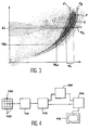
- Figure 3 shows an acquisition spectrum of events for a detection element of a semiconductor detector.
- Events can be characterized by a rise time data and amplitude data of the detection signal. However, since they come from the same element of detection, all the events of this spectrum present therefore the same position data. The following description, however, remains applicable to a set comprising a plurality of detection elements, therefore to events with position data different.
- the spectrum represented is that obtained with a source monoenergetic.
- the spectrum of Figure 3 is acquired during the first phase of the process, that is to say the phase of calibration. The acquisition is continued until obtaining a sufficient number of events for a statistical processing. For example, the spectrum of Figure 3 can relate to 100,000 events.
- Figure 3 shows the events based the amplitude of the corresponding signal, identified in abscissa, and the rise time of the signal, identified in ordered.
- the scales of amplitude and time axes climb are free.
- the scale of the rise times is divided into “slices" each of which has a determined width.
- a single slice is identified with the reference t i .
- Each event detected during the phase of calibration is represented by a dot in the figure. It is assigned to a given climb time slot, depending on the rise time of the signal produced by the detection element in response to this event.
- the amplitude spectrum can be established in also splitting the scale of amplitudes into slices and counting the number of events in each amplitude range. Finally, the spectrum amplitude can be smoothed.
- part of the smoothing curve of the amplitude spectrum is schematically shown in the figure for the rise time slot t i .
- the smoothing curve of the amplitude spectrum is referred to as i .
- This curve is representative of a correlation between the rise time and the amplitude of events resulting from the detection of a direct radiation.
- the curve is referred to as "curve correlation "in the rest of the text.
- a next step consists in determining for each rise time slot an amplitude interval extending on either side of the maximum of the amplitude spectrum.
- the interval associated with the rise time slot t i in FIG. 3 is marked with the reference s i .
- the extension of the interval on both sides of the correlation curve can be adjusted for get selectivity sorting events more or less important, that is to say to reject in a more or less selective events related to the scattered radiation.
- the width of the amplitude range is chosen larger for the amplitudes and the high rise times and is chosen smaller for low amplitudes and low rise times. It can also be adjusted globally depending on the resolution of the element detection.
- the set of amplitude intervals around of the correlation curve, established for all slices of rise time, constitutes, in the example described, the biparametric acceptance window F.
- the window F is delimited by two curves F 1 and F 2 which are formed respectively of the minimum and maximum limit values of the intervals chosen for each rise time slot.
- the different detection elements of a detector do not exhibit the same detection efficiency.
- Changing the size of the window is preferably done by adjusting the window for events corresponding to the lowest values rise time or amplitude.
- the adjustment in the example described is realized by setting an amplitude threshold and / or a threshold of rise time whose value can be changed.
- the thresholds of amplitude and rise times are respectively identified with the Tha and Tht references.
- FIG. Reference 100 in FIG. matrix of semiconductor detection elements 102, arranged in a detection plane. This matrix is comparable to that described with reference to Figure 2.
- the signals delivered by the elements of detection are directed to a first integrated circuit (ASIC) 110.
- ASIC integrated circuit
- This circuit includes signal amplification for each element of detection and channel multiplexing means.
- a second circuit 112 is provided for determine the amplitude and rise time of each signal and to format data corresponding to these quantities, as well as data representing the coordinates of the events.
- the event coordinates are related to the position of the corresponding sensing element in the plane of detection.
- Data is directed to a computer 114 for performing calculations and related processing in the calibration phase and intended to build a image (medical) from the data during the phase review.
- the image is displayed on a screen 116.
- the computer is designed to build, from the data, for each detection element, an acceptance table including the logical values "1" or "0". Values logic "1" are assigned to amplitude-time couples of rising corresponding to the interior of the correlation window, and logical "0" values are assigned to amplitude-rise time outside the window. More precisely, the values logic can be assigned to pairs of ranges amplitude and rise time.
- the tables can also be constructed from the boundaries of the two-parameter window, that is to say, with reference to FIG. 3, from the curves F 1 , F 2 delimiting the window and threshold values Tha, Tht.
- the acceptance tables are stored in a memory indicated with reference 120 in FIG. 4.
- circuits 110 and 112 always establish the amplitude, rise time and coordinates of events to from the signals of the detection elements.
- the data is used to query in real time the acceptance table of the element of corresponding detection and to read the logical value associated with the amplitude-rise time torque.
- the interrogation of the acceptance tables is performed in real time by direct addressing of the concerned table in the memory 120 thanks to the data contained in the output signal of 112.
- Tha and Tht thresholds can be modified also be performed by the computer 114 according to the described above, to make the efficiency detection of the different detection elements more uniform.
Landscapes
- Physics & Mathematics (AREA)
- Health & Medical Sciences (AREA)
- Life Sciences & Earth Sciences (AREA)
- General Physics & Mathematics (AREA)
- High Energy & Nuclear Physics (AREA)
- Molecular Biology (AREA)
- Spectroscopy & Molecular Physics (AREA)
- Nuclear Medicine (AREA)
- Measurement Of Radiation (AREA)
Claims (20)
- Verfahren zur Klassfizierung von Signalen von Detektionsereignissen eines wenigstens ein Halbleiter-Detektionselement umfassenden Gammastrahlungsdetektors, bei dem:a) während einer Kalibrierungsphase:man für jedes Ereignissignal eine Amplitudengröße und eine Signalaufsteigzeitgröße ermittelt,man für wenigstens eine wenigstens ein Detektionselement enthaltende Einheit ein biparametrisches Detektionsspektrum von Ereignissen mit Amplituden- und Aufsteigzeitgrößen erfasst,man für jedes Spektrum wenigstens ein biparametrisches Akzeptanzfenster (F) ermittelt, das jeweils einer für eine Strahlungsenergie charakteristischen Amplitude-Aufsteigzeit-Korrelation entspricht, undb) während einer Prüfphase:man in Echtzeit für jedes detektierte Ereignissignal jeder Detektionselemente-Einheit ein Amplituden- und Aufsteigzeitgrößen-Paar ermittelt,man in Echtzeit eine Klassifizierung der Ereignisse durchführt, indem die Signale selektiert werden, deren Amplituden- und Aufsteigzeitgrößen sich innerhalb des biparametrischen Fensters der entsprechenden Detektionselemente-Einheit befinden, und die Signale ausgeschieden werden, deren Amplituden- und Aufsteigzeitgrößen sich außerhalb dieses biparametrischen Fensters befinden.
- Klassifizierungsverfahren nach Anspruch 1, bei dem - in Schritt a):man eine kontinuierliche Menge von Aufsteigzeitgruppen (ti) definiert,man jedes Ereignis in Abhängigkeit von seiner Aufsteigzeitgröße einer Aufsteigzeitgruppe zuteilt,man für jede Aufsteigzeitgruppe ein Amplitudenspektrum mit den Amplitudengrößen der Ereignisse ermittelt, deren Aufsteigzeit in dieser Aufsteigzeitgruppe enthalten ist,man für jede Aufsteigzeitgruppe ein Maximum des Amplitudenspektrums bestimmt,man für jede Aufsteigzeitgruppe ein Amplitudenintervall (si) festlegt, das sich beiderseits des genannten Maximums erstreckt.
- Verfahren nach Anspruch 2, bei dem man vor der Bestimmung des Maximums jedes Amplitudenspektrums eine Glättung dieses Spektrums durchführt.
- Verfahren nach Anspruch 2, bei dem das Amplitudenintervall (si) sich symmetrisch beiderseits des genannten Maximums erstreckt.
- Verfahren nach Anspruch 2, bei dem das Amplitudenintervall eine Breite aufweist, die abhängig ist von der Amplitude, die dem Maximum des Amplitudenspektrums jeder Aufsteigzeitgruppe entspricht.
- Verfahren nach Anspruch 2, bei dem man während der Prüfphase für jedes Ereignis verifiziert, ob die Amplitudengröße in dem Amplitudenintervall enthalten ist, das der Aufsteigzeitgruppe zugeordnet ist, die seiner Aufsteigzeit entspricht.
- Verfahren nach Anspruch 1, bei dem:während der Phase a) - man eine Tabelle mit Amplituden- und Aufsteigzeitbereichs-Paaren erstellt und abspeichert, in der die dem biparametrischen Fenster entsprechenden Amplituden- und Aufsteigzeitbereichs-Paare einer logischen Validationsgröße der Ereignisse zugeordnet werden, und in der die Bereichpaare außerhalb des biparametrischen Fensters einer logischen Ausscheidungsgröße der Ereignisse zugeordnet sind, undwährend des Schritts b) - man bei jedem Ereignis verifiziert, ob die Amplituden- und Aufsteigzeitgrößen einem abgespeicherten, einer logischen Validations- oder Ausscheidungsgröße zugeordneten Amplituden- und Aufsteigzeitbereichs-Paar entsprechen, und man die einer logischen Ausscheidungsgröße entsprechenden Ereignisse ausscheidet.
- Verfahren nach einem der vorangehenden Ansprüche, bei dem jede Detektionselemente-Einheit ein einziges Detektionselement umfasst.
- Gleichmäßigkeitskorrektur-Verfahren für einen mit wenigstens einem Halbleiter-Detektionselement ausgestatteten Detektor, wobei dieses Verfahren eine Echtzeit-Klassifizierung der Signale von Ereignissen nach Anspruch 1 umfasst, und außerdem während der Kalibrierungsphase umfasst:das Zählen der Anzahl detektierter Ereignisse für jede Detektionselemente-Einheit, unddas Modifizieren des biparametrischen Fensters, um eine Selektivität der Klassierung für wenigstens eine Detektionselemente-Einheit zu erhöhen, die eine größere Detektionseffizienz aufweist, und/oder um diese Selektivität für wenigstens eine Detektionselemente-Einheit zu verringern, die eine kleinere Detektionseffizienz aufweist.
- Verfahren nach Anspruch 9, bei dem das Modifizieren des biparametrischen Akzeptanzfensters das Justieren wenigstens einer Akzeptanzschwelle (Tha, Tht) der Amplitude undloder Aufsteigzeit der Ereignisse umfasst.
- Verfahren nach Anspruch 9, bei dem man die Anzahl der durch eine Detektionselemente-Einheit innerhalb einer festgelegten Zeit detektierten Ereignisse vergleicht mit einer Einstellgröße der Anzahl von Ereignissen, oder Ereignismengen-Einstellgröße, und in der man jeweils die Selektivität der Klassifizierung erhöht oder verringert, wenn die Anzahl detektierter Ereignisse größer beziehungsweise kleiner ist als diese Ereignismengen-Einstellgröße.
- Verfahren nach Anspruch 11, bei dem die Ereignismengen-Einstellgröße einer durchschnittlichen durch die Gesamtheit der Detektionselemente innerhalb der festgelegten Zeit detektierten Anzahl von Ereignissen entspricht.
- Verfahren nach Anspruch 11, bei dem die Ereignismengen-Einstellgröße einer kleinsten durch eines der Detektionselemente detektierten Ereignismenge entspricht.
- Verfahren nach einem der Ansprüche 9 bis 13, bei dem jede Detektionselemente-Einheit ein einziges Detektionselement umfasst.
- Echtzeit-Klassfizierungsvorrichtung von Signalen von Detektionsereignissen, die von einer Vielzahl von Halbleiter-Detektionselementen stammen, umfassend:Einrichtungen (110, 112), um für jedes Signal eine Signal-Amplitudengröße und eine Aufsteigzeitgröße des Signals zu messen,Datenerfassungseinrichtungen, fähig in einer Kalibrierungsphase für wenigstens eine Detektionselemente-Einheit ein biparametrisches Spektrum von Amplituden- und Aufsteigzeitgrößen zu speichern,Einrichtungen, um für jede Detektionselemente-Einheit wenigstens eine Korrelation zwischen den Amplituden- und Aufsteigzeitgrößen zu ermitteln bzw. festzulegen,Einrichtungen zum Selektieren eines biparametrischen Akzeptanzfensters in dem Spektrum,einen Speicher (120), um für jede Detektionselemente-Einheit wenigstens ein dem biparametrischen Akzeptanzfenster entsprechendes Amplituden- und Aufsteigzeitbereichs-Paar abzuspeichern, undKlassfizierungseinrichtungen der Ereignisse, fähig für jede Detektionselemente-Einheit die für jedes Detektionssignal in einer Prüfphase gemessenen Amplituden- und Aufsteigzeitgrößen zu vergleichen mit den abgespeicherten Größenbereichspaaren und die Ereignisse zu selektieren, deren Größen diesen abgespeicherten Bereichspaaren entsprechen.
- Vorrichtung nach Anspruch 15 mit wenigstens einer Karte (110, 112) mit integrierten Schaltungen mit spezifischer Funktion (ASIC), einer Detektionsmatrix (100) zugeordnet, welche die Detektionselemente (102) umfasst und die Einrichtungen zum Messen der Amplitude und der Aufsteigzeit bildet.
- Vorrichtung nach Anspruch 15, bei der die Vorrichtung einen Computer (114) umfasst, der in Programmform die Mittel der Erfassung, der Ermittlung bzw. Festlegung einer Korrelation, die Selektionsmittel und die Klassifizierungsmittel enthält.
- Vorrichtung nach einem der Ansprüche 15 bis 17, die außerdem Einrichtungen zur Einstellung des parametrischen Fensters umfasst, um eine gleichmäßige Detektionseffizienz der für jede Detektoreneinheit selektierten Ereignisse zu erlangen.
- Vorrichtung nach einem der Ansprüche 15 bis 18, bei der jede Detektionselemente-Einheit ein einziges Detektionselement umfasst.
- Gamma-Kamera, ausgerüstet mit einer Vorrichtung nach Anspruch 15.
Applications Claiming Priority (2)
| Application Number | Priority Date | Filing Date | Title |
|---|---|---|---|
| FR9902774 | 1999-03-05 | ||
| FR9902774A FR2790560B1 (fr) | 1999-03-05 | 1999-03-05 | Procede et dispositif de tri en temps reel d'evenements de detection d'un detecteur de rayonnements gamma et de correction d'uniformite d'elements de detection du detecteur |
Publications (2)
| Publication Number | Publication Date |
|---|---|
| EP1037070A1 EP1037070A1 (de) | 2000-09-20 |
| EP1037070B1 true EP1037070B1 (de) | 2004-05-19 |
Family
ID=9542879
Family Applications (1)
| Application Number | Title | Priority Date | Filing Date |
|---|---|---|---|
| EP00400565A Expired - Lifetime EP1037070B1 (de) | 1999-03-05 | 2000-03-02 | Verfahren und Vorrichtung zur Klassifizierung von Ereignissen eines Gammastrahlungsdetektors in Echtzeit |
Country Status (5)
| Country | Link |
|---|---|
| US (1) | US6329651B1 (de) |
| EP (1) | EP1037070B1 (de) |
| JP (1) | JP2000258536A (de) |
| DE (1) | DE60010782T2 (de) |
| FR (1) | FR2790560B1 (de) |
Families Citing this family (15)
| Publication number | Priority date | Publication date | Assignee | Title |
|---|---|---|---|---|
| WO2005000120A2 (en) * | 2003-06-27 | 2005-01-06 | Koninklijke Philips Electronics N.V. | Pmt signal correlation filter |
| US7518102B2 (en) * | 2003-10-27 | 2009-04-14 | Koninklijke Philips Electronics N.V. | Calibration method and apparatus for pixilated solid state detector |
| FR2869692B1 (fr) | 2004-05-03 | 2006-06-23 | Commissariat Energie Atomique | Procede de correction des spectres bi-parametriques |
| FR2872921B1 (fr) * | 2004-07-09 | 2006-09-15 | Commissariat Energie Atomique | Dispositif et procede de mesure de l'energie et de la position d'une particule incidente dans un detecteur |
| FR2887994B1 (fr) | 2005-07-01 | 2008-05-16 | Commissariat Energie Atomique | Procede pour optimiser les performances d'un detecteur a semi-conducteur |
| JP4670704B2 (ja) * | 2006-03-31 | 2011-04-13 | 株式会社日立製作所 | エネルギー較正方法,エネルギー関心領域の設定方法、放射線検出装置及び核医学診断装置 |
| JP2010507090A (ja) | 2006-10-20 | 2010-03-04 | コミサリア、ア、レネルジ、アトミク−セーエーアー | 検出器における相互作用深度を用いるガンマカメラ |
| US9171344B2 (en) | 2007-10-30 | 2015-10-27 | Onemednet Corporation | Methods, systems, and devices for managing medical images and records |
| US8065166B2 (en) | 2007-10-30 | 2011-11-22 | Onemednet Corporation | Methods, systems, and devices for managing medical images and records |
| US9760677B2 (en) | 2009-04-29 | 2017-09-12 | Onemednet Corporation | Methods, systems, and devices for managing medical images and records |
| FR2950979B1 (fr) | 2009-10-07 | 2012-12-07 | Commissariat Energie Atomique | Procede de traitement de donnees issues d'un detecteur de rayonnements ionisants |
| GB201019521D0 (en) | 2010-11-18 | 2010-12-29 | Durham Scient Crystals Ltd | Radiation detection |
| FR3017962B1 (fr) | 2014-02-27 | 2016-04-01 | Commissariat Energie Atomique | Outil de detection de rayonnement photonique particulierement adapte a des rayonnements a fort flux |
| WO2015128905A1 (ja) * | 2014-02-28 | 2015-09-03 | 株式会社ANSeeN | 波形弁別装置、波形弁別方法及び波形弁別プログラム |
| EP2980540A1 (de) * | 2014-08-01 | 2016-02-03 | VEGA Grieshaber KG | Signalabtastung bei einem radiometrischen Messsystem |
Family Cites Families (4)
| Publication number | Priority date | Publication date | Assignee | Title |
|---|---|---|---|---|
| DE3003909C2 (de) * | 1980-02-02 | 1987-01-22 | Kernforschungszentrum Karlsruhe Gmbh, 7500 Karlsruhe | Verfahren zur gleichzeitigen Messung von a- und ß-Teilchen und Detektoreinrichtung zur Durchführung des Verfahrens |
| US4899054A (en) * | 1988-01-19 | 1990-02-06 | General Electric Company | Gamma camera with image uniformity by energy correction offsets |
| FR2738693B1 (fr) * | 1995-09-12 | 1997-10-10 | Commissariat Energie Atomique | Systeme de traitement d'impulsions provenant de l'interaction d'une particule gamma avec un detecteur de rayonnement cdte |
| FR2738919B1 (fr) * | 1995-09-15 | 1997-10-17 | Commissariat Energie Atomique | Procede et dispositif pour la correction de mesure spectrometrique dans le domaine de la detection de photons gamma |
-
1999
- 1999-03-05 FR FR9902774A patent/FR2790560B1/fr not_active Expired - Fee Related
-
2000
- 2000-03-01 US US09/516,807 patent/US6329651B1/en not_active Expired - Lifetime
- 2000-03-01 JP JP2000056347A patent/JP2000258536A/ja active Pending
- 2000-03-02 DE DE60010782T patent/DE60010782T2/de not_active Expired - Lifetime
- 2000-03-02 EP EP00400565A patent/EP1037070B1/de not_active Expired - Lifetime
Also Published As
| Publication number | Publication date |
|---|---|
| EP1037070A1 (de) | 2000-09-20 |
| US6329651B1 (en) | 2001-12-11 |
| FR2790560A1 (fr) | 2000-09-08 |
| DE60010782D1 (de) | 2004-06-24 |
| DE60010782T2 (de) | 2005-06-02 |
| FR2790560B1 (fr) | 2001-04-13 |
| JP2000258536A (ja) | 2000-09-22 |
Similar Documents
| Publication | Publication Date | Title |
|---|---|---|
| EP1037070B1 (de) | Verfahren und Vorrichtung zur Klassifizierung von Ereignissen eines Gammastrahlungsdetektors in Echtzeit | |
| EP0701703B1 (de) | Verfahren und vorrichtung zur erkennung von bestimmten materialien in der zusammensetzung eines gegenstands | |
| EP1233700B1 (de) | Verfahren zur anwendung eines knochendichtemessungssystems mittels röntgenstrahlung bei zwei energien | |
| EP0817472B1 (de) | Verfahren und Vorrichtung zur Aufnahme von Röntgen- und Gammastrahlen-Bildern mit Optimierung der Belichtungszeit | |
| EP2035861B1 (de) | Einrichtung zum lokalisieren und abbilden von gamma- oder röntgenstrahlungsquellen | |
| EP2606817A1 (de) | System zur Wiederherstellung der optischen Eigenschaften eines Diffusionsmediums, das eine pulsierende Strahlungsquelle und mindestens zwei Detektoren unterschiedlichen Typs umfasst, und entsprechendes Wiederherstellungsverfahren | |
| EP0470909B1 (de) | Kernstrahlungsdetektor, insbesondere der Gamma-Kamera-Art unter Verwendung von Dekonvolutionsfiltern | |
| EP1852717A1 (de) | Verfahren zur Schätzung der Streustrahlung in einem zweidimensionalen Detektor | |
| FR2663127A1 (fr) | Images d'appareil radiographique a rayons gamma exemptes d'effet compton. | |
| EP1006719A1 (de) | Verfahren zur Korrektur von Bildartefakten in einem Röntgenstrahlen- oder Gammastrahlendetektor | |
| EP2145208B1 (de) | Röntgenabbildungsvorrichtung mit einer polychromatischen quelle | |
| EP3143429B1 (de) | Verfahren zur verbesserung der energieauflösung von gammastrahlenszintillationsdetektoren, entsprechendes system, komponente und anwendung | |
| CA2163884C (fr) | Procede et dispositif pour la reconnaissance de materiaux determines dans la composition d'un objet | |
| FR2740561A1 (fr) | Methode pour evaluer la variation d'intensite d'un rayonnement polychromatique ayant un spectre de frequence connu, apres traversee d'un corps absorbant | |
| EP0295986A1 (de) | Vorrichtung zur Kern-Strahlungslokalisierung und Strahlungsbilderzeugung | |
| FR2816155A1 (fr) | Procede et dispositif de qualification de detecteurs d'image en fonction de leurs mauvais pixels | |
| EP1058128B1 (de) | Verfahren und Vorrichtung zur Unterscheidung von Impulsen von Halbleiter-Strahlungsdetektoren | |
| FR3013125A1 (fr) | Procede pour ameliorer la resolution en energie de detecteurs de rayons gamma a scintillation, systeme, composant et application associes | |
| WO2005114257A1 (fr) | Procede de correction des spectres bi-parametriques | |
| EP3851837A1 (de) | Verfahren zur bestimmung einer funktion der spektralen empfindlichkeit eines röntgen- oder gammastrahlenmesssystems | |
| EP2981213A1 (de) | Verfahren und system zur kennzeichnung eines knochengewebes | |
| WO2015011344A1 (fr) | Procédé de calcul de position d'interaction d'un photon gamma avec un cristal scintillatuer, dispositif et système de tep mettant en œuvre le procédé | |
| FR2838852A1 (fr) | Procede de correction du rayonnement diffuse de photons x dans un dispositif de radiographie comportant des lames de collimation | |
| EP0366528A1 (de) | Verfahren und Anordnung zum Eichen eines Röntgen-Abtasters mittels mindestens einem Eichkörper | |
| BE866703A (fr) | Formation d'image |
Legal Events
| Date | Code | Title | Description |
|---|---|---|---|
| PUAI | Public reference made under article 153(3) epc to a published international application that has entered the european phase |
Free format text: ORIGINAL CODE: 0009012 |
|
| AK | Designated contracting states |
Kind code of ref document: A1 Designated state(s): DE GB IT |
|
| AX | Request for extension of the european patent |
Free format text: AL;LT;LV;MK;RO;SI |
|
| 17P | Request for examination filed |
Effective date: 20010224 |
|
| AKX | Designation fees paid |
Free format text: DE GB IT |
|
| GRAP | Despatch of communication of intention to grant a patent |
Free format text: ORIGINAL CODE: EPIDOSNIGR1 |
|
| GRAS | Grant fee paid |
Free format text: ORIGINAL CODE: EPIDOSNIGR3 |
|
| GRAA | (expected) grant |
Free format text: ORIGINAL CODE: 0009210 |
|
| AK | Designated contracting states |
Kind code of ref document: B1 Designated state(s): DE GB IT |
|
| REG | Reference to a national code |
Ref country code: GB Ref legal event code: FG4D Free format text: NOT ENGLISH |
|
| REF | Corresponds to: |
Ref document number: 60010782 Country of ref document: DE Date of ref document: 20040624 Kind code of ref document: P |
|
| GBT | Gb: translation of ep patent filed (gb section 77(6)(a)/1977) |
Effective date: 20040820 |
|
| PLBE | No opposition filed within time limit |
Free format text: ORIGINAL CODE: 0009261 |
|
| STAA | Information on the status of an ep patent application or granted ep patent |
Free format text: STATUS: NO OPPOSITION FILED WITHIN TIME LIMIT |
|
| 26N | No opposition filed |
Effective date: 20050222 |
|
| PGFP | Annual fee paid to national office [announced via postgrant information from national office to epo] |
Ref country code: DE Payment date: 20140311 Year of fee payment: 15 |
|
| PGFP | Annual fee paid to national office [announced via postgrant information from national office to epo] |
Ref country code: IT Payment date: 20140314 Year of fee payment: 15 |
|
| PGFP | Annual fee paid to national office [announced via postgrant information from national office to epo] |
Ref country code: GB Payment date: 20140317 Year of fee payment: 15 |
|
| REG | Reference to a national code |
Ref country code: DE Ref legal event code: R119 Ref document number: 60010782 Country of ref document: DE |
|
| GBPC | Gb: european patent ceased through non-payment of renewal fee |
Effective date: 20150302 |
|
| PG25 | Lapsed in a contracting state [announced via postgrant information from national office to epo] |
Ref country code: IT Free format text: LAPSE BECAUSE OF NON-PAYMENT OF DUE FEES Effective date: 20150302 |
|
| PG25 | Lapsed in a contracting state [announced via postgrant information from national office to epo] |
Ref country code: DE Free format text: LAPSE BECAUSE OF NON-PAYMENT OF DUE FEES Effective date: 20151001 Ref country code: GB Free format text: LAPSE BECAUSE OF NON-PAYMENT OF DUE FEES Effective date: 20150302 |