EP1037096A2 - Coupleur directionnel et modulateur Mach-Zehnder utilisant un tel coupleur - Google Patents
Coupleur directionnel et modulateur Mach-Zehnder utilisant un tel coupleur Download PDFInfo
- Publication number
- EP1037096A2 EP1037096A2 EP00104605A EP00104605A EP1037096A2 EP 1037096 A2 EP1037096 A2 EP 1037096A2 EP 00104605 A EP00104605 A EP 00104605A EP 00104605 A EP00104605 A EP 00104605A EP 1037096 A2 EP1037096 A2 EP 1037096A2
- Authority
- EP
- European Patent Office
- Prior art keywords
- optical
- waveguides
- coupling region
- coupler
- outputs
- Prior art date
- Legal status (The legal status is an assumption and is not a legal conclusion. Google has not performed a legal analysis and makes no representation as to the accuracy of the status listed.)
- Withdrawn
Links
Images


Classifications
-
- G—PHYSICS
- G02—OPTICS
- G02F—OPTICAL DEVICES OR ARRANGEMENTS FOR THE CONTROL OF LIGHT BY MODIFICATION OF THE OPTICAL PROPERTIES OF THE MEDIA OF THE ELEMENTS INVOLVED THEREIN; NON-LINEAR OPTICS; FREQUENCY-CHANGING OF LIGHT; OPTICAL LOGIC ELEMENTS; OPTICAL ANALOGUE/DIGITAL CONVERTERS
- G02F1/00—Devices or arrangements for the control of the intensity, colour, phase, polarisation or direction of light arriving from an independent light source, e.g. switching, gating or modulating; Non-linear optics
- G02F1/29—Devices or arrangements for the control of the intensity, colour, phase, polarisation or direction of light arriving from an independent light source, e.g. switching, gating or modulating; Non-linear optics for the control of the position or the direction of light beams, i.e. deflection
- G02F1/31—Digital deflection, i.e. optical switching
- G02F1/313—Digital deflection, i.e. optical switching in an optical waveguide structure
- G02F1/3136—Digital deflection, i.e. optical switching in an optical waveguide structure of interferometric switch type
-
- G—PHYSICS
- G02—OPTICS
- G02B—OPTICAL ELEMENTS, SYSTEMS OR APPARATUS
- G02B6/00—Light guides; Structural details of arrangements comprising light guides and other optical elements, e.g. couplings
- G02B6/10—Light guides; Structural details of arrangements comprising light guides and other optical elements, e.g. couplings of the optical waveguide type
- G02B6/12—Light guides; Structural details of arrangements comprising light guides and other optical elements, e.g. couplings of the optical waveguide type of the integrated circuit kind
- G02B6/122—Basic optical elements, e.g. light-guiding paths
- G02B6/125—Bends, branchings or intersections
-
- G—PHYSICS
- G02—OPTICS
- G02F—OPTICAL DEVICES OR ARRANGEMENTS FOR THE CONTROL OF LIGHT BY MODIFICATION OF THE OPTICAL PROPERTIES OF THE MEDIA OF THE ELEMENTS INVOLVED THEREIN; NON-LINEAR OPTICS; FREQUENCY-CHANGING OF LIGHT; OPTICAL LOGIC ELEMENTS; OPTICAL ANALOGUE/DIGITAL CONVERTERS
- G02F1/00—Devices or arrangements for the control of the intensity, colour, phase, polarisation or direction of light arriving from an independent light source, e.g. switching, gating or modulating; Non-linear optics
- G02F1/01—Devices or arrangements for the control of the intensity, colour, phase, polarisation or direction of light arriving from an independent light source, e.g. switching, gating or modulating; Non-linear optics for the control of the intensity, phase, polarisation or colour
- G02F1/21—Devices or arrangements for the control of the intensity, colour, phase, polarisation or direction of light arriving from an independent light source, e.g. switching, gating or modulating; Non-linear optics for the control of the intensity, phase, polarisation or colour by interference
- G02F1/225—Devices or arrangements for the control of the intensity, colour, phase, polarisation or direction of light arriving from an independent light source, e.g. switching, gating or modulating; Non-linear optics for the control of the intensity, phase, polarisation or colour by interference in an optical waveguide structure
-
- G—PHYSICS
- G02—OPTICS
- G02F—OPTICAL DEVICES OR ARRANGEMENTS FOR THE CONTROL OF LIGHT BY MODIFICATION OF THE OPTICAL PROPERTIES OF THE MEDIA OF THE ELEMENTS INVOLVED THEREIN; NON-LINEAR OPTICS; FREQUENCY-CHANGING OF LIGHT; OPTICAL LOGIC ELEMENTS; OPTICAL ANALOGUE/DIGITAL CONVERTERS
- G02F1/00—Devices or arrangements for the control of the intensity, colour, phase, polarisation or direction of light arriving from an independent light source, e.g. switching, gating or modulating; Non-linear optics
- G02F1/01—Devices or arrangements for the control of the intensity, colour, phase, polarisation or direction of light arriving from an independent light source, e.g. switching, gating or modulating; Non-linear optics for the control of the intensity, phase, polarisation or colour
- G02F1/21—Devices or arrangements for the control of the intensity, colour, phase, polarisation or direction of light arriving from an independent light source, e.g. switching, gating or modulating; Non-linear optics for the control of the intensity, phase, polarisation or colour by interference
- G02F1/212—Mach-Zehnder type
-
- G—PHYSICS
- G02—OPTICS
- G02F—OPTICAL DEVICES OR ARRANGEMENTS FOR THE CONTROL OF LIGHT BY MODIFICATION OF THE OPTICAL PROPERTIES OF THE MEDIA OF THE ELEMENTS INVOLVED THEREIN; NON-LINEAR OPTICS; FREQUENCY-CHANGING OF LIGHT; OPTICAL LOGIC ELEMENTS; OPTICAL ANALOGUE/DIGITAL CONVERTERS
- G02F1/00—Devices or arrangements for the control of the intensity, colour, phase, polarisation or direction of light arriving from an independent light source, e.g. switching, gating or modulating; Non-linear optics
- G02F1/29—Devices or arrangements for the control of the intensity, colour, phase, polarisation or direction of light arriving from an independent light source, e.g. switching, gating or modulating; Non-linear optics for the control of the position or the direction of light beams, i.e. deflection
- G02F1/31—Digital deflection, i.e. optical switching
- G02F1/313—Digital deflection, i.e. optical switching in an optical waveguide structure
- G02F1/3132—Digital deflection, i.e. optical switching in an optical waveguide structure of directional coupler type
Definitions
- the present invention relates to a dual output optical modulator, a method of modulating an optical signal, and an optical emitter with external modulation and a directional coupler.
- the present invention also relates to a CATV system comprising a dual output optical modulator.
- the distribution of television signals in CATV (community antenna television) systems can be carried out by means of optical fibres.
- the optical signal can be modulated in a direct way, by acting on the optical source, normally a laser, or in an indirect way, by means of an optical modulator.
- An optical modulator which can be used for the amplitude modulation of an optical signal, with a modulating signal at radio frequency (RF) having very high frequencies (such as the carriers of television channels, which conventionally range from 40 to 860 MHz), consists, for example, of a device based on an interferometer of the Mach-Zehnder type, constructed on lithium niobate (LiNbO 3 ).
- CATV transmission requires high degree of linearity and low harmonic distortions.
- the electro-optical characteristic in other words the output optical power as a function of the input radio-frequency voltage, of modulators of the type mentioned is typically non-linear. The modulator must therefore be operated in a linear zone of its response characteristic.
- a radio-frequency modulating signal is applied to an RF electrode of an electro-optical modulator of the Mach-Zehnder interferometer type, and a continuous bias voltage, which determines the operating point of the modulator, is applied to the same electrode or to a second electrode.
- the modulating signal, applied to the RF input consists, for example, of the set of modulated carriers of the television channels to be distributed to the users, e.g., in a number of 40 to 80.
- the characteristic (optical transmission versus applied voltage) of Mach-Zehnder type modulators is described by a raised cosine.
- the maximum linearity point is the inflection point of the characteristic, halfway between maximum and minimum transmission.
- the modulator is therefore biased in that point by an applied voltage V Q , so that the electrical modulating RF signal is transformed into an optical modulated signal with minimum second harmonic distortion.
- the value of the biasing point voltage V Q is not constant, but varies with time, for example as a result of the accumulation of static charges in the LiNbO 3 , and also with temperature.
- CSO Composite Second Order
- depth of modulation which is not too great for the modulating signals, for example approximately 3.5% or 4% per channel, in order to operate as near as possible to the linear portion of the characteristic (the term "depth of modulation" denoting the maximum value, expressed as a percentage, of the modulation index ⁇ ).
- a method to reduce the residual distortions, and in particular the third-order distortions consists in pre-distorting the modulating signals by means of non-linear elements, so that the pre-distortion is compensated by the subsequent distortion introduced by the modulator. Further details on this method are described, for example, in the article by M. Nazarathy et al., "Progress in Externally Modulated AM CATV Transmission Systems", published in the Journal of Lightwave Technology, vol. 11, No. 1,01/93, pp. 82-104.
- CATV systems it is particularly advantageous to have the television signals available in a plurality of optical cables for more efficient distribution to the users.
- the Y junction at the end of the Mach-Zehnder can be replaced by a directional coupler, where the phase modulation of light achieved in the two arms by electro-optic effect or in another known way is converted into amplitude modulation by means of evanescent coupling or bimodal interference.
- the two optical outputs will ideally be complementary, that is a minimum transmission in the first output will coincide with a maximum transmission of the second output, and the bias point will be common for the two. In the bias point the two outputs will also have the same power, thus avoiding the above mentioned 3 dB loss.
- US Patent 5,253,309 describes an optical transmission system which makes use of a modulator of the Mach-Zehnder type with a double output.
- the two complementary outputs of the modulator are applied to two optical transmission fibres, and at the receiving end of the optical signal transmission line these fibres are connected to a balanced receiver, which, in order to combine the two received signals, subtracts one from another by means of a differential amplifier.
- the two outputs of a Mach Zehnder modulator may not be precisely complementary but there may be a phase difference (relative phase delay) between the two modulated signals. Moreover, If one of the modulator outputs is locked in the bias point by an appropriate bias voltage V Q , the other output will not operate in a linear condition. It is to be noted that the two outputs cannot be independently set in the respective bias point, because their operating points are linked together.
- EP patent application 98122483.5 A method for reducing distortions in a dual output Mach Zehnder modulator is described in EP patent application 98122483.5 to the name of the Applicant.
- V Q bias voltage
- the amplitude of these distortions is not identical for both outputs.
- both outputs of dual output modulator can be kept under control in order to suitably bias the modulator and reduce the amplitude of distortions to a minimum and to compensate the variations of the operating point.
- phase delay ⁇ between the two outputs can be in the order of less than one degree or, in some cases, in the order of a few degrees.
- a phase delay greater than 0.6° between the two outputs is undesirable in dual output modulators, because it may give rise to unacceptable distortions (greater than -65 dBc) in transmission of analog signals, such as in CATV transmission.
- the above phase delay limit value is associated with a bias point set at or around half-way between the inflection points of the characteristics for the two outputs, as disclosed in above mentioned EP98122483.5.
- Applicant has faced the problem of designing a dual output modulator having stable operating characteristics with respect to random variations in the manufacturing process.
- Applicant has faced the problem of designing a dual output modulator having a predictable and low value of the relative phase delay ⁇ between the two outputs, independent of manufacturing induced fluctuations.
- US 5,563,970 discloses an optical directional coupler filter having at least two guides, an input guide and a coupled guide.
- the spacing between the guides and hence the interactive strength is tailored so as to provide ultralow sidelobe levels at a narrow spectral bandwidth.
- US 5,165,001 relates to optical branching devices with various values of a branching ratio or a coupling ratio, such as 50%, 20% or several %, and faces the task of providing a branching device with a coupling ratio which is less dependent on wavelength in a wide range of wavelengths.
- the patent discloses a guided-wave optical branching device having optical waveguides disposed on a substrate.
- the waveguides are partially arranged to be close to each other to form a tapered directional coupler in which the waveguides are point symmetrical or line symmetrical. Alternatively, the waveguides are neither line symmetrical nor point symmetrical.
- the tapered directional coupler reduces the wavelength dependence of the coupling ratio of the output power derived from the branching device.
- Applicant has found that the maximum possible relative phase delay in a 3 dB directional coupler for use in coherent mixing of optical signal can be reduced by a strong coupling region of reduced length, so that the desired 3 dB coupling is obtained in a shorter length, corresponding to a lower loss.
- Applicant has designed a modified coupler wherein a reduced length of the strong coupling region and matching of the 3 dB coupling condition is achieved by tailoring the distance and, in particular, the minimum distance between waveguides in the coupling region. This is achieved while leaving angles and curvature radiuses (if bends are used) unchanged.
- Applicant has found that using the above designed coupler at the output of a dual output Mach Zehnder modulator results in a modulator with stable and predictably low relative phase delay between its two outputs. Furthermore, higher yields are achieved in the manufacturing process of the modulator without changes in the process technology.
- Applicant has further determined that the relative phase delay in a coupler used to mix an information bearing signal and a local oscillator is advantageously reduced by reducing the losses in a strong coupling region of the coupler, and that use of the invention coupler in a coherent optical receiver allows to mix signal and local oscillator with low IF signal degradation.
- the invention also has to do with a coherent receiver comprising the invention directional coupler.
- the present invention relates to an analog optical transmission system, comprising:
- At least one optical amplifier (205, 210) is coupled along at least one of the fibre lines, and/or at least a distribution station (240, 250) with one input and a plurality of outputs is coupled to at least one of the fibre lines.
- the present invention relates to a dual output electro-optical modulator (100) for modulating an optical signal by an electrical signal (285), comprising a Mach-Zehnder interferometer with an input path (102), two arms (103, 104) and a directional coupler (105), wherein the directional coupler comprises two waveguides on a planar substrate (101) defining two inputs, two outputs and a coupling region between the inputs and the outputs where the waveguides are in close proximity to each other so as to cause coupling between them, characterised in that the coupling region of the directional coupler comprises a strong coupling region and in that the length of parallel sections of optical waveguides in the coupling region is less than 35% of the length of the strong coupling region.
- said input path and said two arms are optical waveguides on said planar substrate.
- the modulator comprises a dielectric buffer layer at least partly covering said planar substrate, and at least one ground electrode (113, 114) for coupling to a reference voltage.
- the modulator comprises an RF electrode (108) for modulating the relative phase between said two arms, and an bias electrode (109) for setting the operating point of the modulator.
- the modulator comprises an electrode (111) for the phase modulation of said optical signal.
- the present invention relates to an optical apparatus comprising at least an optical source for generating two mutually coherent signals and a planar optics coupler (105) for coherently mixing said optical signals, wherein the coupler comprises two optical waveguides (103, 104) formed on a planar substrate defining two inputs, two outputs and a coupling region between the inputs and the outputs where the waveguides are in close proximity to each other so as to cause coupling between them, characterised in that the coupling region comprises a strong coupling region and in that the length of parallel sections of optical waveguides in the coupling region is less than 35% of the length of the strong coupling region.
- the relative phase of the two optical signals changes with time.
- the coupler has a splitting ratio between 44% and 56%, more preferably it has a 50% splitting ratio.
- the coupler has a relative phase delay lower than 0.6°, more preferably lower than 0.3°.
- the present invention relates to a coherent optical receiver for receiving a coherent information bearing signal comprising a local oscillator (310), an optical coupler (105) with two inputs and two outputs and two photodetectors coupled at respective coupler outputs, the coupler comprising two optical waveguides formed on a planar substrate defining two inputs, two outputs and a coupling region between the inputs and the outputs wherein the waveguides are in dose proximity to each other so as to cause coupling between them, characterised in that the coupling region comprises a strong coupling region and in that the length of parallel sections of optical waveguides in the coupling region is less than 35% of the length of the strong coupling region.
- the present invention relates to a method for reducing the relative phase delay in a planar waveguide coupler comprising the steps of:
- said uniform splitting ratio is between 44% and 56%.
- a CATV transmission system is schematically shown in fig. 6.
- the output of a laser source 200 such as a semiconductor laser source, for example a DFB laser, is coupled via a single mode optical fibre 106 to the input of a dual output electro-optical modulator 100, that is described in the following.
- Typical wavelength values for the laser source 200 are, for example, in the range 1540-1560 nm or in the range 1300 - 1320 nm.
- Fibre 106 is preferably a polarisation maintaining fibre.
- a bias voltage 290 is also input to modulator 100 to bring its operating (bias) point in a linear response region.
- An additional electrical input for an SBS suppression signal 280 may be provided on modulator 100.
- an optical signal propagated along an optical fibre may give rise, if the optical power density is high, to the generation of radiation by stimulated Brillouin scattering (SBS).
- SBS stimulated Brillouin scattering
- modulator 100 may provide an electrode for the phase modulation of the signal to be transmitted.
- the power and the frequency of the modulating electrical signal are selected, according to known relations, in such a way as to obtain the requisite widening of the band of the optical signal.
- the two outputs of modulator 100 are coupled each to an optical fibre line 220, 230, provided to transmit the modulated signal to respective distribution stations 240, 250.
- Each of the latter can comprise an optical coupler to split and distribute the optical signal, via respective optical fibre lines 260, 270, to receiving units 265, 275, where the optical signal is converted to electrical signals and sent respective an RF distribution networks or, alternatively, directly to end users.
- Fibre lines 220, 230, 260, 270 are preferably monomodal. Multimode fibres, however, can be advantageously adopted to cover relatively short line sections, e.g., in the range of few km. Multimode fibres, in particular, can be adopted for the signal distribution fibre network (260, 270).
- Optical amplifiers 205, 210 can be provided at one or at each output of modulator 100 to boost the optical signal and increase the transmission distance along fibres 220, 230 and/or to increase the number of receiving units 265, 275 to be reached by the optical signal.
- the skilled in the art, to fulfil the specific needs of a signal distribution network may, according to known techniques, arrange additional optical amplifiers (not shown) along optical fibres 220, 230, 260, 270 and/or at the output of distribution stations 240, 250.
- the schematic distribution network 240, 250, 260, 270, 265, 275 shown in figure 6 can be adapted by the skilled in the art to the specific needs that arise in each practical case, e.g., by selecting an appropriate number and arrangement of distribution stations, optical fibres and receiving units.
- FIG. 1 an optical modulator particularly adapted for use in CATV systems is shown.
- the modulator 100 is made on a planar substrate 101.
- On the substrate surface an interferometric Mach-Zehnder waveguide configuration is formed in a manner convenient to the skilled in the art.
- planar substrate and the waveguides are made in any material convenient to the skilled in the art, for example, in one or a combination of the following material systems: semiconductors of the III-V or II-VI group, Si, glass, silica, polymer, ferroelectric and/or electrooptic materials.
- the substrate is an x-cut lithium niobate crystal and the waveguides are made by titanium diffusion.
- Such waveguide configuration comprises, as shown in fig. 1, an input waveguide 102 at a first end of the substrate 101, a bifurcation 110, such as a Y splitter, and two waveguide arms 103, 104. Arms 103, 104 come close together to form a directional coupler 105 and then separate again to terminate at an end of the substrate.
- the relative distance of waveguides 103, 104 at the substrate end is selected in relation to the technology chosen to couple the waveguide outputs to optical fibres.
- An exemplary value for the waveguide distance is 140 ⁇ m.
- Waveguides 102, 103, 104 are single-mode waveguides at the device operating wavelength.
- waveguide will be used, for simplicity reasons, to refer to a single-mode waveguide.
- a preferable operating wavelength for modulator 100 is in the range 1540-1560 nm.
- the skilled in the art may, according to known techniques, select the device parameters, such as waveguide dimensions and layout, to adapt the herein disclosed modulator for operation in the 1300 - 1320 nm wavelength range.
- a thin dielectric buffer layer of SiO 2 , or another suitable dielectric material, can be used to cover the substrate 101 and waveguides formed therein.
- the thickness of the buffer layer is preferably comprised between 0 and 1 ⁇ m.
- a RF electrode 108 and a bias electrode 109 are laid down on the buffer layer (if present), in the central region of the substrate 101, between the waveguide arms 103, 104.
- the length of the RF electrode is preferably comprised between 30 and 50 mm.
- the length of the bias electrode is preferably comprised between 5 and 15 mm.
- RF electrode 108 is formed on a dielectric layer as above described, while bias electrode 109 is formed directly on the substrate surface, without any intermediate buffer layer.
- This embodiment as disclosed in US 4,871,223, advantageously reduces the drift with time of the operating or bias point of the modulator.
- a single electrode is present for RF and bias.
- a phase modulation electrode 111 is advantageously arranged on the buffer layer (if present) on the side of the input waveguide 102, to modulate the phase of the input optical signal by an SBS suppression signal, as previously explained.
- An alternative embodiment, not shown, has no phase modulating electrode 11 integrated together with the Mach-Zehnder amplitude modulator, resulting in a shorter device.
- Ground electrodes 113 and 114 are also laid down on the substrate 101 and connected to a suitable voltage reference (ground reference).
- RF electrode 108 is advantageously terminated to the ground at an end opposite to the signal input end by a suitable resistive termination 112.
- Input optical fibre 106 and output optical fibres 220, 230 are fixed respectively to the first and to the second end of the substrate 101 in a conventional manner, for example by means of conventional fibre blocks and UV curable adhesives, after aligning with optical waveguides 102, 103, 104.
- a right angle is shown in fig. 1 between the end and side surfaces of the substrate 101, an actual angle of approximately 6° with respect to a line normal to the side surfaces is generally used in practice. This small deviation from a right angle between end and side surfaces avoids backreflections in the optical fibres due to the transition zones between fibres 106, 107, 107' and substrate 101.
- the modulator as described so far is implemented on a planar substrate.
- Other possible embodiments (not shown) for modulator 100 include forming on a planar substrate only coupler 105, or e.g., only interferometer arms 103, 104 and coupler 105.
- the remaining sections of the Mach Zehnder modulator can be made in free-space-propagation (bulk) optics or microoptics, according to known techniques.
- a bulk beam splitter can be used instead of Y junction 110, and the optical beams from the two outputs of the beam splitter can be coupled to the planar substrate section of the device with known coupling techniques.
- the output directional coupler 105 provides interference between light in the two arms. If the arms 103, 104 are of exactly equal optical path length, the optical signals recombine in phase and a maximum of interference is reached. Equal optical powers will be sent in this case to the two outputs of coupler 105. If a phase difference is introduced between the two signals, interference in the coupler will distribute the light intensity unevenly between the coupler outputs.
- the phase difference between the two signals travelling in the arms 103, 104 is introduced by means of a RF signal applied to the RF electrode 108.
- the RF signal modifies the index of refraction in the central region of the substrate 101, in particular in the waveguide arms 103, 104, due to the electro-optical property of the lithium niobate.
- phase velocity matching between the optical and a travelling wave RF signal can be improved by the presence of a dielectric buffer layer, e.g., in SiO 2 .
- the thickness of the buffer layer is advantageously selected, according to known techniques, so as to maximise the above indicated phase velocity matching.
- the modulation of the RF electrical signal is transformed in intensity modulation of the optical signal launched at the two outputs of directional coupler 105, toward the second end of the substrate 101 and then to the output optical fibres 220, 230', with a characteristic response curve described by a raised cosine, for each output.
- the two output signals are ideally complementary, that is a maximum in the response curve of the first output coincides with a minimum in the response curve of the second output.
- the modulator 100 is driven to operate in the maximum linearity point of its characteristic response by means of a signal V Q applied to the bias electrode 109.
- V Q applied to the bias electrode 109.
- the applied bias voltage is common for both the output signals.
- This situation is sketched in fig. 2, which is a graph of output power Pu versus voltage V applied to the RF electrode.
- the first output P1 is in the maximum linearity point; the actual second output P2 r , slightly shifted with respect to the ideal output P2 i , is out of the maximum linearity point by a relative phase delay ⁇ .
- the relative voltage delay ⁇ V (corresponding to a phase delay ⁇ ) is deliberately enhanced for clarity's sake. Applicant has observed that in actual devices ⁇ can be in the order of less than one degree or, in some cases, in the order of a few degrees. In this connection, Applicant has noted that a relative phase delay greater than 0.6° may give rise to unacceptable distortions (greater than -65 dBc).
- the modulator is driven to operate at or around half-way between the two curves of fig. 2 (P1 and P2 r ), as taught in above mentioned EP98122483.5.
- both outputs are slightly out of the maximum linearity point, the maximum deviation from the linearity point for the two outputs is decreased, resulting in a decrease in distortion.
- the relative phase delay ⁇ for a dual output Mach Zehnder modulator can be measured with the experimental setup sketched in fig. 5.
- the signal coming from a laser 200 which can be a DFB laser with a wavelength of 1550 nm, is passed to the modulator 100 and comes out from the two outputs of the same.
- a RF signal from a RF signal generator 500 is also coupled to the modulator 100.
- the RF signal can be for example a triangular ramp at 100 KHz.
- the two outputs of the modulator 100 are connected to two photodiodes 300, 300', in such a way that the modulated signal can be measured by a digital oscilloscope 400, triggered by the RF signal generator 500.
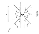
- Coupler 105 comprises optical waveguides 103, 104 formed on a planar optical substrate. It can be advantageously used, for example, in the previously described dual output modulator. Coupler 105 can be subdivided for convenience in five different regions, indicated with reference numbers from 1 to 5 in fig. 3a.
- waveguides 103, 104 converge according to angles ⁇ 1 , ⁇ 2 with respect to a longitudinal direction Y of the substrate.
- waveguides 103, 104 are still in mutual approach, but bent, for example according to arcs of a circle having radiuses of curvature R 1 , R 2 .
- waveguides 103, 104 are parallel and separated by a distance H.
- the term "parallel” is used to indicate waveguides that form an angle of less than 0.2° between them.
- the distance H between the waveguides 103, 104 is to be intended as the minimum distance between the waveguides 103, 104.
- the length of such central region 3, indicated with L p in fig. 3a, is chosen in such a way that if an optical signal is launched in one of the waveguides 103, near half of the optical power is coupled in the other waveguide 104 (3 dB coupling condition). As shown in fig.
- ER extinction ratio
- an ER value higher than 22 dB is preferred.
- Maximum ER is also related to tolerances in the waveguides manufacturing process, in particular to repeatability in the value of the horizontal mode field diameter (HMFD).
- the horizontal mode field diameter (HMFD) is defined as the 1/e 2 width of the field of the single mode propagating in the optical waveguides 103,104 in a direction parallel to the plane of the substrate.
- the HMFD is related to the dimensions of the optical waveguides.
- the HMFD of the optical waveguide is constant along the whole waveguides, including the coupling region.
- waveguides 103, 104 start to diverge according to suitable bends, for example according to arcs of a circle having radiuses of curvature R 3 , R 4 .
- waveguides 103, 104 diverge according to angles ⁇ 3 , ⁇ 4 with respect to a longitudinal direction Y on the substrate.
- Angles ⁇ 1 , ⁇ 2 , ⁇ 3 ⁇ 4 as well as radius of curvature R 1 , R 2 , R 3 , R 4 may have the same value and have to be sufficiently low in order to avoid excess losses: typical values are tenths of degree to few degrees for the angles and millimetres to tens of mm for the radiuses of curvature.
- converge and diverge is referred herein to the direction of travelling of the optical signals in the coupler, that is from left to right in figure 3a. It is observed, however, that the directional coupler of the invention is symmetrical, and is not limited to a specific travelling direction for the optical signals.
- an evanescent directional coupler is achieved by smoothly decreasing the distance between two waveguides until a value which gives an appreciable coupling.
- the coupler comprises further a parallel waveguide section, where usually the major part of the coupling takes place, then the distance is again increased to let the waveguides be uncoupled.
- the coupling is measured through a coupling coefficient per unit length k(z).
- the coupling coefficient never becomes zero, but it is considered zero when it is so small that no appreciable coupling takes place within the components typical dimensions (some centimetres of length).
- an optical horizontal mode field diameter of about 10 ⁇ m referring to diffused Titanium waveguides on Lithium Niobate
- waveguides with a relative distance greater than 30 ⁇ m are considered uncoupled.
- a total coupling length can be defined as the length of the region wherein the centre lines of the waveguides have a distance lower than three times the HMFD.
- the integration limits are ⁇ but it is understood that only a limited section is important for the coupling, namely a coupling region having the above defined total coupling length.
- a preferred splitting ratio between 44% and 56% corresponds to 0.88 ⁇ /4 ⁇ C ⁇ 1.12 ⁇ /4.
- a “strong coupling region” is defined as the region around the minimum distance H between the optical waveguides 103, 104 wherein the centre lines of optical waveguides 103, 104 are separated by less than 1.5 horizontal mode field diameters.
- the length of the strong coupling region is indicated as L scr .
- the length L p of the coupling region where the optical waveguides 103,104 are parallel is less than 35% of the total length the strong coupling region (L p ⁇ 0.35 L scr ).
- a series of dual output modulators comprising a directional coupler with parallel waveguides according to the first embodiment of Fig. 3a was made by Applicant.
- the modulators were made on an X-cut, 50 mm long, 4 mm wide, 1 mm thick lithium niobate chip.
- Optical waveguides in the configuration of fig. 1 were made on the surface of the chip by titanium diffusion.
- a 0.5 ⁇ m thick layer of SiO 2 was deposited, followed by deposition of 5 ⁇ m thick gold RF and bias electrodes.
- the lengths of the RF electrode and of the bias electrode were respectively 30 mm and 9 mm. No phase modulator was present.
- angles ⁇ 1 , ⁇ 2 , ⁇ 3 , ⁇ 4 were all 0.5°; radiuses of curvature R 1 , R 2 , R 3 , R 4 of bends were 50 mm; the minimum distance H between the centre line of the waveguides was 12 ⁇ m.
- the modulators were made with different values of length L p for the parallel waveguides region 3 of fig. 3a.
- the results are reported, in terms of length of the strong coupling region L scr , corresponding value L p /L scr , extinction ratio ER and relative phase delay ⁇ obtained.
- a directional coupler according to a second embodiment is shown in fig. 3b. Same reference numbers represent the same or similar elements with respect to fig. 3a.
- the coupler 105 is formed by waveguides 103, 104 and can be subdivided for convenience in three different regions, indicated with reference numbers 1, 3', 5 in fig. 3b.
- waveguides 103, 104 converge according to angles ⁇ 1 , ⁇ 2 , with respect to a longitudinal direction Y of the substrate.
- waveguides 103, 104 diverge according to angles ⁇ 3 , ⁇ 4 , with respect to a longitudinal direction Y of the substrate.
- waveguides 103, 104 are bent in such a way that they converge, reach a minimum relative distance H' and start to diverge from each other again.
- the waveguide bend is, for example, according to arcs of a circle having radiuses of curvature R 1 , R 2 , R 3 , R 4 as shown in fig. 3b.
- the optical waveguides 103, 104 are substantially not parallel (within ⁇ 0.1°) and the length L p of the region of parallel waveguides in this second embodiment is substantially 0.
- the total length of the region 3' is lower than the ensemble of the regions 2, 3, 4 of a directional coupler according to the first embodiment having same values of ⁇ 1 , ⁇ 2 , ⁇ 3 , ⁇ 4 and R 1 , R 2 , R 3 , R 4 .
- mutual approaching of optical waveguides 103, 104 reaches a minimum value H' which is lower than the corresponding value H in the directional coupler of the first embodiment having same values of ⁇ 1 , ⁇ 2 , ⁇ 3 , ⁇ 4 and R 1 , R 2 , R 3 , R 4 .
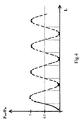
- the total length of the directional coupler is chosen in such a manner that it is the minimum length for which the 3 dB condition is satisfied (referring to fig. 4).
- a series of modulators comprising a directional coupler with any region of parallel waveguides was made by the Applicant. Geometrical dimensions of the chip, waveguides, electrodes, angles and radius of curvature of bends in the directional coupler were the same of example 1.
- the modulators were made with various values of the minimum distance H' between waveguides, in the region indicated with 3' in fig. 3b.
- the length of the strong coupling region L scr was of about 760 ⁇ m for all these modulators.
- the length of the parallel waveguide region L p is in this case substantially 0 for all the modulators of this series.
- H' ( ⁇ m) ER (dB) ⁇ (°) 11.0 -19.17 0.52 10.9 -25.78 0.56 10.8 -33.84 0.05 10.7 -31.54 0.04 10.6 -20.54 0.37 10.5 -20.01 0.31
- a modulator comprising a directional coupler substantially free of a parallel waveguide section is a preferred embodiment of the invention.
- Applicant has developed a simplified model of directional coupler to account for the losses along the coupler waveguides. In the model the losses are assumed to be proportional to the propagation length.
- a computer simulation based on this model has been made, to compare the performances of a conventional coupler and a coupler according to fig. 3b. Geometrical parameters adopted in the simulation are as follows:
- the conventional coupler is assumed to have a design according to fig. 3a, but a relatively long length of the parallel waveguide section 3.
- a distance H 12 ⁇ m between the waveguides is assumed for the conventional coupler.
- L p 500 ⁇ m.
- the difference in length between the two couplers amounts to 270 ⁇ m, to be compared to a total coupling length of 3 mm. This does not correspond to an important reduction in the overall component length, but is nevertheless decisive for the relative delay performance of the coupler.
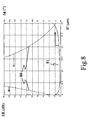
- Fig. 8 reports relative delay 81 (in degrees) and ER values 80 (in dB) versus H' (in ⁇ m) for a coupler according to fig. 3b.
- the result shows that the region of minimum relative phase delay corresponds with the region of maximum ER.
- a choice of the waveguide layout leading to operation in a region of maximum ER is preferred, due to an increased tolerance to manufacturing process variations.
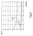
- Fig. 9 is a chart reporting relative delay versus extinction ratio for a conventional coupler (90) and a coupler according to fig. 3b (91). It is apparent that the invention coupler of fig. 3b has superior performances in comparison with the conventional coupler, for example as to the absolute value of relative phase delay. Moreover, the relative phase delay is flatter with respect to the coupling ratio, thus ensuring an increased tolerance with respect to technological process fluctuations.
- the invention coupler may also be used advantageously in a coherent receiver.
- a coherent receiver 390 is schematically shown in fig. 7.
- An optical source 310 (local oscillator) is coupled to one input of an optical coupler 105 according to one of the previously disclosed embodiments.
- An optical transmission signal is generated by a modulated laser source 320 at a distant location and transmitted by an optical fibre 330 to a second input of optical coupler 105.
- coupler 105 The two complementary outputs of coupler 105 are coupled to photodetectors 340, 350.
- the electrical signals from photodetectors 340, 350 are further processed electronically, according to known techniques, to extract the signal modulation information.
- Applicants have determined that by use of the invention directional coupler significantly low loss values in a strong coupling region of the coupler are achieved, and that low phase delay between the coupler output result, so that the signal and local oscillator are effectively mixed with low IF signal degradation.
Landscapes
- Physics & Mathematics (AREA)
- Nonlinear Science (AREA)
- General Physics & Mathematics (AREA)
- Optics & Photonics (AREA)
- Engineering & Computer Science (AREA)
- Microelectronics & Electronic Packaging (AREA)
- Optical Modulation, Optical Deflection, Nonlinear Optics, Optical Demodulation, Optical Logic Elements (AREA)
- Optical Integrated Circuits (AREA)
Priority Applications (1)
| Application Number | Priority Date | Filing Date | Title |
|---|---|---|---|
| EP00104605A EP1037096A3 (fr) | 1999-03-13 | 2000-03-03 | Coupleur directionnel et modulateur Mach-Zehnder utilisant un tel coupleur |
Applications Claiming Priority (3)
| Application Number | Priority Date | Filing Date | Title |
|---|---|---|---|
| EP99105247 | 1999-03-13 | ||
| EP99105247 | 1999-03-13 | ||
| EP00104605A EP1037096A3 (fr) | 1999-03-13 | 2000-03-03 | Coupleur directionnel et modulateur Mach-Zehnder utilisant un tel coupleur |
Publications (2)
| Publication Number | Publication Date |
|---|---|
| EP1037096A2 true EP1037096A2 (fr) | 2000-09-20 |
| EP1037096A3 EP1037096A3 (fr) | 2001-06-27 |
Family
ID=26070632
Family Applications (1)
| Application Number | Title | Priority Date | Filing Date |
|---|---|---|---|
| EP00104605A Withdrawn EP1037096A3 (fr) | 1999-03-13 | 2000-03-03 | Coupleur directionnel et modulateur Mach-Zehnder utilisant un tel coupleur |
Country Status (1)
| Country | Link |
|---|---|
| EP (1) | EP1037096A3 (fr) |
Cited By (10)
| Publication number | Priority date | Publication date | Assignee | Title |
|---|---|---|---|---|
| WO2007144617A1 (fr) * | 2006-06-14 | 2007-12-21 | Filtronic Plc | Modulateur électro-optique accordable |
| CN100399180C (zh) * | 2006-02-17 | 2008-07-02 | 中国科学院上海光学精密机械研究所 | 幅度调制效应补偿装置 |
| EP2458416A1 (fr) * | 2010-11-29 | 2012-05-30 | Octrolix BV | Système optique doté d'une région de couplage symétrique |
| WO2018154309A1 (fr) * | 2017-02-23 | 2018-08-30 | Oxford University Innovation Ltd. | Coupleur de signaux |
| CN109031709A (zh) * | 2018-09-29 | 2018-12-18 | 深圳市芯思杰智慧传感技术有限公司 | 一种设有定向耦合器的光波导相位调制器芯片 |
| WO2024086459A1 (fr) * | 2022-10-19 | 2024-04-25 | Dell Products L.P. | Système de réseau optique ic-trosa |
| US11997436B2 (en) | 2022-04-28 | 2024-05-28 | Dell Products L.P. | IC-TROSA point-to-multipoint optical network system |
| US12126383B2 (en) | 2022-04-28 | 2024-10-22 | Dell Products L.P. | IC-TROSA point-to-multipoint optical network system |
| US12176956B2 (en) | 2022-04-28 | 2024-12-24 | Dell Products L.P. | IC-TROSA optical network system |
| US12176955B2 (en) | 2022-04-28 | 2024-12-24 | Dell Products L.P. | IC-TROSA optical network system |
Family Cites Families (3)
| Publication number | Priority date | Publication date | Assignee | Title |
|---|---|---|---|---|
| US5253309A (en) * | 1989-06-23 | 1993-10-12 | Harmonic Lightwaves, Inc. | Optical distribution of analog and digital signals using optical modulators with complementary outputs |
| GB2239715B (en) * | 1990-01-06 | 1994-04-27 | Plessey Co Plc | Integrated optical device |
| US5563970A (en) * | 1995-02-08 | 1996-10-08 | Northern Telecom Limited | Taper shapes for ultralow sidelobe levels in directional coupler filters |
-
2000
- 2000-03-03 EP EP00104605A patent/EP1037096A3/fr not_active Withdrawn
Cited By (12)
| Publication number | Priority date | Publication date | Assignee | Title |
|---|---|---|---|---|
| CN100399180C (zh) * | 2006-02-17 | 2008-07-02 | 中国科学院上海光学精密机械研究所 | 幅度调制效应补偿装置 |
| WO2007144617A1 (fr) * | 2006-06-14 | 2007-12-21 | Filtronic Plc | Modulateur électro-optique accordable |
| US8244076B2 (en) | 2006-06-14 | 2012-08-14 | U2T Photonics Uk Limited | Tuneable electro-optic modulator |
| EP2458416A1 (fr) * | 2010-11-29 | 2012-05-30 | Octrolix BV | Système optique doté d'une région de couplage symétrique |
| US8494323B2 (en) | 2010-11-29 | 2013-07-23 | Octrolix Bv | Optical system having a symmetrical coupling region for coupling light between waveguides including an optically resonant element |
| WO2018154309A1 (fr) * | 2017-02-23 | 2018-08-30 | Oxford University Innovation Ltd. | Coupleur de signaux |
| CN109031709A (zh) * | 2018-09-29 | 2018-12-18 | 深圳市芯思杰智慧传感技术有限公司 | 一种设有定向耦合器的光波导相位调制器芯片 |
| US11997436B2 (en) | 2022-04-28 | 2024-05-28 | Dell Products L.P. | IC-TROSA point-to-multipoint optical network system |
| US12126383B2 (en) | 2022-04-28 | 2024-10-22 | Dell Products L.P. | IC-TROSA point-to-multipoint optical network system |
| US12176956B2 (en) | 2022-04-28 | 2024-12-24 | Dell Products L.P. | IC-TROSA optical network system |
| US12176955B2 (en) | 2022-04-28 | 2024-12-24 | Dell Products L.P. | IC-TROSA optical network system |
| WO2024086459A1 (fr) * | 2022-10-19 | 2024-04-25 | Dell Products L.P. | Système de réseau optique ic-trosa |
Also Published As
| Publication number | Publication date |
|---|---|
| EP1037096A3 (fr) | 2001-06-27 |
Similar Documents
| Publication | Publication Date | Title |
|---|---|---|
| US5031235A (en) | Cable system incorporating highly linear optical modulator | |
| Williamson et al. | RF photonics | |
| EP0817988B1 (fr) | Modulateur electro-optique non affecte par la polarisation | |
| EP0728325B1 (fr) | Systeme de modulation optique en cascade a forte linearite | |
| US9250452B1 (en) | Tunable photonic RF circulator for simultaneous transmit and receive | |
| JP2698797B2 (ja) | 光搬送波の外部変調方法とその装置 | |
| US8149492B2 (en) | Optical modulator | |
| US6483953B1 (en) | External optical modulation using non-co-linear compensation networks | |
| US6532315B1 (en) | Variable chirp optical modulator having different length electrodes | |
| CA2080932C (fr) | Generateur de solitons | |
| Wooten et al. | Rapidly tunable narrowband wavelength filter using LiNbO/sub 3/unbalanced Mach-Zehnder interferometers | |
| US6943931B1 (en) | Ultra-high linearized optical modulator | |
| US20180031946A1 (en) | Electro-optic modulator, microwave photonic link including an electro-optic modulator, and method of communicating a signal with an electro-optic modulator | |
| AU709120B2 (en) | Modulated and depolarised optical signal transmission system | |
| US5422966A (en) | Microwave electro-optic mixer | |
| US20210194586A1 (en) | Electro-optic modulator and microwave photonic link including an electro-optic modulator | |
| US20070211984A1 (en) | Optical coupler | |
| Tavlykaev et al. | Highly linear Y-fed directional coupler modulator with low intermodulation distortion | |
| US20020110302A1 (en) | Resonant optical modulators with zero chirp | |
| EP1037096A2 (fr) | Coupleur directionnel et modulateur Mach-Zehnder utilisant un tel coupleur | |
| EP0884627A2 (fr) | Modulateur optique à modulation de fréquence parasite (chirp) contrÔlable et méthode de contrÔle du chirp | |
| US20040114208A1 (en) | Electro-optical modulators and methods of modulating optical signals | |
| US6996345B1 (en) | Linearization of intensity modulators using quadratic electro-optic effect | |
| Anderson et al. | Integrated slow-light enhanced silicon photonic modulators for rf photonic links | |
| US6535653B1 (en) | Variable chirp optical modulator |
Legal Events
| Date | Code | Title | Description |
|---|---|---|---|
| PUAI | Public reference made under article 153(3) epc to a published international application that has entered the european phase |
Free format text: ORIGINAL CODE: 0009012 |
|
| AK | Designated contracting states |
Kind code of ref document: A2 Designated state(s): AT BE CH CY DE DK ES FI FR GB GR IE IT LI LU MC NL PT SE |
|
| AX | Request for extension of the european patent |
Free format text: AL;LT;LV;MK;RO;SI |
|
| RAP1 | Party data changed (applicant data changed or rights of an application transferred) |
Owner name: OPTICAL TECHNOLOGIES ITALIA S.P.A. |
|
| PUAL | Search report despatched |
Free format text: ORIGINAL CODE: 0009013 |
|
| AK | Designated contracting states |
Kind code of ref document: A3 Designated state(s): AT BE CH CY DE DK ES FI FR GB GR IE IT LI LU MC NL PT SE |
|
| AX | Request for extension of the european patent |
Free format text: AL;LT;LV;MK;RO;SI |
|
| RIC1 | Information provided on ipc code assigned before grant |
Free format text: 7G 02B 6/28 A, 7G 02F 1/313 B, 7G 02F 1/35 B |
|
| AKX | Designation fees paid | ||
| REG | Reference to a national code |
Ref country code: DE Ref legal event code: 8566 |
|
| STAA | Information on the status of an ep patent application or granted ep patent |
Free format text: STATUS: THE APPLICATION IS DEEMED TO BE WITHDRAWN |
|
| 18D | Application deemed to be withdrawn |
Effective date: 20011228 |