EP1037116A2 - Procédé de développement d'un précurseur de plaque d'impression lithographique et appareil de développement - Google Patents
Procédé de développement d'un précurseur de plaque d'impression lithographique et appareil de développement Download PDFInfo
- Publication number
- EP1037116A2 EP1037116A2 EP00104489A EP00104489A EP1037116A2 EP 1037116 A2 EP1037116 A2 EP 1037116A2 EP 00104489 A EP00104489 A EP 00104489A EP 00104489 A EP00104489 A EP 00104489A EP 1037116 A2 EP1037116 A2 EP 1037116A2
- Authority
- EP
- European Patent Office
- Prior art keywords
- developer
- development
- developing
- resin composition
- photosensitive
- Prior art date
- Legal status (The legal status is an assumption and is not a legal conclusion. Google has not performed a legal analysis and makes no representation as to the accuracy of the status listed.)
- Withdrawn
Links
- 238000011161 development Methods 0.000 title claims abstract description 380
- 238000012545 processing Methods 0.000 title claims abstract description 172
- 238000007639 printing Methods 0.000 title claims abstract description 160
- 238000000034 method Methods 0.000 title claims abstract description 118
- 239000002243 precursor Substances 0.000 title claims abstract description 54
- 239000000463 material Substances 0.000 claims abstract description 111
- 239000011342 resin composition Substances 0.000 claims abstract description 110
- 230000000694 effects Effects 0.000 claims abstract description 45
- 230000018109 developmental process Effects 0.000 claims description 376
- 150000001875 compounds Chemical class 0.000 claims description 142
- 239000000243 solution Substances 0.000 claims description 130
- 239000003513 alkali Substances 0.000 claims description 84
- 229920000642 polymer Polymers 0.000 claims description 73
- 239000000203 mixture Substances 0.000 claims description 63
- 238000005406 washing Methods 0.000 claims description 62
- XLYOFNOQVPJJNP-UHFFFAOYSA-N water Substances O XLYOFNOQVPJJNP-UHFFFAOYSA-N 0.000 claims description 52
- -1 cyclic acid anhydride Chemical class 0.000 claims description 48
- XLYOFNOQVPJJNP-UHFFFAOYSA-M hydroxide Chemical compound [OH-] XLYOFNOQVPJJNP-UHFFFAOYSA-M 0.000 claims description 46
- 230000032683 aging Effects 0.000 claims description 38
- 230000001603 reducing effect Effects 0.000 claims description 34
- 125000001424 substituent group Chemical group 0.000 claims description 33
- 239000007864 aqueous solution Substances 0.000 claims description 31
- 239000011248 coating agent Substances 0.000 claims description 30
- 238000000576 coating method Methods 0.000 claims description 30
- 239000007788 liquid Substances 0.000 claims description 29
- 238000001514 detection method Methods 0.000 claims description 24
- GPRLSGONYQIRFK-UHFFFAOYSA-N hydron Chemical compound [H+] GPRLSGONYQIRFK-UHFFFAOYSA-N 0.000 claims description 24
- 238000012546 transfer Methods 0.000 claims description 18
- 238000010438 heat treatment Methods 0.000 claims description 17
- 238000004519 manufacturing process Methods 0.000 claims description 17
- 125000004432 carbon atom Chemical group C* 0.000 claims description 16
- 125000004435 hydrogen atom Chemical group [H]* 0.000 claims description 16
- 125000002915 carbonyl group Chemical group [*:2]C([*:1])=O 0.000 claims description 15
- 125000000217 alkyl group Chemical group 0.000 claims description 14
- 125000003118 aryl group Chemical group 0.000 claims description 14
- 230000005484 gravity Effects 0.000 claims description 12
- 230000009471 action Effects 0.000 claims description 11
- 125000003178 carboxy group Chemical group [H]OC(*)=O 0.000 claims description 11
- 125000000753 cycloalkyl group Chemical group 0.000 claims description 9
- 230000010354 integration Effects 0.000 claims description 9
- 125000003342 alkenyl group Chemical group 0.000 claims description 8
- 125000003545 alkoxy group Chemical group 0.000 claims description 6
- 238000005259 measurement Methods 0.000 claims description 6
- 125000003262 carboxylic acid ester group Chemical group [H]C([H])([*:2])OC(=O)C([H])([H])[*:1] 0.000 claims description 5
- 230000003213 activating effect Effects 0.000 claims description 4
- 239000003011 anion exchange membrane Substances 0.000 claims description 4
- 239000000470 constituent Substances 0.000 claims description 3
- 238000000638 solvent extraction Methods 0.000 claims description 2
- 239000000049 pigment Substances 0.000 description 46
- 239000000975 dye Substances 0.000 description 43
- CURLTUGMZLYLDI-UHFFFAOYSA-N Carbon dioxide Chemical compound O=C=O CURLTUGMZLYLDI-UHFFFAOYSA-N 0.000 description 38
- 239000000178 monomer Substances 0.000 description 36
- 239000002253 acid Substances 0.000 description 34
- 230000035945 sensitivity Effects 0.000 description 31
- 239000004094 surface-active agent Substances 0.000 description 31
- 239000003795 chemical substances by application Substances 0.000 description 30
- ISWSIDIOOBJBQZ-UHFFFAOYSA-N Phenol Chemical compound OC1=CC=CC=C1 ISWSIDIOOBJBQZ-UHFFFAOYSA-N 0.000 description 27
- 239000004793 Polystyrene Substances 0.000 description 26
- 239000002699 waste material Substances 0.000 description 26
- 229910052782 aluminium Inorganic materials 0.000 description 25
- XAGFODPZIPBFFR-UHFFFAOYSA-N aluminium Chemical compound [Al] XAGFODPZIPBFFR-UHFFFAOYSA-N 0.000 description 25
- 229920005989 resin Polymers 0.000 description 25
- 239000011347 resin Substances 0.000 description 25
- 235000000346 sugar Nutrition 0.000 description 25
- 238000005868 electrolysis reaction Methods 0.000 description 24
- 239000000126 substance Substances 0.000 description 22
- 150000003839 salts Chemical class 0.000 description 21
- 238000011282 treatment Methods 0.000 description 20
- 239000001569 carbon dioxide Substances 0.000 description 19
- 229910002092 carbon dioxide Inorganic materials 0.000 description 19
- 230000002829 reductive effect Effects 0.000 description 19
- KWYUFKZDYYNOTN-UHFFFAOYSA-M Potassium hydroxide Chemical group [OH-].[K+] KWYUFKZDYYNOTN-UHFFFAOYSA-M 0.000 description 18
- 239000007789 gas Substances 0.000 description 18
- 125000002887 hydroxy group Chemical group [H]O* 0.000 description 18
- 239000007787 solid Substances 0.000 description 18
- 230000008859 change Effects 0.000 description 17
- 230000007423 decrease Effects 0.000 description 17
- IJKVHSBPTUYDLN-UHFFFAOYSA-N dihydroxy(oxo)silane Chemical compound O[Si](O)=O IJKVHSBPTUYDLN-UHFFFAOYSA-N 0.000 description 17
- 239000002585 base Substances 0.000 description 16
- WSFSSNUMVMOOMR-UHFFFAOYSA-N Formaldehyde Chemical compound O=C WSFSSNUMVMOOMR-UHFFFAOYSA-N 0.000 description 15
- HEMHJVSKTPXQMS-UHFFFAOYSA-M Sodium hydroxide Chemical group [OH-].[Na+] HEMHJVSKTPXQMS-UHFFFAOYSA-M 0.000 description 15
- 230000006866 deterioration Effects 0.000 description 14
- 230000001965 increasing effect Effects 0.000 description 13
- 230000000704 physical effect Effects 0.000 description 13
- 239000008151 electrolyte solution Substances 0.000 description 12
- 238000011156 evaluation Methods 0.000 description 12
- IWDCLRJOBJJRNH-UHFFFAOYSA-N p-cresol Chemical compound CC1=CC=C(O)C=C1 IWDCLRJOBJJRNH-UHFFFAOYSA-N 0.000 description 12
- 239000002244 precipitate Substances 0.000 description 12
- 230000003287 optical effect Effects 0.000 description 11
- 239000003960 organic solvent Substances 0.000 description 11
- 238000003860 storage Methods 0.000 description 11
- 239000000758 substrate Substances 0.000 description 11
- 125000000565 sulfonamide group Chemical group 0.000 description 11
- VYPSYNLAJGMNEJ-UHFFFAOYSA-N Silicium dioxide Chemical compound O=[Si]=O VYPSYNLAJGMNEJ-UHFFFAOYSA-N 0.000 description 10
- 125000005843 halogen group Chemical group 0.000 description 10
- 239000003921 oil Substances 0.000 description 10
- 230000003647 oxidation Effects 0.000 description 10
- 238000007254 oxidation reaction Methods 0.000 description 10
- 238000001556 precipitation Methods 0.000 description 10
- 238000003672 processing method Methods 0.000 description 10
- 230000009467 reduction Effects 0.000 description 10
- QGKMIGUHVLGJBR-UHFFFAOYSA-M (4z)-1-(3-methylbutyl)-4-[[1-(3-methylbutyl)quinolin-1-ium-4-yl]methylidene]quinoline;iodide Chemical compound [I-].C12=CC=CC=C2N(CCC(C)C)C=CC1=CC1=CC=[N+](CCC(C)C)C2=CC=CC=C12 QGKMIGUHVLGJBR-UHFFFAOYSA-M 0.000 description 9
- ZWEHNKRNPOVVGH-UHFFFAOYSA-N 2-Butanone Chemical compound CCC(C)=O ZWEHNKRNPOVVGH-UHFFFAOYSA-N 0.000 description 9
- WMFOQBRAJBCJND-UHFFFAOYSA-M Lithium hydroxide Chemical group [Li+].[OH-] WMFOQBRAJBCJND-UHFFFAOYSA-M 0.000 description 9
- ZMANZCXQSJIPKH-UHFFFAOYSA-N Triethylamine Chemical compound CCN(CC)CC ZMANZCXQSJIPKH-UHFFFAOYSA-N 0.000 description 9
- 229910052910 alkali metal silicate Inorganic materials 0.000 description 9
- 125000005462 imide group Chemical group 0.000 description 9
- 238000010521 absorption reaction Methods 0.000 description 8
- 230000003139 buffering effect Effects 0.000 description 8
- 238000006243 chemical reaction Methods 0.000 description 8
- RLSSMJSEOOYNOY-UHFFFAOYSA-N m-methyl-PhOH Natural products CC1=CC=CC(O)=C1 RLSSMJSEOOYNOY-UHFFFAOYSA-N 0.000 description 8
- 125000000449 nitro group Chemical group [O-][N+](*)=O 0.000 description 8
- 238000007788 roughening Methods 0.000 description 8
- 238000003756 stirring Methods 0.000 description 8
- 150000003459 sulfonic acid esters Chemical class 0.000 description 8
- JOXIMZWYDAKGHI-UHFFFAOYSA-N toluene-4-sulfonic acid Chemical compound CC1=CC=C(S(O)(=O)=O)C=C1 JOXIMZWYDAKGHI-UHFFFAOYSA-N 0.000 description 8
- QTWJRLJHJPIABL-UHFFFAOYSA-N 2-methylphenol;3-methylphenol;4-methylphenol Chemical compound CC1=CC=C(O)C=C1.CC1=CC=CC(O)=C1.CC1=CC=CC=C1O QTWJRLJHJPIABL-UHFFFAOYSA-N 0.000 description 7
- 229910019142 PO4 Inorganic materials 0.000 description 7
- CDBYLPFSWZWCQE-UHFFFAOYSA-L Sodium Carbonate Chemical group [Na+].[Na+].[O-]C([O-])=O CDBYLPFSWZWCQE-UHFFFAOYSA-L 0.000 description 7
- 230000004913 activation Effects 0.000 description 7
- 229910000272 alkali metal oxide Inorganic materials 0.000 description 7
- 229930003836 cresol Natural products 0.000 description 7
- 125000000113 cyclohexyl group Chemical group [H]C1([H])C([H])([H])C([H])([H])C([H])(*)C([H])([H])C1([H])[H] 0.000 description 7
- 230000003292 diminished effect Effects 0.000 description 7
- 239000003792 electrolyte Substances 0.000 description 7
- 125000002560 nitrile group Chemical group 0.000 description 7
- 239000010452 phosphate Substances 0.000 description 7
- 238000002360 preparation method Methods 0.000 description 7
- 229920002134 Carboxymethyl cellulose Polymers 0.000 description 6
- OKKJLVBELUTLKV-UHFFFAOYSA-N Methanol Chemical compound OC OKKJLVBELUTLKV-UHFFFAOYSA-N 0.000 description 6
- ZLMJMSJWJFRBEC-UHFFFAOYSA-N Potassium Chemical group [K] ZLMJMSJWJFRBEC-UHFFFAOYSA-N 0.000 description 6
- UIIMBOGNXHQVGW-UHFFFAOYSA-M Sodium bicarbonate Chemical group [Na+].OC([O-])=O UIIMBOGNXHQVGW-UHFFFAOYSA-M 0.000 description 6
- 239000004902 Softening Agent Substances 0.000 description 6
- 150000003863 ammonium salts Chemical class 0.000 description 6
- 239000011230 binding agent Substances 0.000 description 6
- 235000010948 carboxy methyl cellulose Nutrition 0.000 description 6
- 229920001577 copolymer Polymers 0.000 description 6
- UAOMVDZJSHZZME-UHFFFAOYSA-N diisopropylamine Chemical compound CC(C)NC(C)C UAOMVDZJSHZZME-UHFFFAOYSA-N 0.000 description 6
- 238000004090 dissolution Methods 0.000 description 6
- 238000005516 engineering process Methods 0.000 description 6
- 239000008233 hard water Substances 0.000 description 6
- 125000002496 methyl group Chemical group [H]C([H])([H])* 0.000 description 6
- 125000002467 phosphate group Chemical group [H]OP(=O)(O[H])O[*] 0.000 description 6
- 231100000572 poisoning Toxicity 0.000 description 6
- 230000000607 poisoning effect Effects 0.000 description 6
- 229960003975 potassium Drugs 0.000 description 6
- 229910052700 potassium Inorganic materials 0.000 description 6
- 239000011591 potassium Chemical group 0.000 description 6
- BWHMMNNQKKPAPP-UHFFFAOYSA-L potassium carbonate Chemical group [K+].[K+].[O-]C([O-])=O BWHMMNNQKKPAPP-UHFFFAOYSA-L 0.000 description 6
- DGAQECJNVWCQMB-PUAWFVPOSA-M Ilexoside XXIX Chemical compound C[C@@H]1CC[C@@]2(CC[C@@]3(C(=CC[C@H]4[C@]3(CC[C@@H]5[C@@]4(CC[C@@H](C5(C)C)OS(=O)(=O)[O-])C)C)[C@@H]2[C@]1(C)O)C)C(=O)O[C@H]6[C@@H]([C@H]([C@@H]([C@H](O6)CO)O)O)O.[Na+] DGAQECJNVWCQMB-PUAWFVPOSA-M 0.000 description 5
- JUJWROOIHBZHMG-UHFFFAOYSA-N Pyridine Chemical compound C1=CC=NC=C1 JUJWROOIHBZHMG-UHFFFAOYSA-N 0.000 description 5
- 239000004115 Sodium Silicate Substances 0.000 description 5
- 150000001733 carboxylic acid esters Chemical class 0.000 description 5
- 238000000354 decomposition reaction Methods 0.000 description 5
- 239000012954 diazonium Substances 0.000 description 5
- 150000001989 diazonium salts Chemical class 0.000 description 5
- 238000001035 drying Methods 0.000 description 5
- 150000002148 esters Chemical class 0.000 description 5
- 229930182470 glycoside Natural products 0.000 description 5
- 230000003993 interaction Effects 0.000 description 5
- 239000012528 membrane Substances 0.000 description 5
- 238000002156 mixing Methods 0.000 description 5
- 238000007645 offset printing Methods 0.000 description 5
- 230000008569 process Effects 0.000 description 5
- 239000000047 product Substances 0.000 description 5
- 229910052709 silver Inorganic materials 0.000 description 5
- 239000004332 silver Substances 0.000 description 5
- 239000011734 sodium Substances 0.000 description 5
- 229910052708 sodium Inorganic materials 0.000 description 5
- NTHWMYGWWRZVTN-UHFFFAOYSA-N sodium silicate Chemical compound [Na+].[Na+].[O-][Si]([O-])=O NTHWMYGWWRZVTN-UHFFFAOYSA-N 0.000 description 5
- 229910052911 sodium silicate Inorganic materials 0.000 description 5
- 239000002904 solvent Substances 0.000 description 5
- LWIHDJKSTIGBAC-UHFFFAOYSA-K tripotassium phosphate Chemical compound [K+].[K+].[K+].[O-]P([O-])([O-])=O LWIHDJKSTIGBAC-UHFFFAOYSA-K 0.000 description 5
- 125000000391 vinyl group Chemical group [H]C([*])=C([H])[H] 0.000 description 5
- ARXJGSRGQADJSQ-UHFFFAOYSA-N 1-methoxypropan-2-ol Chemical compound COCC(C)O ARXJGSRGQADJSQ-UHFFFAOYSA-N 0.000 description 4
- KXGFMDJXCMQABM-UHFFFAOYSA-N 2-methoxy-6-methylphenol Chemical compound [CH]OC1=CC=CC([CH])=C1O KXGFMDJXCMQABM-UHFFFAOYSA-N 0.000 description 4
- YEJRWHAVMIAJKC-UHFFFAOYSA-N 4-Butyrolactone Chemical compound O=C1CCCO1 YEJRWHAVMIAJKC-UHFFFAOYSA-N 0.000 description 4
- WTQZSMDDRMKJRI-UHFFFAOYSA-N 4-diazoniophenolate Chemical compound [O-]C1=CC=C([N+]#N)C=C1 WTQZSMDDRMKJRI-UHFFFAOYSA-N 0.000 description 4
- ATRRKUHOCOJYRX-UHFFFAOYSA-N Ammonium bicarbonate Chemical group [NH4+].OC([O-])=O ATRRKUHOCOJYRX-UHFFFAOYSA-N 0.000 description 4
- 241000490494 Arabis Species 0.000 description 4
- 235000011960 Brassica ruvo Nutrition 0.000 description 4
- OKTJSMMVPCPJKN-UHFFFAOYSA-N Carbon Chemical compound [C] OKTJSMMVPCPJKN-UHFFFAOYSA-N 0.000 description 4
- RTZKZFJDLAIYFH-UHFFFAOYSA-N Diethyl ether Chemical compound CCOCC RTZKZFJDLAIYFH-UHFFFAOYSA-N 0.000 description 4
- ROSDSFDQCJNGOL-UHFFFAOYSA-N Dimethylamine Chemical compound CNC ROSDSFDQCJNGOL-UHFFFAOYSA-N 0.000 description 4
- QUSNBJAOOMFDIB-UHFFFAOYSA-N Ethylamine Chemical compound CCN QUSNBJAOOMFDIB-UHFFFAOYSA-N 0.000 description 4
- DHMQDGOQFOQNFH-UHFFFAOYSA-N Glycine Chemical compound NCC(O)=O DHMQDGOQFOQNFH-UHFFFAOYSA-N 0.000 description 4
- CERQOIWHTDAKMF-UHFFFAOYSA-N Methacrylic acid Chemical compound CC(=C)C(O)=O CERQOIWHTDAKMF-UHFFFAOYSA-N 0.000 description 4
- BAVYZALUXZFZLV-UHFFFAOYSA-N Methylamine Chemical compound NC BAVYZALUXZFZLV-UHFFFAOYSA-N 0.000 description 4
- PXHVJJICTQNCMI-UHFFFAOYSA-N Nickel Chemical compound [Ni] PXHVJJICTQNCMI-UHFFFAOYSA-N 0.000 description 4
- 235000010724 Wisteria floribunda Nutrition 0.000 description 4
- 239000001099 ammonium carbonate Chemical group 0.000 description 4
- HRBFQSUTUDRTSV-UHFFFAOYSA-N benzene-1,2,3-triol;propan-2-one Chemical compound CC(C)=O.OC1=CC=CC(O)=C1O HRBFQSUTUDRTSV-UHFFFAOYSA-N 0.000 description 4
- 230000015572 biosynthetic process Effects 0.000 description 4
- 239000003086 colorant Substances 0.000 description 4
- FBPFZTCFMRRESA-UHFFFAOYSA-N hexane-1,2,3,4,5,6-hexol Chemical compound OCC(O)C(O)C(O)C(O)CO FBPFZTCFMRRESA-UHFFFAOYSA-N 0.000 description 4
- 230000002401 inhibitory effect Effects 0.000 description 4
- 239000003999 initiator Substances 0.000 description 4
- 229910052751 metal Inorganic materials 0.000 description 4
- 239000002184 metal Substances 0.000 description 4
- FQPSGWSUVKBHSU-UHFFFAOYSA-N methacrylamide Chemical compound CC(=C)C(N)=O FQPSGWSUVKBHSU-UHFFFAOYSA-N 0.000 description 4
- JESXATFQYMPTNL-UHFFFAOYSA-N mono-hydroxyphenyl-ethylene Natural products OC1=CC=CC=C1C=C JESXATFQYMPTNL-UHFFFAOYSA-N 0.000 description 4
- 229920003986 novolac Polymers 0.000 description 4
- 150000007524 organic acids Chemical class 0.000 description 4
- 229920001568 phenolic resin Polymers 0.000 description 4
- 125000001997 phenyl group Chemical group [H]C1=C([H])C([H])=C(*)C([H])=C1[H] 0.000 description 4
- BASFCYQUMIYNBI-UHFFFAOYSA-N platinum Chemical compound [Pt] BASFCYQUMIYNBI-UHFFFAOYSA-N 0.000 description 4
- 238000005498 polishing Methods 0.000 description 4
- YGSDEFSMJLZEOE-UHFFFAOYSA-N salicylic acid Chemical compound OC(=O)C1=CC=CC=C1O YGSDEFSMJLZEOE-UHFFFAOYSA-N 0.000 description 4
- 239000004065 semiconductor Substances 0.000 description 4
- 150000005846 sugar alcohols Polymers 0.000 description 4
- 125000000472 sulfonyl group Chemical group *S(*)(=O)=O 0.000 description 4
- GETQZCLCWQTVFV-UHFFFAOYSA-N trimethylamine Chemical compound CN(C)C GETQZCLCWQTVFV-UHFFFAOYSA-N 0.000 description 4
- 229910052724 xenon Inorganic materials 0.000 description 4
- FHNFHKCVQCLJFQ-UHFFFAOYSA-N xenon atom Chemical compound [Xe] FHNFHKCVQCLJFQ-UHFFFAOYSA-N 0.000 description 4
- SMZOUWXMTYCWNB-UHFFFAOYSA-N 2-(2-methoxy-5-methylphenyl)ethanamine Chemical compound COC1=CC=C(C)C=C1CCN SMZOUWXMTYCWNB-UHFFFAOYSA-N 0.000 description 3
- NIXOWILDQLNWCW-UHFFFAOYSA-N 2-Propenoic acid Natural products OC(=O)C=C NIXOWILDQLNWCW-UHFFFAOYSA-N 0.000 description 3
- NQRAOOGLFRBSHM-UHFFFAOYSA-N 2-methyl-n-(4-sulfamoylphenyl)prop-2-enamide Chemical compound CC(=C)C(=O)NC1=CC=C(S(N)(=O)=O)C=C1 NQRAOOGLFRBSHM-UHFFFAOYSA-N 0.000 description 3
- 125000003903 2-propenyl group Chemical group [H]C([*])([H])C([H])=C([H])[H] 0.000 description 3
- WEVYAHXRMPXWCK-UHFFFAOYSA-N Acetonitrile Chemical compound CC#N WEVYAHXRMPXWCK-UHFFFAOYSA-N 0.000 description 3
- NLHHRLWOUZZQLW-UHFFFAOYSA-N Acrylonitrile Chemical compound C=CC#N NLHHRLWOUZZQLW-UHFFFAOYSA-N 0.000 description 3
- QGZKDVFQNNGYKY-UHFFFAOYSA-O Ammonium Chemical group [NH4+] QGZKDVFQNNGYKY-UHFFFAOYSA-O 0.000 description 3
- RYGMFSIKBFXOCR-UHFFFAOYSA-N Copper Chemical compound [Cu] RYGMFSIKBFXOCR-UHFFFAOYSA-N 0.000 description 3
- YCKRFDGAMUMZLT-UHFFFAOYSA-N Fluorine atom Chemical compound [F] YCKRFDGAMUMZLT-UHFFFAOYSA-N 0.000 description 3
- 229920000881 Modified starch Polymers 0.000 description 3
- FXHOOIRPVKKKFG-UHFFFAOYSA-N N,N-Dimethylacetamide Chemical compound CN(C)C(C)=O FXHOOIRPVKKKFG-UHFFFAOYSA-N 0.000 description 3
- ZMXDDKWLCZADIW-UHFFFAOYSA-N N,N-Dimethylformamide Chemical compound CN(C)C=O ZMXDDKWLCZADIW-UHFFFAOYSA-N 0.000 description 3
- MUBZPKHOEPUJKR-UHFFFAOYSA-N Oxalic acid Chemical compound OC(=O)C(O)=O MUBZPKHOEPUJKR-UHFFFAOYSA-N 0.000 description 3
- YXFVVABEGXRONW-UHFFFAOYSA-N Toluene Chemical compound CC1=CC=CC=C1 YXFVVABEGXRONW-UHFFFAOYSA-N 0.000 description 3
- 150000001299 aldehydes Chemical class 0.000 description 3
- 125000001931 aliphatic group Chemical group 0.000 description 3
- 229910052783 alkali metal Inorganic materials 0.000 description 3
- 239000000987 azo dye Substances 0.000 description 3
- 150000001732 carboxylic acid derivatives Chemical class 0.000 description 3
- 229910052801 chlorine Inorganic materials 0.000 description 3
- 238000011109 contamination Methods 0.000 description 3
- 229910052802 copper Inorganic materials 0.000 description 3
- 239000010949 copper Substances 0.000 description 3
- 238000000586 desensitisation Methods 0.000 description 3
- 238000007598 dipping method Methods 0.000 description 3
- 239000006185 dispersion Substances 0.000 description 3
- 125000003438 dodecyl group Chemical group [H]C([H])([H])C([H])([H])C([H])([H])C([H])([H])C([H])([H])C([H])([H])C([H])([H])C([H])([H])C([H])([H])C([H])([H])C([H])([H])C([H])([H])* 0.000 description 3
- SUPCQIBBMFXVTL-UHFFFAOYSA-N ethyl 2-methylprop-2-enoate Chemical compound CCOC(=O)C(C)=C SUPCQIBBMFXVTL-UHFFFAOYSA-N 0.000 description 3
- 125000001495 ethyl group Chemical group [H]C([H])([H])C([H])([H])* 0.000 description 3
- 229910052731 fluorine Inorganic materials 0.000 description 3
- 239000011737 fluorine Substances 0.000 description 3
- 239000013505 freshwater Substances 0.000 description 3
- 230000006870 function Effects 0.000 description 3
- 238000011835 investigation Methods 0.000 description 3
- HEBKCHPVOIAQTA-UHFFFAOYSA-N meso ribitol Natural products OCC(O)C(O)C(O)CO HEBKCHPVOIAQTA-UHFFFAOYSA-N 0.000 description 3
- 235000019426 modified starch Nutrition 0.000 description 3
- 125000001624 naphthyl group Chemical group 0.000 description 3
- 238000006386 neutralization reaction Methods 0.000 description 3
- 229920001542 oligosaccharide Polymers 0.000 description 3
- 150000002482 oligosaccharides Chemical class 0.000 description 3
- 150000003009 phosphonic acids Chemical class 0.000 description 3
- 150000004714 phosphonium salts Chemical class 0.000 description 3
- 229920002120 photoresistant polymer Polymers 0.000 description 3
- LGRFSURHDFAFJT-UHFFFAOYSA-N phthalic anhydride Chemical compound C1=CC=C2C(=O)OC(=O)C2=C1 LGRFSURHDFAFJT-UHFFFAOYSA-N 0.000 description 3
- 239000002985 plastic film Substances 0.000 description 3
- 229920006255 plastic film Polymers 0.000 description 3
- 229920002223 polystyrene Polymers 0.000 description 3
- 229910000027 potassium carbonate Inorganic materials 0.000 description 3
- 235000011181 potassium carbonates Nutrition 0.000 description 3
- 230000002265 prevention Effects 0.000 description 3
- 229910000030 sodium bicarbonate Inorganic materials 0.000 description 3
- 235000017557 sodium bicarbonate Nutrition 0.000 description 3
- 229910000029 sodium carbonate Inorganic materials 0.000 description 3
- 235000017550 sodium carbonate Nutrition 0.000 description 3
- 239000001488 sodium phosphate Substances 0.000 description 3
- 150000008163 sugars Chemical class 0.000 description 3
- 238000005979 thermal decomposition reaction Methods 0.000 description 3
- QQVDJLLNRSOCEL-UHFFFAOYSA-N (2-aminoethyl)phosphonic acid Chemical compound [NH3+]CCP(O)([O-])=O QQVDJLLNRSOCEL-UHFFFAOYSA-N 0.000 description 2
- HXKKHQJGJAFBHI-UHFFFAOYSA-N 1-aminopropan-2-ol Chemical compound CC(O)CN HXKKHQJGJAFBHI-UHFFFAOYSA-N 0.000 description 2
- JLIDVCMBCGBIEY-UHFFFAOYSA-N 1-penten-3-one Chemical compound CCC(=O)C=C JLIDVCMBCGBIEY-UHFFFAOYSA-N 0.000 description 2
- RSZXXBTXZJGELH-UHFFFAOYSA-N 2,3,4-tri(propan-2-yl)naphthalene-1-sulfonic acid Chemical compound C1=CC=CC2=C(C(C)C)C(C(C)C)=C(C(C)C)C(S(O)(=O)=O)=C21 RSZXXBTXZJGELH-UHFFFAOYSA-N 0.000 description 2
- IRLYGRLEBKCYPY-UHFFFAOYSA-N 2,5-dimethylbenzenesulfonic acid Chemical compound CC1=CC=C(C)C(S(O)(=O)=O)=C1 IRLYGRLEBKCYPY-UHFFFAOYSA-N 0.000 description 2
- JAHNSTQSQJOJLO-UHFFFAOYSA-N 2-(3-fluorophenyl)-1h-imidazole Chemical compound FC1=CC=CC(C=2NC=CN=2)=C1 JAHNSTQSQJOJLO-UHFFFAOYSA-N 0.000 description 2
- HZAXFHJVJLSVMW-UHFFFAOYSA-N 2-Aminoethan-1-ol Chemical compound NCCO HZAXFHJVJLSVMW-UHFFFAOYSA-N 0.000 description 2
- NGNBDVOYPDDBFK-UHFFFAOYSA-N 2-[2,4-di(pentan-2-yl)phenoxy]acetyl chloride Chemical compound CCCC(C)C1=CC=C(OCC(Cl)=O)C(C(C)CCC)=C1 NGNBDVOYPDDBFK-UHFFFAOYSA-N 0.000 description 2
- WXHLLJAMBQLULT-UHFFFAOYSA-N 2-[[6-[4-(2-hydroxyethyl)piperazin-1-yl]-2-methylpyrimidin-4-yl]amino]-n-(2-methyl-6-sulfanylphenyl)-1,3-thiazole-5-carboxamide;hydrate Chemical compound O.C=1C(N2CCN(CCO)CC2)=NC(C)=NC=1NC(S1)=NC=C1C(=O)NC1=C(C)C=CC=C1S WXHLLJAMBQLULT-UHFFFAOYSA-N 0.000 description 2
- WBIQQQGBSDOWNP-UHFFFAOYSA-N 2-dodecylbenzenesulfonic acid Chemical compound CCCCCCCCCCCCC1=CC=CC=C1S(O)(=O)=O WBIQQQGBSDOWNP-UHFFFAOYSA-N 0.000 description 2
- XLLIQLLCWZCATF-UHFFFAOYSA-N 2-methoxyethyl acetate Chemical compound COCCOC(C)=O XLLIQLLCWZCATF-UHFFFAOYSA-N 0.000 description 2
- WRMNZCZEMHIOCP-UHFFFAOYSA-N 2-phenylethanol Chemical compound OCCC1=CC=CC=C1 WRMNZCZEMHIOCP-UHFFFAOYSA-N 0.000 description 2
- YQUVCSBJEUQKSH-UHFFFAOYSA-N 3,4-dihydroxybenzoic acid Chemical compound OC(=O)C1=CC=C(O)C(O)=C1 YQUVCSBJEUQKSH-UHFFFAOYSA-N 0.000 description 2
- VAJVDSVGBWFCLW-UHFFFAOYSA-N 3-Phenyl-1-propanol Chemical compound OCCCC1=CC=CC=C1 VAJVDSVGBWFCLW-UHFFFAOYSA-N 0.000 description 2
- HTSABYAWKQAHBT-UHFFFAOYSA-N 3-methylcyclohexanol Chemical compound CC1CCCC(O)C1 HTSABYAWKQAHBT-UHFFFAOYSA-N 0.000 description 2
- VVBLNCFGVYUYGU-UHFFFAOYSA-N 4,4'-Bis(dimethylamino)benzophenone Chemical compound C1=CC(N(C)C)=CC=C1C(=O)C1=CC=C(N(C)C)C=C1 VVBLNCFGVYUYGU-UHFFFAOYSA-N 0.000 description 2
- NPFYZDNDJHZQKY-UHFFFAOYSA-N 4-Hydroxybenzophenone Chemical compound C1=CC(O)=CC=C1C(=O)C1=CC=CC=C1 NPFYZDNDJHZQKY-UHFFFAOYSA-N 0.000 description 2
- MQWCXKGKQLNYQG-UHFFFAOYSA-N 4-methylcyclohexan-1-ol Chemical compound CC1CCC(O)CC1 MQWCXKGKQLNYQG-UHFFFAOYSA-N 0.000 description 2
- GDWRKZLROIFUML-UHFFFAOYSA-N 4-phenylbutan-2-ol Chemical compound CC(O)CCC1=CC=CC=C1 GDWRKZLROIFUML-UHFFFAOYSA-N 0.000 description 2
- LRFVTYWOQMYALW-UHFFFAOYSA-N 9H-xanthine Chemical compound O=C1NC(=O)NC2=C1NC=N2 LRFVTYWOQMYALW-UHFFFAOYSA-N 0.000 description 2
- QTBSBXVTEAMEQO-UHFFFAOYSA-N Acetic acid Chemical compound CC(O)=O QTBSBXVTEAMEQO-UHFFFAOYSA-N 0.000 description 2
- 229920003934 Aciplex® Polymers 0.000 description 2
- HRPVXLWXLXDGHG-UHFFFAOYSA-N Acrylamide Chemical compound NC(=O)C=C HRPVXLWXLXDGHG-UHFFFAOYSA-N 0.000 description 2
- 239000004925 Acrylic resin Substances 0.000 description 2
- 229920000178 Acrylic resin Polymers 0.000 description 2
- 229910000013 Ammonium bicarbonate Inorganic materials 0.000 description 2
- VHUUQVKOLVNVRT-UHFFFAOYSA-N Ammonium hydroxide Chemical group [NH4+].[OH-] VHUUQVKOLVNVRT-UHFFFAOYSA-N 0.000 description 2
- XKRFYHLGVUSROY-UHFFFAOYSA-N Argon Chemical compound [Ar] XKRFYHLGVUSROY-UHFFFAOYSA-N 0.000 description 2
- CIWBSHSKHKDKBQ-JLAZNSOCSA-N Ascorbic acid Chemical compound OC[C@H](O)[C@H]1OC(=O)C(O)=C1O CIWBSHSKHKDKBQ-JLAZNSOCSA-N 0.000 description 2
- IJGRMHOSHXDMSA-UHFFFAOYSA-N Atomic nitrogen Chemical compound N#N IJGRMHOSHXDMSA-UHFFFAOYSA-N 0.000 description 2
- NOWKCMXCCJGMRR-UHFFFAOYSA-N Aziridine Chemical compound C1CN1 NOWKCMXCCJGMRR-UHFFFAOYSA-N 0.000 description 2
- LSNNMFCWUKXFEE-UHFFFAOYSA-M Bisulfite Chemical compound OS([O-])=O LSNNMFCWUKXFEE-UHFFFAOYSA-M 0.000 description 2
- KAKZBPTYRLMSJV-UHFFFAOYSA-N Butadiene Chemical compound C=CC=C KAKZBPTYRLMSJV-UHFFFAOYSA-N 0.000 description 2
- SOGAXMICEFXMKE-UHFFFAOYSA-N Butylmethacrylate Chemical compound CCCCOC(=O)C(C)=C SOGAXMICEFXMKE-UHFFFAOYSA-N 0.000 description 2
- KCXZNSGUUQJJTR-UHFFFAOYSA-N Di-n-hexyl phthalate Chemical compound CCCCCCOC(=O)C1=CC=CC=C1C(=O)OCCCCCC KCXZNSGUUQJJTR-UHFFFAOYSA-N 0.000 description 2
- RWSOTUBLDIXVET-UHFFFAOYSA-N Dihydrogen sulfide Chemical class S RWSOTUBLDIXVET-UHFFFAOYSA-N 0.000 description 2
- IAZDPXIOMUYVGZ-UHFFFAOYSA-N Dimethylsulphoxide Chemical compound CS(C)=O IAZDPXIOMUYVGZ-UHFFFAOYSA-N 0.000 description 2
- LYCAIKOWRPUZTN-UHFFFAOYSA-N Ethylene glycol Chemical compound OCCO LYCAIKOWRPUZTN-UHFFFAOYSA-N 0.000 description 2
- PIICEJLVQHRZGT-UHFFFAOYSA-N Ethylenediamine Chemical compound NCCN PIICEJLVQHRZGT-UHFFFAOYSA-N 0.000 description 2
- 239000004471 Glycine Substances 0.000 description 2
- VEXZGXHMUGYJMC-UHFFFAOYSA-N Hydrochloric acid Chemical compound Cl VEXZGXHMUGYJMC-UHFFFAOYSA-N 0.000 description 2
- QIGBRXMKCJKVMJ-UHFFFAOYSA-N Hydroquinone Chemical compound OC1=CC=C(O)C=C1 QIGBRXMKCJKVMJ-UHFFFAOYSA-N 0.000 description 2
- XEEYBQQBJWHFJM-UHFFFAOYSA-N Iron Chemical compound [Fe] XEEYBQQBJWHFJM-UHFFFAOYSA-N 0.000 description 2
- BAPJBEWLBFYGME-UHFFFAOYSA-N Methyl acrylate Chemical compound COC(=O)C=C BAPJBEWLBFYGME-UHFFFAOYSA-N 0.000 description 2
- KKCBUQHMOMHUOY-UHFFFAOYSA-N Na2O Inorganic materials [O-2].[Na+].[Na+] KKCBUQHMOMHUOY-UHFFFAOYSA-N 0.000 description 2
- GRYLNZFGIOXLOG-UHFFFAOYSA-N Nitric acid Chemical compound O[N+]([O-])=O GRYLNZFGIOXLOG-UHFFFAOYSA-N 0.000 description 2
- QLZHNIAADXEJJP-UHFFFAOYSA-N Phenylphosphonic acid Chemical compound OP(O)(=O)C1=CC=CC=C1 QLZHNIAADXEJJP-UHFFFAOYSA-N 0.000 description 2
- NBIIXXVUZAFLBC-UHFFFAOYSA-N Phosphoric acid Chemical compound OP(O)(O)=O NBIIXXVUZAFLBC-UHFFFAOYSA-N 0.000 description 2
- 239000004698 Polyethylene Substances 0.000 description 2
- 239000004743 Polypropylene Substances 0.000 description 2
- 229920002472 Starch Polymers 0.000 description 2
- PPBRXRYQALVLMV-UHFFFAOYSA-N Styrene Chemical compound C=CC1=CC=CC=C1 PPBRXRYQALVLMV-UHFFFAOYSA-N 0.000 description 2
- 229930006000 Sucrose Natural products 0.000 description 2
- CZMRCDWAGMRECN-UGDNZRGBSA-N Sucrose Chemical compound O[C@H]1[C@H](O)[C@@H](CO)O[C@@]1(CO)O[C@@H]1[C@H](O)[C@@H](O)[C@H](O)[C@@H](CO)O1 CZMRCDWAGMRECN-UGDNZRGBSA-N 0.000 description 2
- QAOWNCQODCNURD-UHFFFAOYSA-N Sulfuric acid Chemical compound OS(O)(=O)=O QAOWNCQODCNURD-UHFFFAOYSA-N 0.000 description 2
- ZFOZVQLOBQUTQQ-UHFFFAOYSA-N Tributyl citrate Chemical compound CCCCOC(=O)CC(O)(C(=O)OCCCC)CC(=O)OCCCC ZFOZVQLOBQUTQQ-UHFFFAOYSA-N 0.000 description 2
- GSEJCLTVZPLZKY-UHFFFAOYSA-N Triethanolamine Chemical compound OCCN(CCO)CCO GSEJCLTVZPLZKY-UHFFFAOYSA-N 0.000 description 2
- WYGWHHGCAGTUCH-ISLYRVAYSA-N V-65 Substances CC(C)CC(C)(C#N)\N=N\C(C)(C#N)CC(C)C WYGWHHGCAGTUCH-ISLYRVAYSA-N 0.000 description 2
- HCHKCACWOHOZIP-UHFFFAOYSA-N Zinc Chemical compound [Zn] HCHKCACWOHOZIP-UHFFFAOYSA-N 0.000 description 2
- DHKHKXVYLBGOIT-UHFFFAOYSA-N acetaldehyde Diethyl Acetal Natural products CCOC(C)OCC DHKHKXVYLBGOIT-UHFFFAOYSA-N 0.000 description 2
- 150000007513 acids Chemical class 0.000 description 2
- DZBUGLKDJFMEHC-UHFFFAOYSA-N acridine Chemical compound C1=CC=CC2=CC3=CC=CC=C3N=C21 DZBUGLKDJFMEHC-UHFFFAOYSA-N 0.000 description 2
- 125000005396 acrylic acid ester group Chemical group 0.000 description 2
- 239000000654 additive Substances 0.000 description 2
- OIRDTQYFTABQOQ-KQYNXXCUSA-N adenosine Chemical compound C1=NC=2C(N)=NC=NC=2N1[C@@H]1O[C@H](CO)[C@@H](O)[C@H]1O OIRDTQYFTABQOQ-KQYNXXCUSA-N 0.000 description 2
- WNLRTRBMVRJNCN-UHFFFAOYSA-N adipic acid Chemical compound OC(=O)CCCCC(O)=O WNLRTRBMVRJNCN-UHFFFAOYSA-N 0.000 description 2
- 150000008044 alkali metal hydroxides Chemical class 0.000 description 2
- 125000002947 alkylene group Chemical group 0.000 description 2
- 229910045601 alloy Inorganic materials 0.000 description 2
- 239000000956 alloy Substances 0.000 description 2
- 235000012538 ammonium bicarbonate Nutrition 0.000 description 2
- 235000012501 ammonium carbonate Nutrition 0.000 description 2
- 239000000908 ammonium hydroxide Chemical group 0.000 description 2
- 230000003321 amplification Effects 0.000 description 2
- 125000000129 anionic group Chemical group 0.000 description 2
- 150000001450 anions Chemical class 0.000 description 2
- PYKYMHQGRFAEBM-UHFFFAOYSA-N anthraquinone Natural products CCC(=O)c1c(O)c2C(=O)C3C(C=CC=C3O)C(=O)c2cc1CC(=O)OC PYKYMHQGRFAEBM-UHFFFAOYSA-N 0.000 description 2
- 150000004056 anthraquinones Chemical class 0.000 description 2
- 230000002421 anti-septic effect Effects 0.000 description 2
- 239000002518 antifoaming agent Substances 0.000 description 2
- VUEDNLCYHKSELL-UHFFFAOYSA-N arsonium Chemical class [AsH4+] VUEDNLCYHKSELL-UHFFFAOYSA-N 0.000 description 2
- 125000003710 aryl alkyl group Chemical group 0.000 description 2
- 125000000732 arylene group Chemical group 0.000 description 2
- 238000006149 azo coupling reaction Methods 0.000 description 2
- 239000000981 basic dye Substances 0.000 description 2
- GGNQRNBDZQJCCN-UHFFFAOYSA-N benzene-1,2,4-triol Chemical compound OC1=CC=C(O)C(O)=C1 GGNQRNBDZQJCCN-UHFFFAOYSA-N 0.000 description 2
- WPYMKLBDIGXBTP-UHFFFAOYSA-N benzoic acid Chemical compound OC(=O)C1=CC=CC=C1 WPYMKLBDIGXBTP-UHFFFAOYSA-N 0.000 description 2
- UCMIRNVEIXFBKS-UHFFFAOYSA-N beta-alanine Chemical compound NCCC(O)=O UCMIRNVEIXFBKS-UHFFFAOYSA-N 0.000 description 2
- 229960003237 betaine Drugs 0.000 description 2
- IISBACLAFKSPIT-UHFFFAOYSA-N bisphenol A Chemical compound C=1C=C(O)C=CC=1C(C)(C)C1=CC=C(O)C=C1 IISBACLAFKSPIT-UHFFFAOYSA-N 0.000 description 2
- 229910021538 borax Inorganic materials 0.000 description 2
- 239000000872 buffer Substances 0.000 description 2
- HQABUPZFAYXKJW-UHFFFAOYSA-N butan-1-amine Chemical compound CCCCN HQABUPZFAYXKJW-UHFFFAOYSA-N 0.000 description 2
- FUSUHKVFWTUUBE-UHFFFAOYSA-N buten-2-one Chemical compound CC(=O)C=C FUSUHKVFWTUUBE-UHFFFAOYSA-N 0.000 description 2
- 229910052799 carbon Inorganic materials 0.000 description 2
- 239000006229 carbon black Substances 0.000 description 2
- 125000003096 carboxylic acid amide acetal group Chemical group 0.000 description 2
- 150000001244 carboxylic acid anhydrides Chemical class 0.000 description 2
- 150000001735 carboxylic acids Chemical class 0.000 description 2
- YCIMNLLNPGFGHC-UHFFFAOYSA-N catechol Chemical compound OC1=CC=CC=C1O YCIMNLLNPGFGHC-UHFFFAOYSA-N 0.000 description 2
- 125000002091 cationic group Chemical group 0.000 description 2
- 125000001309 chloro group Chemical group Cl* 0.000 description 2
- 238000004140 cleaning Methods 0.000 description 2
- 230000001268 conjugating effect Effects 0.000 description 2
- 238000001816 cooling Methods 0.000 description 2
- 239000013256 coordination polymer Substances 0.000 description 2
- 238000012937 correction Methods 0.000 description 2
- 238000004132 cross linking Methods 0.000 description 2
- ZXJXZNDDNMQXFV-UHFFFAOYSA-M crystal violet Chemical compound [Cl-].C1=CC(N(C)C)=CC=C1[C+](C=1C=CC(=CC=1)N(C)C)C1=CC=C(N(C)C)C=C1 ZXJXZNDDNMQXFV-UHFFFAOYSA-M 0.000 description 2
- 125000002993 cycloalkylene group Chemical group 0.000 description 2
- JHIVVAPYMSGYDF-UHFFFAOYSA-N cyclohexanone Chemical compound O=C1CCCCC1 JHIVVAPYMSGYDF-UHFFFAOYSA-N 0.000 description 2
- 125000001511 cyclopentyl group Chemical group [H]C1([H])C([H])([H])C([H])([H])C([H])(*)C1([H])[H] 0.000 description 2
- OPTASPLRGRRNAP-UHFFFAOYSA-N cytosine Chemical compound NC=1C=CNC(=O)N=1 OPTASPLRGRRNAP-UHFFFAOYSA-N 0.000 description 2
- 238000005238 degreasing Methods 0.000 description 2
- 125000000664 diazo group Chemical group [N-]=[N+]=[*] 0.000 description 2
- DOIRQSBPFJWKBE-UHFFFAOYSA-N dibutyl phthalate Chemical compound CCCCOC(=O)C1=CC=CC=C1C(=O)OCCCC DOIRQSBPFJWKBE-UHFFFAOYSA-N 0.000 description 2
- 235000013681 dietary sucrose Nutrition 0.000 description 2
- ZBCBWPMODOFKDW-UHFFFAOYSA-N diethanolamine Chemical compound OCCNCCO ZBCBWPMODOFKDW-UHFFFAOYSA-N 0.000 description 2
- FLKPEMZONWLCSK-UHFFFAOYSA-N diethyl phthalate Chemical compound CCOC(=O)C1=CC=CC=C1C(=O)OCC FLKPEMZONWLCSK-UHFFFAOYSA-N 0.000 description 2
- HPNMFZURTQLUMO-UHFFFAOYSA-N diethylamine Chemical compound CCNCC HPNMFZURTQLUMO-UHFFFAOYSA-N 0.000 description 2
- LVTYICIALWPMFW-UHFFFAOYSA-N diisopropanolamine Chemical compound CC(O)CNCC(C)O LVTYICIALWPMFW-UHFFFAOYSA-N 0.000 description 2
- 229940043276 diisopropanolamine Drugs 0.000 description 2
- 229940043279 diisopropylamine Drugs 0.000 description 2
- YADSGOSSYOOKMP-UHFFFAOYSA-N dioxolead Chemical compound O=[Pb]=O YADSGOSSYOOKMP-UHFFFAOYSA-N 0.000 description 2
- KPUWHANPEXNPJT-UHFFFAOYSA-N disiloxane Chemical class [SiH3]O[SiH3] KPUWHANPEXNPJT-UHFFFAOYSA-N 0.000 description 2
- POULHZVOKOAJMA-UHFFFAOYSA-N dodecanoic acid Chemical compound CCCCCCCCCCCC(O)=O POULHZVOKOAJMA-UHFFFAOYSA-N 0.000 description 2
- 229940060296 dodecylbenzenesulfonic acid Drugs 0.000 description 2
- 230000007613 environmental effect Effects 0.000 description 2
- FJKIXWOMBXYWOQ-UHFFFAOYSA-N ethenoxyethane Chemical compound CCOC=C FJKIXWOMBXYWOQ-UHFFFAOYSA-N 0.000 description 2
- LZCLXQDLBQLTDK-UHFFFAOYSA-N ethyl 2-hydroxypropanoate Chemical compound CCOC(=O)C(C)O LZCLXQDLBQLTDK-UHFFFAOYSA-N 0.000 description 2
- JVICFMRAVNKDOE-UHFFFAOYSA-M ethyl violet Chemical compound [Cl-].C1=CC(N(CC)CC)=CC=C1C(C=1C=CC(=CC=1)N(CC)CC)=C1C=CC(=[N+](CC)CC)C=C1 JVICFMRAVNKDOE-UHFFFAOYSA-M 0.000 description 2
- 230000001747 exhibiting effect Effects 0.000 description 2
- 238000009472 formulation Methods 0.000 description 2
- 125000000524 functional group Chemical group 0.000 description 2
- LNTHITQWFMADLM-UHFFFAOYSA-N gallic acid Chemical compound OC(=O)C1=CC(O)=C(O)C(O)=C1 LNTHITQWFMADLM-UHFFFAOYSA-N 0.000 description 2
- 229960002449 glycine Drugs 0.000 description 2
- KWIUHFFTVRNATP-UHFFFAOYSA-N glycine betaine Chemical compound C[N+](C)(C)CC([O-])=O KWIUHFFTVRNATP-UHFFFAOYSA-N 0.000 description 2
- 150000002338 glycosides Chemical class 0.000 description 2
- 229910002804 graphite Inorganic materials 0.000 description 2
- 239000010439 graphite Substances 0.000 description 2
- UYTPUPDQBNUYGX-UHFFFAOYSA-N guanine Chemical compound O=C1NC(N)=NC2=C1N=CN2 UYTPUPDQBNUYGX-UHFFFAOYSA-N 0.000 description 2
- 229940093915 gynecological organic acid Drugs 0.000 description 2
- 239000001307 helium Substances 0.000 description 2
- 229910052734 helium Inorganic materials 0.000 description 2
- SWQJXJOGLNCZEY-UHFFFAOYSA-N helium atom Chemical compound [He] SWQJXJOGLNCZEY-UHFFFAOYSA-N 0.000 description 2
- JTHNLKXLWOXOQK-UHFFFAOYSA-N hex-1-en-3-one Chemical compound CCCC(=O)C=C JTHNLKXLWOXOQK-UHFFFAOYSA-N 0.000 description 2
- XMBWDFGMSWQBCA-UHFFFAOYSA-N hydrogen iodide Chemical class I XMBWDFGMSWQBCA-UHFFFAOYSA-N 0.000 description 2
- 238000005984 hydrogenation reaction Methods 0.000 description 2
- FDGQSTZJBFJUBT-UHFFFAOYSA-N hypoxanthine Chemical compound O=C1NC=NC2=C1NC=N2 FDGQSTZJBFJUBT-UHFFFAOYSA-N 0.000 description 2
- 239000005457 ice water Substances 0.000 description 2
- 230000000977 initiatory effect Effects 0.000 description 2
- 150000002500 ions Chemical class 0.000 description 2
- JJWLVOIRVHMVIS-UHFFFAOYSA-N isopropylamine Chemical compound CC(C)N JJWLVOIRVHMVIS-UHFFFAOYSA-N 0.000 description 2
- 239000011133 lead Substances 0.000 description 2
- 229920002521 macromolecule Polymers 0.000 description 2
- 238000012423 maintenance Methods 0.000 description 2
- FDZZZRQASAIRJF-UHFFFAOYSA-M malachite green Chemical compound [Cl-].C1=CC(N(C)C)=CC=C1C(C=1C=CC=CC=1)=C1C=CC(=[N+](C)C)C=C1 FDZZZRQASAIRJF-UHFFFAOYSA-M 0.000 description 2
- FPYJFEHAWHCUMM-UHFFFAOYSA-N maleic anhydride Chemical compound O=C1OC(=O)C=C1 FPYJFEHAWHCUMM-UHFFFAOYSA-N 0.000 description 2
- 125000005397 methacrylic acid ester group Chemical group 0.000 description 2
- 125000001434 methanylylidene group Chemical group [H]C#[*] 0.000 description 2
- CXKWCBBOMKCUKX-UHFFFAOYSA-M methylene blue Chemical compound [Cl-].C1=CC(N(C)C)=CC2=[S+]C3=CC(N(C)C)=CC=C3N=C21 CXKWCBBOMKCUKX-UHFFFAOYSA-M 0.000 description 2
- LVHBHZANLOWSRM-UHFFFAOYSA-N methylenebutanedioic acid Natural products OC(=O)CC(=C)C(O)=O LVHBHZANLOWSRM-UHFFFAOYSA-N 0.000 description 2
- XZSZONUJSGDIFI-UHFFFAOYSA-N n-(4-hydroxyphenyl)-2-methylprop-2-enamide Chemical compound CC(=C)C(=O)NC1=CC=C(O)C=C1 XZSZONUJSGDIFI-UHFFFAOYSA-N 0.000 description 2
- 230000007935 neutral effect Effects 0.000 description 2
- 229910052759 nickel Inorganic materials 0.000 description 2
- 229910017604 nitric acid Inorganic materials 0.000 description 2
- 229910052757 nitrogen Inorganic materials 0.000 description 2
- 238000003199 nucleic acid amplification method Methods 0.000 description 2
- QWVGKYWNOKOFNN-UHFFFAOYSA-N o-cresol Chemical compound CC1=CC=CC=C1O QWVGKYWNOKOFNN-UHFFFAOYSA-N 0.000 description 2
- 235000005985 organic acids Nutrition 0.000 description 2
- 239000011368 organic material Substances 0.000 description 2
- LPNBBFKOUUSUDB-UHFFFAOYSA-N p-toluic acid Chemical compound CC1=CC=C(C(O)=O)C=C1 LPNBBFKOUUSUDB-UHFFFAOYSA-N 0.000 description 2
- FJKROLUGYXJWQN-UHFFFAOYSA-N papa-hydroxy-benzoic acid Natural products OC(=O)C1=CC=C(O)C=C1 FJKROLUGYXJWQN-UHFFFAOYSA-N 0.000 description 2
- 239000002245 particle Substances 0.000 description 2
- VLTRZXGMWDSKGL-UHFFFAOYSA-N perchloric acid Chemical compound OCl(=O)(=O)=O VLTRZXGMWDSKGL-UHFFFAOYSA-N 0.000 description 2
- CMPQUABWPXYYSH-UHFFFAOYSA-N phenyl phosphate Chemical compound OP(O)(=O)OC1=CC=CC=C1 CMPQUABWPXYYSH-UHFFFAOYSA-N 0.000 description 2
- MLCHBQKMVKNBOV-UHFFFAOYSA-N phenylphosphinic acid Chemical compound OP(=O)C1=CC=CC=C1 MLCHBQKMVKNBOV-UHFFFAOYSA-N 0.000 description 2
- 235000011007 phosphoric acid Nutrition 0.000 description 2
- XNGIFLGASWRNHJ-UHFFFAOYSA-N phthalic acid Chemical compound OC(=O)C1=CC=CC=C1C(O)=O XNGIFLGASWRNHJ-UHFFFAOYSA-N 0.000 description 2
- 229910052697 platinum Inorganic materials 0.000 description 2
- 229920000573 polyethylene Polymers 0.000 description 2
- 229920002523 polyethylene Glycol 1000 Polymers 0.000 description 2
- 229920000137 polyphosphoric acid Polymers 0.000 description 2
- 229920001155 polypropylene Polymers 0.000 description 2
- 229920001296 polysiloxane Polymers 0.000 description 2
- 239000011736 potassium bicarbonate Chemical group 0.000 description 2
- 229910000028 potassium bicarbonate Inorganic materials 0.000 description 2
- 235000015497 potassium bicarbonate Nutrition 0.000 description 2
- 239000001508 potassium citrate Substances 0.000 description 2
- 229960002635 potassium citrate Drugs 0.000 description 2
- QEEAPRPFLLJWCF-UHFFFAOYSA-K potassium citrate (anhydrous) Chemical compound [K+].[K+].[K+].[O-]C(=O)CC(O)(CC([O-])=O)C([O-])=O QEEAPRPFLLJWCF-UHFFFAOYSA-K 0.000 description 2
- 235000011082 potassium citrates Nutrition 0.000 description 2
- TYJJADVDDVDEDZ-UHFFFAOYSA-M potassium hydrogencarbonate Chemical group [K+].OC([O-])=O TYJJADVDDVDEDZ-UHFFFAOYSA-M 0.000 description 2
- 229940086066 potassium hydrogencarbonate Drugs 0.000 description 2
- 230000001376 precipitating effect Effects 0.000 description 2
- UMJSCPRVCHMLSP-UHFFFAOYSA-N pyridine Natural products COC1=CC=CN=C1 UMJSCPRVCHMLSP-UHFFFAOYSA-N 0.000 description 2
- WQGWDDDVZFFDIG-UHFFFAOYSA-N pyrogallol Chemical compound OC1=CC=CC(O)=C1O WQGWDDDVZFFDIG-UHFFFAOYSA-N 0.000 description 2
- WVIICGIFSIBFOG-UHFFFAOYSA-N pyrylium Chemical compound C1=CC=[O+]C=C1 WVIICGIFSIBFOG-UHFFFAOYSA-N 0.000 description 2
- 239000011541 reaction mixture Substances 0.000 description 2
- GHMLBKRAJCXXBS-UHFFFAOYSA-N resorcinol Chemical compound OC1=CC=CC(O)=C1 GHMLBKRAJCXXBS-UHFFFAOYSA-N 0.000 description 2
- 230000004044 response Effects 0.000 description 2
- 238000001223 reverse osmosis Methods 0.000 description 2
- 239000010731 rolling oil Substances 0.000 description 2
- 229960004889 salicylic acid Drugs 0.000 description 2
- SPVXKVOXSXTJOY-UHFFFAOYSA-O selenonium Chemical class [SeH3+] SPVXKVOXSXTJOY-UHFFFAOYSA-O 0.000 description 2
- 239000000377 silicon dioxide Substances 0.000 description 2
- 235000012239 silicon dioxide Nutrition 0.000 description 2
- 239000002002 slurry Substances 0.000 description 2
- 235000010339 sodium tetraborate Nutrition 0.000 description 2
- PNGLEYLFMHGIQO-UHFFFAOYSA-M sodium;3-(n-ethyl-3-methoxyanilino)-2-hydroxypropane-1-sulfonate;dihydrate Chemical compound O.O.[Na+].[O-]S(=O)(=O)CC(O)CN(CC)C1=CC=CC(OC)=C1 PNGLEYLFMHGIQO-UHFFFAOYSA-M 0.000 description 2
- 239000010935 stainless steel Substances 0.000 description 2
- 229910001220 stainless steel Inorganic materials 0.000 description 2
- 239000008107 starch Substances 0.000 description 2
- 235000019698 starch Nutrition 0.000 description 2
- 229960004793 sucrose Drugs 0.000 description 2
- 238000004381 surface treatment Methods 0.000 description 2
- 230000008961 swelling Effects 0.000 description 2
- 239000006188 syrup Substances 0.000 description 2
- 235000020357 syrup Nutrition 0.000 description 2
- 239000002562 thickening agent Substances 0.000 description 2
- LDHQCZJRKDOVOX-UHFFFAOYSA-N trans-crotonic acid Natural products CC=CC(O)=O LDHQCZJRKDOVOX-UHFFFAOYSA-N 0.000 description 2
- WYXIGTJNYDDFFH-UHFFFAOYSA-Q triazanium;borate Chemical group [NH4+].[NH4+].[NH4+].[O-]B([O-])[O-] WYXIGTJNYDDFFH-UHFFFAOYSA-Q 0.000 description 2
- RKBCYCFRFCNLTO-UHFFFAOYSA-N triisopropylamine Chemical compound CC(C)N(C(C)C)C(C)C RKBCYCFRFCNLTO-UHFFFAOYSA-N 0.000 description 2
- WUUHFRRPHJEEKV-UHFFFAOYSA-N tripotassium borate Chemical group [K+].[K+].[K+].[O-]B([O-])[O-] WUUHFRRPHJEEKV-UHFFFAOYSA-N 0.000 description 2
- 229910000404 tripotassium phosphate Inorganic materials 0.000 description 2
- 235000019798 tripotassium phosphate Nutrition 0.000 description 2
- BSVBQGMMJUBVOD-UHFFFAOYSA-N trisodium borate Chemical group [Na+].[Na+].[Na+].[O-]B([O-])[O-] BSVBQGMMJUBVOD-UHFFFAOYSA-N 0.000 description 2
- RYFMWSXOAZQYPI-UHFFFAOYSA-K trisodium phosphate Chemical compound [Na+].[Na+].[Na+].[O-]P([O-])([O-])=O RYFMWSXOAZQYPI-UHFFFAOYSA-K 0.000 description 2
- 229910000406 trisodium phosphate Inorganic materials 0.000 description 2
- 235000019801 trisodium phosphate Nutrition 0.000 description 2
- 229960004418 trolamine Drugs 0.000 description 2
- ZDPHROOEEOARMN-UHFFFAOYSA-N undecanoic acid Chemical compound CCCCCCCCCCC(O)=O ZDPHROOEEOARMN-UHFFFAOYSA-N 0.000 description 2
- ROVRRJSRRSGUOL-UHFFFAOYSA-N victoria blue bo Chemical compound [Cl-].C12=CC=CC=C2C(NCC)=CC=C1C(C=1C=CC(=CC=1)N(CC)CC)=C1C=CC(=[N+](CC)CC)C=C1 ROVRRJSRRSGUOL-UHFFFAOYSA-N 0.000 description 2
- 229910052725 zinc Inorganic materials 0.000 description 2
- 239000011701 zinc Substances 0.000 description 2
- HDTRYLNUVZCQOY-UHFFFAOYSA-N α-D-glucopyranosyl-α-D-glucopyranoside Natural products OC1C(O)C(O)C(CO)OC1OC1C(O)C(O)C(O)C(CO)O1 HDTRYLNUVZCQOY-UHFFFAOYSA-N 0.000 description 1
- HZBSQYSUONRRMW-UHFFFAOYSA-N (2-hydroxyphenyl) 2-methylprop-2-enoate Chemical compound CC(=C)C(=O)OC1=CC=CC=C1O HZBSQYSUONRRMW-UHFFFAOYSA-N 0.000 description 1
- IUSXXDHQFMPZQX-UHFFFAOYSA-N (2-hydroxyphenyl) prop-2-enoate Chemical compound OC1=CC=CC=C1OC(=O)C=C IUSXXDHQFMPZQX-UHFFFAOYSA-N 0.000 description 1
- WYLYBQSHRJMURN-UHFFFAOYSA-N (2-methoxyphenyl)methanol Chemical compound COC1=CC=CC=C1CO WYLYBQSHRJMURN-UHFFFAOYSA-N 0.000 description 1
- NTHRHRINERQNSR-UHFFFAOYSA-N (3-hydroxyphenyl) 2-methylprop-2-enoate Chemical compound CC(=C)C(=O)OC1=CC=CC(O)=C1 NTHRHRINERQNSR-UHFFFAOYSA-N 0.000 description 1
- DRZPXZMMDBMTHL-UHFFFAOYSA-N (3-hydroxyphenyl) prop-2-enoate Chemical compound OC1=CC=CC(OC(=O)C=C)=C1 DRZPXZMMDBMTHL-UHFFFAOYSA-N 0.000 description 1
- YJSCOYMPEVWETJ-UHFFFAOYSA-N (3-sulfamoylphenyl) 2-methylprop-2-enoate Chemical compound CC(=C)C(=O)OC1=CC=CC(S(N)(=O)=O)=C1 YJSCOYMPEVWETJ-UHFFFAOYSA-N 0.000 description 1
- MUTGBJKUEZFXGO-OLQVQODUSA-N (3as,7ar)-3a,4,5,6,7,7a-hexahydro-2-benzofuran-1,3-dione Chemical compound C1CCC[C@@H]2C(=O)OC(=O)[C@@H]21 MUTGBJKUEZFXGO-OLQVQODUSA-N 0.000 description 1
- FUFGBQJYEYVJMP-UHFFFAOYSA-N (4,4-dihydroxycyclohexa-1,5-dien-1-yl)-(2-hydroxyphenyl)methanone Chemical compound OC1=CC=CC=C1C(=O)C1=CCC(O)(O)C=C1 FUFGBQJYEYVJMP-UHFFFAOYSA-N 0.000 description 1
- PJMXUSNWBKGQEZ-UHFFFAOYSA-N (4-hydroxyphenyl) 2-methylprop-2-enoate Chemical compound CC(=C)C(=O)OC1=CC=C(O)C=C1 PJMXUSNWBKGQEZ-UHFFFAOYSA-N 0.000 description 1
- NIUHGYUFFPSEOW-UHFFFAOYSA-N (4-hydroxyphenyl) prop-2-enoate Chemical compound OC1=CC=C(OC(=O)C=C)C=C1 NIUHGYUFFPSEOW-UHFFFAOYSA-N 0.000 description 1
- AVYBHNDWIHYCDM-UHFFFAOYSA-N (dimethylamino)methylphosphonic acid Chemical compound CN(C)CP(O)(O)=O AVYBHNDWIHYCDM-UHFFFAOYSA-N 0.000 description 1
- JHNRZXQVBKRYKN-VQHVLOKHSA-N (ne)-n-(1-phenylethylidene)hydroxylamine Chemical compound O\N=C(/C)C1=CC=CC=C1 JHNRZXQVBKRYKN-VQHVLOKHSA-N 0.000 description 1
- AVQQQNCBBIEMEU-UHFFFAOYSA-N 1,1,3,3-tetramethylurea Chemical compound CN(C)C(=O)N(C)C AVQQQNCBBIEMEU-UHFFFAOYSA-N 0.000 description 1
- KMOUUZVZFBCRAM-UHFFFAOYSA-N 1,2,3,6-tetrahydrophthalic anhydride Chemical compound C1C=CCC2C(=O)OC(=O)C21 KMOUUZVZFBCRAM-UHFFFAOYSA-N 0.000 description 1
- JYEUMXHLPRZUAT-UHFFFAOYSA-N 1,2,3-triazine Chemical compound C1=CN=NN=C1 JYEUMXHLPRZUAT-UHFFFAOYSA-N 0.000 description 1
- WSLDOOZREJYCGB-UHFFFAOYSA-N 1,2-Dichloroethane Chemical compound ClCCCl WSLDOOZREJYCGB-UHFFFAOYSA-N 0.000 description 1
- AZQWKYJCGOJGHM-UHFFFAOYSA-N 1,4-benzoquinone Chemical compound O=C1C=CC(=O)C=C1 AZQWKYJCGOJGHM-UHFFFAOYSA-N 0.000 description 1
- HMLSBRLVTDLLOI-UHFFFAOYSA-N 1-(dimethylamino)ethyl 2-methylprop-2-enoate Chemical compound CN(C)C(C)OC(=O)C(C)=C HMLSBRLVTDLLOI-UHFFFAOYSA-N 0.000 description 1
- NFTVTXIQFYRSHF-UHFFFAOYSA-N 1-(dimethylamino)ethyl prop-2-enoate Chemical compound CN(C)C(C)OC(=O)C=C NFTVTXIQFYRSHF-UHFFFAOYSA-N 0.000 description 1
- BFXWFQSYMVKOCJ-UHFFFAOYSA-N 1-N',2-N'-dihydroxyethanediimidamide Chemical compound ON=C(N)C(N)=NO BFXWFQSYMVKOCJ-UHFFFAOYSA-N 0.000 description 1
- WAPNOHKVXSQRPX-UHFFFAOYSA-N 1-phenylethanol Chemical compound CC(O)C1=CC=CC=C1 WAPNOHKVXSQRPX-UHFFFAOYSA-N 0.000 description 1
- KUIZKZHDMPERHR-UHFFFAOYSA-N 1-phenylprop-2-en-1-one Chemical compound C=CC(=O)C1=CC=CC=C1 KUIZKZHDMPERHR-UHFFFAOYSA-N 0.000 description 1
- OWEGMIWEEQEYGQ-UHFFFAOYSA-N 100676-05-9 Natural products OC1C(O)C(O)C(CO)OC1OCC1C(O)C(O)C(O)C(OC2C(OC(O)C(O)C2O)CO)O1 OWEGMIWEEQEYGQ-UHFFFAOYSA-N 0.000 description 1
- HYZJCKYKOHLVJF-UHFFFAOYSA-N 1H-benzimidazole Chemical compound C1=CC=C2NC=NC2=C1 HYZJCKYKOHLVJF-UHFFFAOYSA-N 0.000 description 1
- KPWDGTGXUYRARH-UHFFFAOYSA-N 2,2,2-trichloroethanol Chemical compound OCC(Cl)(Cl)Cl KPWDGTGXUYRARH-UHFFFAOYSA-N 0.000 description 1
- NBUKAOOFKZFCGD-UHFFFAOYSA-N 2,2,3,3-tetrafluoropropan-1-ol Chemical compound OCC(F)(F)C(F)F NBUKAOOFKZFCGD-UHFFFAOYSA-N 0.000 description 1
- HTQNYBBTZSBWKL-UHFFFAOYSA-N 2,3,4-trihydroxbenzophenone Chemical compound OC1=C(O)C(O)=CC=C1C(=O)C1=CC=CC=C1 HTQNYBBTZSBWKL-UHFFFAOYSA-N 0.000 description 1
- MFGALGYVFGDXIX-UHFFFAOYSA-N 2,3-Dimethylmaleic anhydride Chemical compound CC1=C(C)C(=O)OC1=O MFGALGYVFGDXIX-UHFFFAOYSA-N 0.000 description 1
- VEPOHXYIFQMVHW-XOZOLZJESA-N 2,3-dihydroxybutanedioic acid (2S,3S)-3,4-dimethyl-2-phenylmorpholine Chemical compound OC(C(O)C(O)=O)C(O)=O.C[C@H]1[C@@H](OCCN1C)c1ccccc1 VEPOHXYIFQMVHW-XOZOLZJESA-N 0.000 description 1
- LXFQSRIDYRFTJW-UHFFFAOYSA-N 2,4,6-trimethylbenzenesulfonic acid Chemical compound CC1=CC(C)=C(S(O)(=O)=O)C(C)=C1 LXFQSRIDYRFTJW-UHFFFAOYSA-N 0.000 description 1
- ZVLLQUBSTZNYIC-UHFFFAOYSA-N 2-(2-hydroxyphenyl)ethyl 2-methylprop-2-enoate Chemical compound CC(=C)C(=O)OCCC1=CC=CC=C1O ZVLLQUBSTZNYIC-UHFFFAOYSA-N 0.000 description 1
- RPPRJKFWAFVNCM-UHFFFAOYSA-N 2-(2-hydroxyphenyl)ethyl prop-2-enoate Chemical compound OC1=CC=CC=C1CCOC(=O)C=C RPPRJKFWAFVNCM-UHFFFAOYSA-N 0.000 description 1
- MMGKTUMISPTYHW-UHFFFAOYSA-N 2-(3-hydroxyphenyl)ethyl 2-methylprop-2-enoate Chemical compound CC(=C)C(=O)OCCC1=CC=CC(O)=C1 MMGKTUMISPTYHW-UHFFFAOYSA-N 0.000 description 1
- OIBGDBUEOOFAFY-UHFFFAOYSA-N 2-(3-hydroxyphenyl)ethyl prop-2-enoate Chemical compound OC1=CC=CC(CCOC(=O)C=C)=C1 OIBGDBUEOOFAFY-UHFFFAOYSA-N 0.000 description 1
- MXLVVOUBPBBRDE-UHFFFAOYSA-N 2-(4-hydroxyphenyl)ethyl 2-methylprop-2-enoate Chemical compound CC(=C)C(=O)OCCC1=CC=C(O)C=C1 MXLVVOUBPBBRDE-UHFFFAOYSA-N 0.000 description 1
- YSUGIEHWIVGUDE-UHFFFAOYSA-N 2-(4-hydroxyphenyl)ethyl prop-2-enoate Chemical compound OC1=CC=C(CCOC(=O)C=C)C=C1 YSUGIEHWIVGUDE-UHFFFAOYSA-N 0.000 description 1
- YEVQZPWSVWZAOB-UHFFFAOYSA-N 2-(bromomethyl)-1-iodo-4-(trifluoromethyl)benzene Chemical compound FC(F)(F)C1=CC=C(I)C(CBr)=C1 YEVQZPWSVWZAOB-UHFFFAOYSA-N 0.000 description 1
- XNWFRZJHXBZDAG-UHFFFAOYSA-N 2-METHOXYETHANOL Chemical compound COCCO XNWFRZJHXBZDAG-UHFFFAOYSA-N 0.000 description 1
- URDCARMUOSMFFI-UHFFFAOYSA-N 2-[2-[bis(carboxymethyl)amino]ethyl-(2-hydroxyethyl)amino]acetic acid Chemical compound OCCN(CC(O)=O)CCN(CC(O)=O)CC(O)=O URDCARMUOSMFFI-UHFFFAOYSA-N 0.000 description 1
- OJPDDQSCZGTACX-UHFFFAOYSA-N 2-[n-(2-hydroxyethyl)anilino]ethanol Chemical compound OCCN(CCO)C1=CC=CC=C1 OJPDDQSCZGTACX-UHFFFAOYSA-N 0.000 description 1
- IVLXQGJVBGMLRR-UHFFFAOYSA-N 2-aminoacetic acid;hydron;chloride Chemical compound Cl.NCC(O)=O IVLXQGJVBGMLRR-UHFFFAOYSA-N 0.000 description 1
- MWGATWIBSKHFMR-UHFFFAOYSA-N 2-anilinoethanol Chemical compound OCCNC1=CC=CC=C1 MWGATWIBSKHFMR-UHFFFAOYSA-N 0.000 description 1
- VUIWJRYTWUGOOF-UHFFFAOYSA-N 2-ethenoxyethanol Chemical compound OCCOC=C VUIWJRYTWUGOOF-UHFFFAOYSA-N 0.000 description 1
- DILXLMRYFWFBGR-UHFFFAOYSA-N 2-formylbenzene-1,4-disulfonic acid Chemical compound OS(=O)(=O)C1=CC=C(S(O)(=O)=O)C(C=O)=C1 DILXLMRYFWFBGR-UHFFFAOYSA-N 0.000 description 1
- CSDSSGBPEUDDEE-UHFFFAOYSA-N 2-formylpyridine Chemical compound O=CC1=CC=CC=N1 CSDSSGBPEUDDEE-UHFFFAOYSA-N 0.000 description 1
- NLGDWWCZQDIASO-UHFFFAOYSA-N 2-hydroxy-1-(7-oxabicyclo[4.1.0]hepta-1,3,5-trien-2-yl)-2-phenylethanone Chemical compound OC(C(=O)c1cccc2Oc12)c1ccccc1 NLGDWWCZQDIASO-UHFFFAOYSA-N 0.000 description 1
- ZRUOTKQBVMWMDK-UHFFFAOYSA-N 2-hydroxy-6-methylbenzaldehyde Chemical compound CC1=CC=CC(O)=C1C=O ZRUOTKQBVMWMDK-UHFFFAOYSA-N 0.000 description 1
- OMIGHNLMNHATMP-UHFFFAOYSA-N 2-hydroxyethyl prop-2-enoate Chemical compound OCCOC(=O)C=C OMIGHNLMNHATMP-UHFFFAOYSA-N 0.000 description 1
- JITOHJHWLTXNCU-UHFFFAOYSA-N 2-methyl-n-(4-methylphenyl)sulfonylprop-2-enamide Chemical compound CC(=C)C(=O)NS(=O)(=O)C1=CC=C(C)C=C1 JITOHJHWLTXNCU-UHFFFAOYSA-N 0.000 description 1
- VRWOCLJWLOZDAI-UHFFFAOYSA-N 2-methyl-n-propanoylprop-2-enamide Chemical compound CCC(=O)NC(=O)C(C)=C VRWOCLJWLOZDAI-UHFFFAOYSA-N 0.000 description 1
- NDVWOBYBJYUSMF-UHFFFAOYSA-N 2-methylcyclohexan-1-ol Chemical compound CC1CCCCC1O NDVWOBYBJYUSMF-UHFFFAOYSA-N 0.000 description 1
- QCDWFXQBSFUVSP-UHFFFAOYSA-N 2-phenoxyethanol Chemical compound OCCOC1=CC=CC=C1 QCDWFXQBSFUVSP-UHFFFAOYSA-N 0.000 description 1
- DNHNBMQCHKKDNI-UHFFFAOYSA-N 2-phenylbutan-1-ol Chemical compound CCC(CO)C1=CC=CC=C1 DNHNBMQCHKKDNI-UHFFFAOYSA-N 0.000 description 1
- XLLXMBCBJGATSP-UHFFFAOYSA-N 2-phenylethenol Chemical compound OC=CC1=CC=CC=C1 XLLXMBCBJGATSP-UHFFFAOYSA-N 0.000 description 1
- CUZKCNWZBXLAJX-UHFFFAOYSA-N 2-phenylmethoxyethanol Chemical compound OCCOCC1=CC=CC=C1 CUZKCNWZBXLAJX-UHFFFAOYSA-N 0.000 description 1
- XYJLPCAKKYOLGU-UHFFFAOYSA-N 2-phosphonoethylphosphonic acid Chemical compound OP(O)(=O)CCP(O)(O)=O XYJLPCAKKYOLGU-UHFFFAOYSA-N 0.000 description 1
- ROPQINLWRARCTM-UHFFFAOYSA-N 2-phosphonopropan-2-ylphosphonic acid Chemical compound OP(=O)(O)C(C)(C)P(O)(O)=O ROPQINLWRARCTM-UHFFFAOYSA-N 0.000 description 1
- AGULWIQIYWWFBJ-UHFFFAOYSA-N 3,4-dichlorofuran-2,5-dione Chemical compound ClC1=C(Cl)C(=O)OC1=O AGULWIQIYWWFBJ-UHFFFAOYSA-N 0.000 description 1
- DAUAQNGYDSHRET-UHFFFAOYSA-N 3,4-dimethoxybenzoic acid Chemical compound COC1=CC=C(C(O)=O)C=C1OC DAUAQNGYDSHRET-UHFFFAOYSA-N 0.000 description 1
- ALKYHXVLJMQRLQ-UHFFFAOYSA-N 3-Hydroxy-2-naphthoate Chemical compound C1=CC=C2C=C(O)C(C(=O)O)=CC2=C1 ALKYHXVLJMQRLQ-UHFFFAOYSA-N 0.000 description 1
- IIGNZLVHOZEOPV-UHFFFAOYSA-N 3-Methoxybenzyl alcohol Chemical compound COC1=CC=CC(CO)=C1 IIGNZLVHOZEOPV-UHFFFAOYSA-N 0.000 description 1
- REEBWSYYNPPSKV-UHFFFAOYSA-N 3-[(4-formylphenoxy)methyl]thiophene-2-carbonitrile Chemical compound C1=CC(C=O)=CC=C1OCC1=C(C#N)SC=C1 REEBWSYYNPPSKV-UHFFFAOYSA-N 0.000 description 1
- QDWTXRWOKORYQH-UHFFFAOYSA-N 3-bromobenzenesulfonic acid Chemical compound OS(=O)(=O)C1=CC=CC(Br)=C1 QDWTXRWOKORYQH-UHFFFAOYSA-N 0.000 description 1
- IQOJIHIRSVQTJJ-UHFFFAOYSA-N 3-chlorobenzenesulfonic acid Chemical compound OS(=O)(=O)C1=CC=CC(Cl)=C1 IQOJIHIRSVQTJJ-UHFFFAOYSA-N 0.000 description 1
- IWTYTFSSTWXZFU-UHFFFAOYSA-N 3-chloroprop-1-enylbenzene Chemical compound ClCC=CC1=CC=CC=C1 IWTYTFSSTWXZFU-UHFFFAOYSA-N 0.000 description 1
- YNGIFMKMDRDNBQ-UHFFFAOYSA-N 3-ethenylphenol Chemical compound OC1=CC=CC(C=C)=C1 YNGIFMKMDRDNBQ-UHFFFAOYSA-N 0.000 description 1
- GJMPSRSMBJLKKB-UHFFFAOYSA-N 3-methylphenylacetic acid Chemical compound CC1=CC=CC(CC(O)=O)=C1 GJMPSRSMBJLKKB-UHFFFAOYSA-N 0.000 description 1
- QZYCWJVSPFQUQC-UHFFFAOYSA-N 3-phenylfuran-2,5-dione Chemical compound O=C1OC(=O)C(C=2C=CC=CC=2)=C1 QZYCWJVSPFQUQC-UHFFFAOYSA-N 0.000 description 1
- HMMBJOWWRLZEMI-UHFFFAOYSA-N 4,5,6,7-tetrahydro-2-benzofuran-1,3-dione Chemical compound C1CCCC2=C1C(=O)OC2=O HMMBJOWWRLZEMI-UHFFFAOYSA-N 0.000 description 1
- LKVFCSWBKOVHAH-UHFFFAOYSA-N 4-Ethoxyphenol Chemical compound CCOC1=CC=C(O)C=C1 LKVFCSWBKOVHAH-UHFFFAOYSA-N 0.000 description 1
- MSHFRERJPWKJFX-UHFFFAOYSA-N 4-Methoxybenzyl alcohol Chemical compound COC1=CC=C(CO)C=C1 MSHFRERJPWKJFX-UHFFFAOYSA-N 0.000 description 1
- JLBJTVDPSNHSKJ-UHFFFAOYSA-N 4-Methylstyrene Chemical compound CC1=CC=C(C=C)C=C1 JLBJTVDPSNHSKJ-UHFFFAOYSA-N 0.000 description 1
- WFCQTAXSWSWIHS-UHFFFAOYSA-N 4-[bis(4-hydroxyphenyl)methyl]phenol Chemical compound C1=CC(O)=CC=C1C(C=1C=CC(O)=CC=1)C1=CC=C(O)C=C1 WFCQTAXSWSWIHS-UHFFFAOYSA-N 0.000 description 1
- MPFIISCRTZAMEQ-UHFFFAOYSA-N 4-chloro-n-(2-methylprop-2-enoyl)benzamide Chemical compound CC(=C)C(=O)NC(=O)C1=CC=C(Cl)C=C1 MPFIISCRTZAMEQ-UHFFFAOYSA-N 0.000 description 1
- KFDVPJUYSDEJTH-UHFFFAOYSA-N 4-ethenylpyridine Chemical compound C=CC1=CC=NC=C1 KFDVPJUYSDEJTH-UHFFFAOYSA-N 0.000 description 1
- CCTOEAMRIIXGDJ-UHFFFAOYSA-N 4-hydroxy-2-benzofuran-1,3-dione Chemical compound OC1=CC=CC2=C1C(=O)OC2=O CCTOEAMRIIXGDJ-UHFFFAOYSA-N 0.000 description 1
- FUGYGGDSWSUORM-UHFFFAOYSA-N 4-hydroxystyrene Chemical compound OC1=CC=C(C=C)C=C1 FUGYGGDSWSUORM-UHFFFAOYSA-N 0.000 description 1
- BTJIUGUIPKRLHP-UHFFFAOYSA-N 4-nitrophenol Chemical compound OC1=CC=C([N+]([O-])=O)C=C1 BTJIUGUIPKRLHP-UHFFFAOYSA-N 0.000 description 1
- ZDTXQHVBLWYPHS-UHFFFAOYSA-N 4-nitrotoluene-2-sulfonic acid Chemical compound CC1=CC=C([N+]([O-])=O)C=C1S(O)(=O)=O ZDTXQHVBLWYPHS-UHFFFAOYSA-N 0.000 description 1
- VETOZLDSVKEYKO-UHFFFAOYSA-N 4-phenyl-2-benzofuran-1,3-dione Chemical compound O=C1OC(=O)C2=C1C=CC=C2C1=CC=CC=C1 VETOZLDSVKEYKO-UHFFFAOYSA-N 0.000 description 1
- LDZLXQFDGRCELX-UHFFFAOYSA-N 4-phenylbutan-1-ol Chemical compound OCCCCC1=CC=CC=C1 LDZLXQFDGRCELX-UHFFFAOYSA-N 0.000 description 1
- XNCNNYXFGGTEMT-UHFFFAOYSA-N 4-propan-2-yl-1,3-oxazolidine-2,5-dione Chemical compound CC(C)C1NC(=O)OC1=O XNCNNYXFGGTEMT-UHFFFAOYSA-N 0.000 description 1
- YLKCHWCYYNKADS-UHFFFAOYSA-N 5-hydroxynaphthalene-1-sulfonic acid Chemical compound C1=CC=C2C(O)=CC=CC2=C1S(O)(=O)=O YLKCHWCYYNKADS-UHFFFAOYSA-N 0.000 description 1
- YCPXWRQRBFJBPZ-UHFFFAOYSA-N 5-sulfosalicylic acid Chemical compound OC(=O)C1=CC(S(O)(=O)=O)=CC=C1O YCPXWRQRBFJBPZ-UHFFFAOYSA-N 0.000 description 1
- VVPHSMHEYVOVLH-UHFFFAOYSA-N 6-hydroxynaphthalene-2-sulfonic acid Chemical compound C1=C(S(O)(=O)=O)C=CC2=CC(O)=CC=C21 VVPHSMHEYVOVLH-UHFFFAOYSA-N 0.000 description 1
- HWTDMFJYBAURQR-UHFFFAOYSA-N 80-82-0 Chemical compound OS(=O)(=O)C1=CC=CC=C1[N+]([O-])=O HWTDMFJYBAURQR-UHFFFAOYSA-N 0.000 description 1
- NIXOWILDQLNWCW-UHFFFAOYSA-M Acrylate Chemical compound [O-]C(=O)C=C NIXOWILDQLNWCW-UHFFFAOYSA-M 0.000 description 1
- 229910000838 Al alloy Inorganic materials 0.000 description 1
- FBPFZTCFMRRESA-FBXFSONDSA-N Allitol Chemical compound OC[C@H](O)[C@H](O)[C@H](O)[C@H](O)CO FBPFZTCFMRRESA-FBXFSONDSA-N 0.000 description 1
- 239000005711 Benzoic acid Substances 0.000 description 1
- DPUOLQHDNGRHBS-UHFFFAOYSA-N Brassidinsaeure Natural products CCCCCCCCC=CCCCCCCCCCCCC(O)=O DPUOLQHDNGRHBS-UHFFFAOYSA-N 0.000 description 1
- 239000002126 C01EB10 - Adenosine Substances 0.000 description 1
- 229920001747 Cellulose diacetate Polymers 0.000 description 1
- DQEFEBPAPFSJLV-UHFFFAOYSA-N Cellulose propionate Chemical compound CCC(=O)OCC1OC(OC(=O)CC)C(OC(=O)CC)C(OC(=O)CC)C1OC1C(OC(=O)CC)C(OC(=O)CC)C(OC(=O)CC)C(COC(=O)CC)O1 DQEFEBPAPFSJLV-UHFFFAOYSA-N 0.000 description 1
- 229920002284 Cellulose triacetate Polymers 0.000 description 1
- ZAMOUSCENKQFHK-UHFFFAOYSA-N Chlorine atom Chemical compound [Cl] ZAMOUSCENKQFHK-UHFFFAOYSA-N 0.000 description 1
- VYZAMTAEIAYCRO-UHFFFAOYSA-N Chromium Chemical compound [Cr] VYZAMTAEIAYCRO-UHFFFAOYSA-N 0.000 description 1
- 229920000742 Cotton Polymers 0.000 description 1
- FCKYPQBAHLOOJQ-UHFFFAOYSA-N Cyclohexane-1,2-diaminetetraacetic acid Chemical compound OC(=O)CN(CC(O)=O)C1CCCCC1N(CC(O)=O)CC(O)=O FCKYPQBAHLOOJQ-UHFFFAOYSA-N 0.000 description 1
- FBPFZTCFMRRESA-FSIIMWSLSA-N D-Glucitol Natural products OC[C@H](O)[C@H](O)[C@@H](O)[C@H](O)CO FBPFZTCFMRRESA-FSIIMWSLSA-N 0.000 description 1
- FBPFZTCFMRRESA-JGWLITMVSA-N D-glucitol Chemical compound OC[C@H](O)[C@@H](O)[C@H](O)[C@H](O)CO FBPFZTCFMRRESA-JGWLITMVSA-N 0.000 description 1
- 239000004375 Dextrin Substances 0.000 description 1
- 229920001353 Dextrin Polymers 0.000 description 1
- MQIUGAXCHLFZKX-UHFFFAOYSA-N Di-n-octyl phthalate Natural products CCCCCCCCOC(=O)C1=CC=CC=C1C(=O)OCCCCCCCC MQIUGAXCHLFZKX-UHFFFAOYSA-N 0.000 description 1
- 239000005696 Diammonium phosphate Substances 0.000 description 1
- XTHFKEDIFFGKHM-UHFFFAOYSA-N Dimethoxyethane Chemical compound COCCOC XTHFKEDIFFGKHM-UHFFFAOYSA-N 0.000 description 1
- KCXVZYZYPLLWCC-UHFFFAOYSA-N EDTA Chemical compound OC(=O)CN(CC(O)=O)CCN(CC(O)=O)CC(O)=O KCXVZYZYPLLWCC-UHFFFAOYSA-N 0.000 description 1
- 239000004593 Epoxy Substances 0.000 description 1
- URXZXNYJPAJJOQ-UHFFFAOYSA-N Erucic acid Natural products CCCCCCC=CCCCCCCCCCCCC(O)=O URXZXNYJPAJJOQ-UHFFFAOYSA-N 0.000 description 1
- LFQSCWFLJHTTHZ-UHFFFAOYSA-N Ethanol Chemical compound CCO LFQSCWFLJHTTHZ-UHFFFAOYSA-N 0.000 description 1
- JIGUQPWFLRLWPJ-UHFFFAOYSA-N Ethyl acrylate Chemical compound CCOC(=O)C=C JIGUQPWFLRLWPJ-UHFFFAOYSA-N 0.000 description 1
- KIWBPDUYBMNFTB-UHFFFAOYSA-N Ethyl hydrogen sulfate Chemical compound CCOS(O)(=O)=O KIWBPDUYBMNFTB-UHFFFAOYSA-N 0.000 description 1
- JOYRKODLDBILNP-UHFFFAOYSA-N Ethyl urethane Chemical compound CCOC(N)=O JOYRKODLDBILNP-UHFFFAOYSA-N 0.000 description 1
- DBVJJBKOTRCVKF-UHFFFAOYSA-N Etidronic acid Chemical compound OP(=O)(O)C(O)(C)P(O)(O)=O DBVJJBKOTRCVKF-UHFFFAOYSA-N 0.000 description 1
- 229920003935 Flemion® Polymers 0.000 description 1
- WOBHKFSMXKNTIM-UHFFFAOYSA-N Hydroxyethyl methacrylate Chemical compound CC(=C)C(=O)OCCO WOBHKFSMXKNTIM-UHFFFAOYSA-N 0.000 description 1
- UGQMRVRMYYASKQ-UHFFFAOYSA-N Hypoxanthine nucleoside Natural products OC1C(O)C(CO)OC1N1C(NC=NC2=O)=C2N=C1 UGQMRVRMYYASKQ-UHFFFAOYSA-N 0.000 description 1
- 229930010555 Inosine Natural products 0.000 description 1
- UGQMRVRMYYASKQ-KQYNXXCUSA-N Inosine Chemical compound O[C@@H]1[C@H](O)[C@@H](CO)O[C@H]1N1C2=NC=NC(O)=C2N=C1 UGQMRVRMYYASKQ-KQYNXXCUSA-N 0.000 description 1
- HEBKCHPVOIAQTA-IMJSIDKUSA-N L-arabinitol Chemical compound OC[C@H](O)C(O)[C@@H](O)CO HEBKCHPVOIAQTA-IMJSIDKUSA-N 0.000 description 1
- 239000005639 Lauric acid Substances 0.000 description 1
- FYYHWMGAXLPEAU-UHFFFAOYSA-N Magnesium Chemical compound [Mg] FYYHWMGAXLPEAU-UHFFFAOYSA-N 0.000 description 1
- PEEHTFAAVSWFBL-UHFFFAOYSA-N Maleimide Chemical compound O=C1NC(=O)C=C1 PEEHTFAAVSWFBL-UHFFFAOYSA-N 0.000 description 1
- GUBGYTABKSRVRQ-PICCSMPSSA-N Maltose Natural products O[C@@H]1[C@@H](O)[C@H](O)[C@@H](CO)O[C@@H]1O[C@@H]1[C@@H](CO)OC(O)[C@H](O)[C@H]1O GUBGYTABKSRVRQ-PICCSMPSSA-N 0.000 description 1
- CERQOIWHTDAKMF-UHFFFAOYSA-M Methacrylate Chemical compound CC(=C)C([O-])=O CERQOIWHTDAKMF-UHFFFAOYSA-M 0.000 description 1
- VVQNEPGJFQJSBK-UHFFFAOYSA-N Methyl methacrylate Chemical compound COC(=O)C(C)=C VVQNEPGJFQJSBK-UHFFFAOYSA-N 0.000 description 1
- GYCMBHHDWRMZGG-UHFFFAOYSA-N Methylacrylonitrile Chemical compound CC(=C)C#N GYCMBHHDWRMZGG-UHFFFAOYSA-N 0.000 description 1
- QPCDCPDFJACHGM-UHFFFAOYSA-N N,N-bis{2-[bis(carboxymethyl)amino]ethyl}glycine Chemical compound OC(=O)CN(CC(O)=O)CCN(CC(=O)O)CCN(CC(O)=O)CC(O)=O QPCDCPDFJACHGM-UHFFFAOYSA-N 0.000 description 1
- LJIRXNPXTVQOEU-UHFFFAOYSA-N N-(2-hydroxyiminocycloheptylidene)hydroxylamine Chemical compound ON=C1CCCCCC1=NO LJIRXNPXTVQOEU-UHFFFAOYSA-N 0.000 description 1
- CNCOEDDPFOAUMB-UHFFFAOYSA-N N-Methylolacrylamide Chemical compound OCNC(=O)C=C CNCOEDDPFOAUMB-UHFFFAOYSA-N 0.000 description 1
- SECXISVLQFMRJM-UHFFFAOYSA-N N-Methylpyrrolidone Chemical compound CN1CCCC1=O SECXISVLQFMRJM-UHFFFAOYSA-N 0.000 description 1
- WHNWPMSKXPGLAX-UHFFFAOYSA-N N-Vinyl-2-pyrrolidone Chemical compound C=CN1CCCC1=O WHNWPMSKXPGLAX-UHFFFAOYSA-N 0.000 description 1
- 229920000557 Nafion® Polymers 0.000 description 1
- 229930192627 Naphthoquinone Natural products 0.000 description 1
- 239000000020 Nitrocellulose Substances 0.000 description 1
- 239000004677 Nylon Substances 0.000 description 1
- CTQNGGLPUBDAKN-UHFFFAOYSA-N O-Xylene Chemical group CC1=CC=CC=C1C CTQNGGLPUBDAKN-UHFFFAOYSA-N 0.000 description 1
- ZCQWOFVYLHDMMC-UHFFFAOYSA-N Oxazole Chemical compound C1=COC=N1 ZCQWOFVYLHDMMC-UHFFFAOYSA-N 0.000 description 1
- PCNDJXKNXGMECE-UHFFFAOYSA-N Phenazine Natural products C1=CC=CC2=NC3=CC=CC=C3N=C21 PCNDJXKNXGMECE-UHFFFAOYSA-N 0.000 description 1
- 229930182556 Polyacetal Natural products 0.000 description 1
- 239000002202 Polyethylene glycol Substances 0.000 description 1
- 239000004372 Polyvinyl alcohol Substances 0.000 description 1
- 239000004111 Potassium silicate Substances 0.000 description 1
- OFOBLEOULBTSOW-UHFFFAOYSA-N Propanedioic acid Natural products OC(=O)CC(O)=O OFOBLEOULBTSOW-UHFFFAOYSA-N 0.000 description 1
- NRCMAYZCPIVABH-UHFFFAOYSA-N Quinacridone Chemical compound N1C2=CC=CC=C2C(=O)C2=C1C=C1C(=O)C3=CC=CC=C3NC1=C2 NRCMAYZCPIVABH-UHFFFAOYSA-N 0.000 description 1
- JVWLUVNSQYXYBE-UHFFFAOYSA-N Ribitol Natural products OCC(C)C(O)C(O)CO JVWLUVNSQYXYBE-UHFFFAOYSA-N 0.000 description 1
- 235000010842 Sarcandra glabra Nutrition 0.000 description 1
- 240000004274 Sarcandra glabra Species 0.000 description 1
- 206010070834 Sensitisation Diseases 0.000 description 1
- 239000006087 Silane Coupling Agent Substances 0.000 description 1
- XUIMIQQOPSSXEZ-UHFFFAOYSA-N Silicon Chemical compound [Si] XUIMIQQOPSSXEZ-UHFFFAOYSA-N 0.000 description 1
- BQCADISMDOOEFD-UHFFFAOYSA-N Silver Chemical compound [Ag] BQCADISMDOOEFD-UHFFFAOYSA-N 0.000 description 1
- 238000003723 Smelting Methods 0.000 description 1
- IYFATESGLOUGBX-YVNJGZBMSA-N Sorbitan monopalmitate Chemical compound CCCCCCCCCCCCCCCC(=O)OC[C@@H](O)[C@H]1OC[C@H](O)[C@H]1O IYFATESGLOUGBX-YVNJGZBMSA-N 0.000 description 1
- 239000004147 Sorbitan trioleate Substances 0.000 description 1
- PRXRUNOAOLTIEF-ADSICKODSA-N Sorbitan trioleate Chemical compound CCCCCCCC\C=C/CCCCCCCC(=O)OC[C@@H](OC(=O)CCCCCCC\C=C/CCCCCCCC)[C@H]1OC[C@H](O)[C@H]1OC(=O)CCCCCCC\C=C/CCCCCCCC PRXRUNOAOLTIEF-ADSICKODSA-N 0.000 description 1
- YSMRWXYRXBRSND-UHFFFAOYSA-N TOTP Chemical compound CC1=CC=CC=C1OP(=O)(OC=1C(=CC=CC=1)C)OC1=CC=CC=C1C YSMRWXYRXBRSND-UHFFFAOYSA-N 0.000 description 1
- QIOZLISABUUKJY-UHFFFAOYSA-N Thiobenzamide Chemical compound NC(=S)C1=CC=CC=C1 QIOZLISABUUKJY-UHFFFAOYSA-N 0.000 description 1
- RTAQQCXQSZGOHL-UHFFFAOYSA-N Titanium Chemical compound [Ti] RTAQQCXQSZGOHL-UHFFFAOYSA-N 0.000 description 1
- HDTRYLNUVZCQOY-WSWWMNSNSA-N Trehalose Natural products O[C@@H]1[C@@H](O)[C@@H](O)[C@@H](CO)O[C@@H]1O[C@@H]1[C@H](O)[C@@H](O)[C@@H](O)[C@@H](CO)O1 HDTRYLNUVZCQOY-WSWWMNSNSA-N 0.000 description 1
- XSTXAVWGXDQKEL-UHFFFAOYSA-N Trichloroethylene Chemical group ClC=C(Cl)Cl XSTXAVWGXDQKEL-UHFFFAOYSA-N 0.000 description 1
- RHQDFWAXVIIEBN-UHFFFAOYSA-N Trifluoroethanol Chemical compound OCC(F)(F)F RHQDFWAXVIIEBN-UHFFFAOYSA-N 0.000 description 1
- GPVDHNVGGIAOQT-UHFFFAOYSA-N Veratric acid Natural products COC1=CC=C(C(O)=O)C(OC)=C1 GPVDHNVGGIAOQT-UHFFFAOYSA-N 0.000 description 1
- XTXRWKRVRITETP-UHFFFAOYSA-N Vinyl acetate Chemical compound CC(=O)OC=C XTXRWKRVRITETP-UHFFFAOYSA-N 0.000 description 1
- QYKIQEUNHZKYBP-UHFFFAOYSA-N Vinyl ether Chemical class C=COC=C QYKIQEUNHZKYBP-UHFFFAOYSA-N 0.000 description 1
- TVXBFESIOXBWNM-UHFFFAOYSA-N Xylitol Natural products OCCC(O)C(O)C(O)CCO TVXBFESIOXBWNM-UHFFFAOYSA-N 0.000 description 1
- IJCWFDPJFXGQBN-RYNSOKOISA-N [(2R)-2-[(2R,3R,4S)-4-hydroxy-3-octadecanoyloxyoxolan-2-yl]-2-octadecanoyloxyethyl] octadecanoate Chemical compound CCCCCCCCCCCCCCCCCC(=O)OC[C@@H](OC(=O)CCCCCCCCCCCCCCCCC)[C@H]1OC[C@H](O)[C@H]1OC(=O)CCCCCCCCCCCCCCCCC IJCWFDPJFXGQBN-RYNSOKOISA-N 0.000 description 1
- NNLVGZFZQQXQNW-ADJNRHBOSA-N [(2r,3r,4s,5r,6s)-4,5-diacetyloxy-3-[(2s,3r,4s,5r,6r)-3,4,5-triacetyloxy-6-(acetyloxymethyl)oxan-2-yl]oxy-6-[(2r,3r,4s,5r,6s)-4,5,6-triacetyloxy-2-(acetyloxymethyl)oxan-3-yl]oxyoxan-2-yl]methyl acetate Chemical compound O([C@@H]1O[C@@H]([C@H]([C@H](OC(C)=O)[C@H]1OC(C)=O)O[C@H]1[C@@H]([C@@H](OC(C)=O)[C@H](OC(C)=O)[C@@H](COC(C)=O)O1)OC(C)=O)COC(=O)C)[C@@H]1[C@@H](COC(C)=O)O[C@@H](OC(C)=O)[C@H](OC(C)=O)[C@H]1OC(C)=O NNLVGZFZQQXQNW-ADJNRHBOSA-N 0.000 description 1
- FJWGYAHXMCUOOM-QHOUIDNNSA-N [(2s,3r,4s,5r,6r)-2-[(2r,3r,4s,5r,6s)-4,5-dinitrooxy-2-(nitrooxymethyl)-6-[(2r,3r,4s,5r,6s)-4,5,6-trinitrooxy-2-(nitrooxymethyl)oxan-3-yl]oxyoxan-3-yl]oxy-3,5-dinitrooxy-6-(nitrooxymethyl)oxan-4-yl] nitrate Chemical compound O([C@@H]1O[C@@H]([C@H]([C@H](O[N+]([O-])=O)[C@H]1O[N+]([O-])=O)O[C@H]1[C@@H]([C@@H](O[N+]([O-])=O)[C@H](O[N+]([O-])=O)[C@@H](CO[N+]([O-])=O)O1)O[N+]([O-])=O)CO[N+](=O)[O-])[C@@H]1[C@@H](CO[N+]([O-])=O)O[C@@H](O[N+]([O-])=O)[C@H](O[N+]([O-])=O)[C@H]1O[N+]([O-])=O FJWGYAHXMCUOOM-QHOUIDNNSA-N 0.000 description 1
- MPGOFFXRGUQRMW-UHFFFAOYSA-N [N-]=[N+]=[N-].[N-]=[N+]=[N-].O=C1C=CC=CC1=O Chemical compound [N-]=[N+]=[N-].[N-]=[N+]=[N-].O=C1C=CC=CC1=O MPGOFFXRGUQRMW-UHFFFAOYSA-N 0.000 description 1
- YDONNITUKPKTIG-UHFFFAOYSA-N [Nitrilotris(methylene)]trisphosphonic acid Chemical compound OP(O)(=O)CN(CP(O)(O)=O)CP(O)(O)=O YDONNITUKPKTIG-UHFFFAOYSA-N 0.000 description 1
- 230000002159 abnormal effect Effects 0.000 description 1
- 238000005299 abrasion Methods 0.000 description 1
- 150000001241 acetals Chemical class 0.000 description 1
- 229960000583 acetic acid Drugs 0.000 description 1
- PXAJQJMDEXJWFB-UHFFFAOYSA-N acetone oxime Chemical compound CC(C)=NO PXAJQJMDEXJWFB-UHFFFAOYSA-N 0.000 description 1
- 150000008065 acid anhydrides Chemical class 0.000 description 1
- 230000002378 acidificating effect Effects 0.000 description 1
- 150000003926 acrylamides Chemical class 0.000 description 1
- 125000003647 acryloyl group Chemical group O=C([*])C([H])=C([H])[H] 0.000 description 1
- 239000012190 activator Substances 0.000 description 1
- 230000001154 acute effect Effects 0.000 description 1
- 229960005305 adenosine Drugs 0.000 description 1
- 239000001361 adipic acid Substances 0.000 description 1
- 235000011037 adipic acid Nutrition 0.000 description 1
- 230000002411 adverse Effects 0.000 description 1
- 238000007754 air knife coating Methods 0.000 description 1
- 150000001298 alcohols Chemical class 0.000 description 1
- 229910001413 alkali metal ion Inorganic materials 0.000 description 1
- 150000001340 alkali metals Chemical class 0.000 description 1
- 150000001336 alkenes Chemical class 0.000 description 1
- 125000005250 alkyl acrylate group Chemical group 0.000 description 1
- HDTRYLNUVZCQOY-LIZSDCNHSA-N alpha,alpha-trehalose Chemical compound O[C@@H]1[C@@H](O)[C@H](O)[C@@H](CO)O[C@@H]1O[C@@H]1[C@H](O)[C@@H](O)[C@H](O)[C@@H](CO)O1 HDTRYLNUVZCQOY-LIZSDCNHSA-N 0.000 description 1
- XYLMUPLGERFSHI-UHFFFAOYSA-N alpha-Methylstyrene Chemical compound CC(=C)C1=CC=CC=C1 XYLMUPLGERFSHI-UHFFFAOYSA-N 0.000 description 1
- AWUCVROLDVIAJX-UHFFFAOYSA-N alpha-glycerophosphate Natural products OCC(O)COP(O)(O)=O AWUCVROLDVIAJX-UHFFFAOYSA-N 0.000 description 1
- XPNGNIFUDRPBFJ-UHFFFAOYSA-N alpha-methylbenzylalcohol Natural products CC1=CC=CC=C1CO XPNGNIFUDRPBFJ-UHFFFAOYSA-N 0.000 description 1
- 229910000147 aluminium phosphate Inorganic materials 0.000 description 1
- 150000001408 amides Chemical class 0.000 description 1
- 150000001412 amines Chemical class 0.000 description 1
- 150000001413 amino acids Chemical class 0.000 description 1
- 125000003277 amino group Chemical group 0.000 description 1
- 125000004397 aminosulfonyl group Chemical group NS(=O)(=O)* 0.000 description 1
- 229910000148 ammonium phosphate Inorganic materials 0.000 description 1
- ZRIUUUJAJJNDSS-UHFFFAOYSA-N ammonium phosphates Chemical compound [NH4+].[NH4+].[NH4+].[O-]P([O-])([O-])=O ZRIUUUJAJJNDSS-UHFFFAOYSA-N 0.000 description 1
- 239000010405 anode material Substances 0.000 description 1
- 239000001000 anthraquinone dye Substances 0.000 description 1
- 239000007900 aqueous suspension Substances 0.000 description 1
- 229910052786 argon Inorganic materials 0.000 description 1
- 229960005070 ascorbic acid Drugs 0.000 description 1
- 235000010323 ascorbic acid Nutrition 0.000 description 1
- 239000011668 ascorbic acid Substances 0.000 description 1
- 125000004429 atom Chemical group 0.000 description 1
- HNYOPLTXPVRDBG-UHFFFAOYSA-N barbituric acid Chemical compound O=C1CC(=O)NC(=O)N1 HNYOPLTXPVRDBG-UHFFFAOYSA-N 0.000 description 1
- 230000008901 benefit Effects 0.000 description 1
- CXJVMJWCNFOERL-UHFFFAOYSA-N benzenesulfonylsulfonylbenzene Chemical compound C=1C=CC=CC=1S(=O)(=O)S(=O)(=O)C1=CC=CC=C1 CXJVMJWCNFOERL-UHFFFAOYSA-N 0.000 description 1
- 235000010233 benzoic acid Nutrition 0.000 description 1
- 229960004365 benzoic acid Drugs 0.000 description 1
- RWCCWEUUXYIKHB-UHFFFAOYSA-N benzophenone Chemical compound C=1C=CC=CC=1C(=O)C1=CC=CC=C1 RWCCWEUUXYIKHB-UHFFFAOYSA-N 0.000 description 1
- 239000012965 benzophenone Substances 0.000 description 1
- AOJOEFVRHOZDFN-UHFFFAOYSA-N benzyl 2-methylprop-2-enoate Chemical compound CC(=C)C(=O)OCC1=CC=CC=C1 AOJOEFVRHOZDFN-UHFFFAOYSA-N 0.000 description 1
- 125000001797 benzyl group Chemical group [H]C1=C([H])C([H])=C(C([H])=C1[H])C([H])([H])* 0.000 description 1
- 229940000635 beta-alanine Drugs 0.000 description 1
- VBICKXHEKHSIBG-UHFFFAOYSA-N beta-monoglyceryl stearate Natural products CCCCCCCCCCCCCCCCCC(=O)OCC(O)CO VBICKXHEKHSIBG-UHFFFAOYSA-N 0.000 description 1
- BJQHLKABXJIVAM-UHFFFAOYSA-N bis(2-ethylhexyl) phthalate Chemical compound CCCCC(CC)COC(=O)C1=CC=CC=C1C(=O)OCC(CC)CCCC BJQHLKABXJIVAM-UHFFFAOYSA-N 0.000 description 1
- 229910002114 biscuit porcelain Inorganic materials 0.000 description 1
- 229910052797 bismuth Inorganic materials 0.000 description 1
- JCXGWMGPZLAOME-UHFFFAOYSA-N bismuth atom Chemical compound [Bi] JCXGWMGPZLAOME-UHFFFAOYSA-N 0.000 description 1
- 239000001055 blue pigment Substances 0.000 description 1
- 239000001058 brown pigment Substances 0.000 description 1
- 239000007853 buffer solution Substances 0.000 description 1
- CQEYYJKEWSMYFG-UHFFFAOYSA-N butyl acrylate Chemical compound CCCCOC(=O)C=C CQEYYJKEWSMYFG-UHFFFAOYSA-N 0.000 description 1
- 229910052793 cadmium Inorganic materials 0.000 description 1
- RDVQTQJAUFDLFA-UHFFFAOYSA-N cadmium Chemical compound [Cd][Cd][Cd][Cd][Cd][Cd][Cd][Cd][Cd] RDVQTQJAUFDLFA-UHFFFAOYSA-N 0.000 description 1
- 238000004364 calculation method Methods 0.000 description 1
- 150000004651 carbonic acid esters Chemical class 0.000 description 1
- 125000005626 carbonium group Chemical group 0.000 description 1
- 239000001768 carboxy methyl cellulose Substances 0.000 description 1
- 239000008112 carboxymethyl-cellulose Substances 0.000 description 1
- 239000010406 cathode material Substances 0.000 description 1
- 238000005341 cation exchange Methods 0.000 description 1
- 238000010538 cationic polymerization reaction Methods 0.000 description 1
- 229920006217 cellulose acetate butyrate Polymers 0.000 description 1
- 229920001727 cellulose butyrate Polymers 0.000 description 1
- 229920006218 cellulose propionate Polymers 0.000 description 1
- 239000013522 chelant Substances 0.000 description 1
- 239000000460 chlorine Substances 0.000 description 1
- KRVSOGSZCMJSLX-UHFFFAOYSA-L chromic acid Substances O[Cr](O)(=O)=O KRVSOGSZCMJSLX-UHFFFAOYSA-L 0.000 description 1
- 229910052804 chromium Inorganic materials 0.000 description 1
- 239000011651 chromium Substances 0.000 description 1
- 239000000084 colloidal system Substances 0.000 description 1
- 229940125904 compound 1 Drugs 0.000 description 1
- 238000007796 conventional method Methods 0.000 description 1
- LDHQCZJRKDOVOX-NSCUHMNNSA-N crotonic acid Chemical compound C\C=C\C(O)=O LDHQCZJRKDOVOX-NSCUHMNNSA-N 0.000 description 1
- 239000013078 crystal Substances 0.000 description 1
- 238000007766 curtain coating Methods 0.000 description 1
- HPXRVTGHNJAIIH-UHFFFAOYSA-N cyclohexanol Chemical compound OC1CCCCC1 HPXRVTGHNJAIIH-UHFFFAOYSA-N 0.000 description 1
- 125000000596 cyclohexenyl group Chemical group C1(=CCCCC1)* 0.000 description 1
- 125000002433 cyclopentenyl group Chemical group C1(=CCCC1)* 0.000 description 1
- 229940104302 cytosine Drugs 0.000 description 1
- 230000003247 decreasing effect Effects 0.000 description 1
- 230000007547 defect Effects 0.000 description 1
- 230000002950 deficient Effects 0.000 description 1
- 230000006735 deficit Effects 0.000 description 1
- 230000002542 deteriorative effect Effects 0.000 description 1
- 235000019425 dextrin Nutrition 0.000 description 1
- MNNHAPBLZZVQHP-UHFFFAOYSA-N diammonium hydrogen phosphate Chemical compound [NH4+].[NH4+].OP([O-])([O-])=O MNNHAPBLZZVQHP-UHFFFAOYSA-N 0.000 description 1
- 235000019838 diammonium phosphate Nutrition 0.000 description 1
- 229910000388 diammonium phosphate Inorganic materials 0.000 description 1
- 150000008049 diazo compounds Chemical class 0.000 description 1
- 238000007865 diluting Methods 0.000 description 1
- 239000000539 dimer Substances 0.000 description 1
- JGUQDUKBUKFFRO-CIIODKQPSA-N dimethylglyoxime Chemical compound O/N=C(/C)\C(\C)=N\O JGUQDUKBUKFFRO-CIIODKQPSA-N 0.000 description 1
- 230000003467 diminishing effect Effects 0.000 description 1
- PPSZHCXTGRHULJ-UHFFFAOYSA-N dioxazine Chemical compound O1ON=CC=C1 PPSZHCXTGRHULJ-UHFFFAOYSA-N 0.000 description 1
- 238000003618 dip coating Methods 0.000 description 1
- ASMQGLCHMVWBQR-UHFFFAOYSA-M diphenyl phosphate Chemical compound C=1C=CC=CC=1OP(=O)([O-])OC1=CC=CC=C1 ASMQGLCHMVWBQR-UHFFFAOYSA-M 0.000 description 1
- ZPWVASYFFYYZEW-UHFFFAOYSA-L dipotassium hydrogen phosphate Chemical compound [K+].[K+].OP([O-])([O-])=O ZPWVASYFFYYZEW-UHFFFAOYSA-L 0.000 description 1
- 229910000396 dipotassium phosphate Inorganic materials 0.000 description 1
- 235000019797 dipotassium phosphate Nutrition 0.000 description 1
- BJZIJOLEWHWTJO-UHFFFAOYSA-H dipotassium;hexafluorozirconium(2-) Chemical compound [F-].[F-].[F-].[F-].[F-].[F-].[K+].[K+].[Zr+4] BJZIJOLEWHWTJO-UHFFFAOYSA-H 0.000 description 1
- 150000002016 disaccharides Chemical class 0.000 description 1
- BNIILDVGGAEEIG-UHFFFAOYSA-L disodium hydrogen phosphate Chemical compound [Na+].[Na+].OP([O-])([O-])=O BNIILDVGGAEEIG-UHFFFAOYSA-L 0.000 description 1
- 229910000397 disodium phosphate Inorganic materials 0.000 description 1
- 235000019800 disodium phosphate Nutrition 0.000 description 1
- 238000010494 dissociation reaction Methods 0.000 description 1
- 230000005593 dissociations Effects 0.000 description 1
- DUYCTCQXNHFCSJ-UHFFFAOYSA-N dtpmp Chemical compound OP(=O)(O)CN(CP(O)(O)=O)CCN(CP(O)(=O)O)CCN(CP(O)(O)=O)CP(O)(O)=O DUYCTCQXNHFCSJ-UHFFFAOYSA-N 0.000 description 1
- NFDRPXJGHKJRLJ-UHFFFAOYSA-N edtmp Chemical compound OP(O)(=O)CN(CP(O)(O)=O)CCN(CP(O)(O)=O)CP(O)(O)=O NFDRPXJGHKJRLJ-UHFFFAOYSA-N 0.000 description 1
- 238000010891 electric arc Methods 0.000 description 1
- 239000007772 electrode material Substances 0.000 description 1
- 238000010894 electron beam technology Methods 0.000 description 1
- 230000002708 enhancing effect Effects 0.000 description 1
- 125000003500 enol ether group Chemical group 0.000 description 1
- DPUOLQHDNGRHBS-KTKRTIGZSA-N erucic acid Chemical compound CCCCCCCC\C=C/CCCCCCCCCCCC(O)=O DPUOLQHDNGRHBS-KTKRTIGZSA-N 0.000 description 1
- 238000005530 etching Methods 0.000 description 1
- NHOGGUYTANYCGQ-UHFFFAOYSA-N ethenoxybenzene Chemical compound C=COC1=CC=CC=C1 NHOGGUYTANYCGQ-UHFFFAOYSA-N 0.000 description 1
- XJELOQYISYPGDX-UHFFFAOYSA-N ethenyl 2-chloroacetate Chemical compound ClCC(=O)OC=C XJELOQYISYPGDX-UHFFFAOYSA-N 0.000 description 1
- MEGHWIAOTJPCHQ-UHFFFAOYSA-N ethenyl butanoate Chemical compound CCCC(=O)OC=C MEGHWIAOTJPCHQ-UHFFFAOYSA-N 0.000 description 1
- RIFGWPKJUGCATF-UHFFFAOYSA-N ethyl chloroformate Chemical compound CCOC(Cl)=O RIFGWPKJUGCATF-UHFFFAOYSA-N 0.000 description 1
- 229940116333 ethyl lactate Drugs 0.000 description 1
- 238000001914 filtration Methods 0.000 description 1
- VOOLKNUJNPZAHE-UHFFFAOYSA-N formaldehyde;2-methylphenol Chemical compound O=C.CC1=CC=CC=C1O VOOLKNUJNPZAHE-UHFFFAOYSA-N 0.000 description 1
- USEUJPGSYMRJHM-UHFFFAOYSA-N formaldehyde;4-methylphenol Chemical compound O=C.CC1=CC=C(O)C=C1 USEUJPGSYMRJHM-UHFFFAOYSA-N 0.000 description 1
- AWJWCTOOIBYHON-UHFFFAOYSA-N furo[3,4-b]pyrazine-5,7-dione Chemical compound C1=CN=C2C(=O)OC(=O)C2=N1 AWJWCTOOIBYHON-UHFFFAOYSA-N 0.000 description 1
- ANSXAPJVJOKRDJ-UHFFFAOYSA-N furo[3,4-f][2]benzofuran-1,3,5,7-tetrone Chemical compound C1=C2C(=O)OC(=O)C2=CC2=C1C(=O)OC2=O ANSXAPJVJOKRDJ-UHFFFAOYSA-N 0.000 description 1
- FBPFZTCFMRRESA-GUCUJZIJSA-N galactitol Chemical compound OC[C@H](O)[C@@H](O)[C@@H](O)[C@H](O)CO FBPFZTCFMRRESA-GUCUJZIJSA-N 0.000 description 1
- 229940074391 gallic acid Drugs 0.000 description 1
- 235000004515 gallic acid Nutrition 0.000 description 1
- 238000005227 gel permeation chromatography Methods 0.000 description 1
- 239000012362 glacial acetic acid Substances 0.000 description 1
- 239000011521 glass Substances 0.000 description 1
- VOZRXNHHFUQHIL-UHFFFAOYSA-N glycidyl methacrylate Chemical compound CC(=C)C(=O)OCC1CO1 VOZRXNHHFUQHIL-UHFFFAOYSA-N 0.000 description 1
- 229960001269 glycine hydrochloride Drugs 0.000 description 1
- 239000001056 green pigment Substances 0.000 description 1
- 229920000591 gum Polymers 0.000 description 1
- 229910052736 halogen Inorganic materials 0.000 description 1
- 230000020169 heat generation Effects 0.000 description 1
- 229920001519 homopolymer Polymers 0.000 description 1
- 150000003840 hydrochlorides Chemical class 0.000 description 1
- 230000002209 hydrophobic effect Effects 0.000 description 1
- 150000003949 imides Chemical class 0.000 description 1
- 239000003112 inhibitor Substances 0.000 description 1
- 239000001023 inorganic pigment Substances 0.000 description 1
- 229910017053 inorganic salt Inorganic materials 0.000 description 1
- 229960003786 inosine Drugs 0.000 description 1
- 239000003014 ion exchange membrane Substances 0.000 description 1
- 238000010884 ion-beam technique Methods 0.000 description 1
- 229910052742 iron Inorganic materials 0.000 description 1
- 230000001678 irradiating effect Effects 0.000 description 1
- 230000001788 irregular Effects 0.000 description 1
- LDHQCZJRKDOVOX-IHWYPQMZSA-N isocrotonic acid Chemical compound C\C=C/C(O)=O LDHQCZJRKDOVOX-IHWYPQMZSA-N 0.000 description 1
- PXZQEOJJUGGUIB-UHFFFAOYSA-N isoindolin-1-one Chemical compound C1=CC=C2C(=O)NCC2=C1 PXZQEOJJUGGUIB-UHFFFAOYSA-N 0.000 description 1
- 125000000468 ketone group Chemical group 0.000 description 1
- 150000002576 ketones Chemical class 0.000 description 1
- 229910052743 krypton Inorganic materials 0.000 description 1
- DNNSSWSSYDEUBZ-UHFFFAOYSA-N krypton atom Chemical compound [Kr] DNNSSWSSYDEUBZ-UHFFFAOYSA-N 0.000 description 1
- 208000037805 labour Diseases 0.000 description 1
- 230000031700 light absorption Effects 0.000 description 1
- 229910052749 magnesium Inorganic materials 0.000 description 1
- 239000011777 magnesium Substances 0.000 description 1
- 229940107698 malachite green Drugs 0.000 description 1
- VZCYOOQTPOCHFL-UPHRSURJSA-N maleic acid Chemical compound OC(=O)\C=C/C(O)=O VZCYOOQTPOCHFL-UPHRSURJSA-N 0.000 description 1
- 239000011976 maleic acid Substances 0.000 description 1
- 239000000845 maltitol Substances 0.000 description 1
- 235000010449 maltitol Nutrition 0.000 description 1
- VQHSOMBJVWLPSR-WUJBLJFYSA-N maltitol Chemical compound OC[C@H](O)[C@@H](O)[C@@H]([C@H](O)CO)O[C@H]1O[C@H](CO)[C@@H](O)[C@H](O)[C@H]1O VQHSOMBJVWLPSR-WUJBLJFYSA-N 0.000 description 1
- 229940035436 maltitol Drugs 0.000 description 1
- WPBNNNQJVZRUHP-UHFFFAOYSA-L manganese(2+);methyl n-[[2-(methoxycarbonylcarbamothioylamino)phenyl]carbamothioyl]carbamate;n-[2-(sulfidocarbothioylamino)ethyl]carbamodithioate Chemical compound [Mn+2].[S-]C(=S)NCCNC([S-])=S.COC(=O)NC(=S)NC1=CC=CC=C1NC(=S)NC(=O)OC WPBNNNQJVZRUHP-UHFFFAOYSA-L 0.000 description 1
- 230000007246 mechanism Effects 0.000 description 1
- MBKDYNNUVRNNRF-UHFFFAOYSA-N medronic acid Chemical compound OP(O)(=O)CP(O)(O)=O MBKDYNNUVRNNRF-UHFFFAOYSA-N 0.000 description 1
- 238000002844 melting Methods 0.000 description 1
- 230000008018 melting Effects 0.000 description 1
- QSHDDOUJBYECFT-UHFFFAOYSA-N mercury Chemical compound [Hg] QSHDDOUJBYECFT-UHFFFAOYSA-N 0.000 description 1
- 229910052753 mercury Inorganic materials 0.000 description 1
- 229910001507 metal halide Inorganic materials 0.000 description 1
- 150000005309 metal halides Chemical class 0.000 description 1
- WHIVNJATOVLWBW-SNAWJCMRSA-N methylethyl ketone oxime Chemical compound CC\C(C)=N\O WHIVNJATOVLWBW-SNAWJCMRSA-N 0.000 description 1
- JCDWETOKTFWTHA-UHFFFAOYSA-N methylsulfonylbenzene Chemical compound CS(=O)(=O)C1=CC=CC=C1 JCDWETOKTFWTHA-UHFFFAOYSA-N 0.000 description 1
- 229960000907 methylthioninium chloride Drugs 0.000 description 1
- 239000010446 mirabilite Substances 0.000 description 1
- 238000012986 modification Methods 0.000 description 1
- 230000004048 modification Effects 0.000 description 1
- 238000012544 monitoring process Methods 0.000 description 1
- 239000008164 mustard oil Substances 0.000 description 1
- UUORTJUPDJJXST-UHFFFAOYSA-N n-(2-hydroxyethyl)prop-2-enamide Chemical compound OCCNC(=O)C=C UUORTJUPDJJXST-UHFFFAOYSA-N 0.000 description 1
- ICWPRFNZEBFLPT-UHFFFAOYSA-N n-(2-hydroxyphenyl)-2-methylprop-2-enamide Chemical compound CC(=C)C(=O)NC1=CC=CC=C1O ICWPRFNZEBFLPT-UHFFFAOYSA-N 0.000 description 1
- KIQBVKPQYARZTK-UHFFFAOYSA-N n-(2-hydroxyphenyl)prop-2-enamide Chemical compound OC1=CC=CC=C1NC(=O)C=C KIQBVKPQYARZTK-UHFFFAOYSA-N 0.000 description 1
- VAVZHSBOROHMQD-UHFFFAOYSA-N n-(3-hydroxyphenyl)-2-methylprop-2-enamide Chemical compound CC(=C)C(=O)NC1=CC=CC(O)=C1 VAVZHSBOROHMQD-UHFFFAOYSA-N 0.000 description 1
- PMHOLXNNEPPFNZ-UHFFFAOYSA-N n-(3-hydroxyphenyl)prop-2-enamide Chemical compound OC1=CC=CC(NC(=O)C=C)=C1 PMHOLXNNEPPFNZ-UHFFFAOYSA-N 0.000 description 1
- POVITWJTUUJBNK-UHFFFAOYSA-N n-(4-hydroxyphenyl)prop-2-enamide Chemical compound OC1=CC=C(NC(=O)C=C)C=C1 POVITWJTUUJBNK-UHFFFAOYSA-N 0.000 description 1
- MXDDRENDTSVWLG-UHFFFAOYSA-N n-(4-methylphenyl)sulfonylprop-2-enamide Chemical compound CC1=CC=C(S(=O)(=O)NC(=O)C=C)C=C1 MXDDRENDTSVWLG-UHFFFAOYSA-N 0.000 description 1
- RINSWHLCRAFXEY-UHFFFAOYSA-N n-(4-sulfamoylphenyl)prop-2-enamide Chemical compound NS(=O)(=O)C1=CC=C(NC(=O)C=C)C=C1 RINSWHLCRAFXEY-UHFFFAOYSA-N 0.000 description 1
- OJBZOTFHZFZOIJ-UHFFFAOYSA-N n-acetyl-2-methylprop-2-enamide Chemical compound CC(=O)NC(=O)C(C)=C OJBZOTFHZFZOIJ-UHFFFAOYSA-N 0.000 description 1
- RCHKEJKUUXXBSM-UHFFFAOYSA-N n-benzyl-2-(3-formylindol-1-yl)acetamide Chemical compound C12=CC=CC=C2C(C=O)=CN1CC(=O)NCC1=CC=CC=C1 RCHKEJKUUXXBSM-UHFFFAOYSA-N 0.000 description 1
- BNTUIAFSOCHRHV-UHFFFAOYSA-N n-ethyl-n-phenylprop-2-enamide Chemical compound C=CC(=O)N(CC)C1=CC=CC=C1 BNTUIAFSOCHRHV-UHFFFAOYSA-N 0.000 description 1
- SWPMNMYLORDLJE-UHFFFAOYSA-N n-ethylprop-2-enamide Chemical compound CCNC(=O)C=C SWPMNMYLORDLJE-UHFFFAOYSA-N 0.000 description 1
- BPCNEKWROYSOLT-UHFFFAOYSA-N n-phenylprop-2-enamide Chemical compound C=CC(=O)NC1=CC=CC=C1 BPCNEKWROYSOLT-UHFFFAOYSA-N 0.000 description 1
- CHDKQNHKDMEASZ-UHFFFAOYSA-N n-prop-2-enoylprop-2-enamide Chemical compound C=CC(=O)NC(=O)C=C CHDKQNHKDMEASZ-UHFFFAOYSA-N 0.000 description 1
- KKFHAJHLJHVUDM-UHFFFAOYSA-N n-vinylcarbazole Chemical compound C1=CC=C2N(C=C)C3=CC=CC=C3C2=C1 KKFHAJHLJHVUDM-UHFFFAOYSA-N 0.000 description 1
- YOOYVODKUBZAPO-UHFFFAOYSA-N naphthalen-1-ylphosphonic acid Chemical compound C1=CC=C2C(P(O)(=O)O)=CC=CC2=C1 YOOYVODKUBZAPO-UHFFFAOYSA-N 0.000 description 1
- PSZYNBSKGUBXEH-UHFFFAOYSA-N naphthalene-1-sulfonic acid Chemical compound C1=CC=C2C(S(=O)(=O)O)=CC=CC2=C1 PSZYNBSKGUBXEH-UHFFFAOYSA-N 0.000 description 1
- 150000002791 naphthoquinones Chemical class 0.000 description 1
- 125000004957 naphthylene group Chemical group 0.000 description 1
- 229910052754 neon Inorganic materials 0.000 description 1
- GKAOGPIIYCISHV-UHFFFAOYSA-N neon atom Chemical compound [Ne] GKAOGPIIYCISHV-UHFFFAOYSA-N 0.000 description 1
- MGFYIUFZLHCRTH-UHFFFAOYSA-N nitrilotriacetic acid Chemical compound OC(=O)CN(CC(O)=O)CC(O)=O MGFYIUFZLHCRTH-UHFFFAOYSA-N 0.000 description 1
- 229920001220 nitrocellulos Polymers 0.000 description 1
- 125000004433 nitrogen atom Chemical group N* 0.000 description 1
- 125000000018 nitroso group Chemical group N(=O)* 0.000 description 1
- 150000007523 nucleic acids Chemical class 0.000 description 1
- 102000039446 nucleic acids Human genes 0.000 description 1
- 108020004707 nucleic acids Proteins 0.000 description 1
- 229920001778 nylon Polymers 0.000 description 1
- 239000001053 orange pigment Substances 0.000 description 1
- 150000002894 organic compounds Chemical class 0.000 description 1
- 229920000620 organic polymer Polymers 0.000 description 1
- 125000001181 organosilyl group Chemical group [SiH3]* 0.000 description 1
- 230000003204 osmotic effect Effects 0.000 description 1
- 235000006408 oxalic acid Nutrition 0.000 description 1
- 150000002923 oximes Chemical class 0.000 description 1
- RPQRDASANLAFCM-UHFFFAOYSA-N oxiran-2-ylmethyl prop-2-enoate Chemical compound C=CC(=O)OCC1CO1 RPQRDASANLAFCM-UHFFFAOYSA-N 0.000 description 1
- GIPDEPRRXIBGNF-KTKRTIGZSA-N oxolan-2-ylmethyl (z)-octadec-9-enoate Chemical compound CCCCCCCC\C=C/CCCCCCCC(=O)OCC1CCCO1 GIPDEPRRXIBGNF-KTKRTIGZSA-N 0.000 description 1
- UCUUFSAXZMGPGH-UHFFFAOYSA-N penta-1,4-dien-3-one Chemical class C=CC(=O)C=C UCUUFSAXZMGPGH-UHFFFAOYSA-N 0.000 description 1
- 229960003330 pentetic acid Drugs 0.000 description 1
- PNJWIWWMYCMZRO-UHFFFAOYSA-N pent‐4‐en‐2‐one Natural products CC(=O)CC=C PNJWIWWMYCMZRO-UHFFFAOYSA-N 0.000 description 1
- 230000035699 permeability Effects 0.000 description 1
- 150000002989 phenols Chemical class 0.000 description 1
- 229960005323 phenoxyethanol Drugs 0.000 description 1
- WVDDGKGOMKODPV-ZQBYOMGUSA-N phenyl(114C)methanol Chemical compound O[14CH2]C1=CC=CC=C1 WVDDGKGOMKODPV-ZQBYOMGUSA-N 0.000 description 1
- 125000000843 phenylene group Chemical group C1(=C(C=CC=C1)*)* 0.000 description 1
- NBIIXXVUZAFLBC-UHFFFAOYSA-K phosphate Chemical compound [O-]P([O-])([O-])=O NBIIXXVUZAFLBC-UHFFFAOYSA-K 0.000 description 1
- 235000021317 phosphate Nutrition 0.000 description 1
- 150000003014 phosphoric acid esters Chemical class 0.000 description 1
- 150000003016 phosphoric acids Chemical class 0.000 description 1
- 238000006303 photolysis reaction Methods 0.000 description 1
- 108091008695 photoreceptors Proteins 0.000 description 1
- 208000017983 photosensitivity disease Diseases 0.000 description 1
- 231100000434 photosensitization Toxicity 0.000 description 1
- 230000015843 photosynthesis, light reaction Effects 0.000 description 1
- IEQIEDJGQAUEQZ-UHFFFAOYSA-N phthalocyanine Chemical compound N1C(N=C2C3=CC=CC=C3C(N=C3C4=CC=CC=C4C(=N4)N3)=N2)=C(C=CC=C2)C2=C1N=C1C2=CC=CC=C2C4=N1 IEQIEDJGQAUEQZ-UHFFFAOYSA-N 0.000 description 1
- 239000001007 phthalocyanine dye Substances 0.000 description 1
- 229920003023 plastic Polymers 0.000 description 1
- 239000004033 plastic Substances 0.000 description 1
- 239000004014 plasticizer Substances 0.000 description 1
- 239000004417 polycarbonate Substances 0.000 description 1
- 229920000515 polycarbonate Polymers 0.000 description 1
- 229920006267 polyester film Polymers 0.000 description 1
- 229920001223 polyethylene glycol Polymers 0.000 description 1
- 229920000139 polyethylene terephthalate Polymers 0.000 description 1
- 239000005020 polyethylene terephthalate Substances 0.000 description 1
- 229920001228 polyisocyanate Polymers 0.000 description 1
- 239000005056 polyisocyanate Substances 0.000 description 1
- 238000006116 polymerization reaction Methods 0.000 description 1
- 230000000379 polymerizing effect Effects 0.000 description 1
- 229920006324 polyoxymethylene Polymers 0.000 description 1
- 229920002451 polyvinyl alcohol Polymers 0.000 description 1
- NNHHDJVEYQHLHG-UHFFFAOYSA-N potassium silicate Chemical compound [K+].[K+].[O-][Si]([O-])=O NNHHDJVEYQHLHG-UHFFFAOYSA-N 0.000 description 1
- 229910052913 potassium silicate Inorganic materials 0.000 description 1
- 235000019353 potassium silicate Nutrition 0.000 description 1
- 239000000843 powder Substances 0.000 description 1
- 238000010424 printmaking Methods 0.000 description 1
- BDERNNFJNOPAEC-UHFFFAOYSA-N propan-1-ol Chemical compound CCCO BDERNNFJNOPAEC-UHFFFAOYSA-N 0.000 description 1
- NHARPDSAXCBDDR-UHFFFAOYSA-N propyl 2-methylprop-2-enoate Chemical compound CCCOC(=O)C(C)=C NHARPDSAXCBDDR-UHFFFAOYSA-N 0.000 description 1
- PNXMTCDJUBJHQJ-UHFFFAOYSA-N propyl prop-2-enoate Chemical compound CCCOC(=O)C=C PNXMTCDJUBJHQJ-UHFFFAOYSA-N 0.000 description 1
- LLHKCFNBLRBOGN-UHFFFAOYSA-N propylene glycol methyl ether acetate Chemical compound COCC(C)OC(C)=O LLHKCFNBLRBOGN-UHFFFAOYSA-N 0.000 description 1
- 125000004805 propylene group Chemical group [H]C([H])([H])C([H])([*:1])C([H])([H])[*:2] 0.000 description 1
- JEXVQSWXXUJEMA-UHFFFAOYSA-N pyrazol-3-one Chemical compound O=C1C=CN=N1 JEXVQSWXXUJEMA-UHFFFAOYSA-N 0.000 description 1
- HYKQYVSNFPWGKQ-UHFFFAOYSA-N pyridine-2-carbothioamide Chemical compound NC(=S)C1=CC=CC=N1 HYKQYVSNFPWGKQ-UHFFFAOYSA-N 0.000 description 1
- BGUWFUQJCDRPTL-UHFFFAOYSA-N pyridine-4-carbaldehyde Chemical compound O=CC1=CC=NC=C1 BGUWFUQJCDRPTL-UHFFFAOYSA-N 0.000 description 1
- 229940079877 pyrogallol Drugs 0.000 description 1
- IZMJMCDDWKSTTK-UHFFFAOYSA-N quinoline yellow Chemical compound C1=CC=CC2=NC(C3C(C4=CC=CC=C4C3=O)=O)=CC=C21 IZMJMCDDWKSTTK-UHFFFAOYSA-N 0.000 description 1
- 239000001008 quinone-imine dye Substances 0.000 description 1
- 230000002285 radioactive effect Effects 0.000 description 1
- 239000001054 red pigment Substances 0.000 description 1
- PYWVYCXTNDRMGF-UHFFFAOYSA-N rhodamine B Chemical compound [Cl-].C=12C=CC(=[N+](CC)CC)C=C2OC2=CC(N(CC)CC)=CC=C2C=1C1=CC=CC=C1C(O)=O PYWVYCXTNDRMGF-UHFFFAOYSA-N 0.000 description 1
- 229940043267 rhodamine b Drugs 0.000 description 1
- HEBKCHPVOIAQTA-ZXFHETKHSA-N ribitol Chemical compound OC[C@H](O)[C@H](O)[C@H](O)CO HEBKCHPVOIAQTA-ZXFHETKHSA-N 0.000 description 1
- ORIHZIZPTZTNCU-YVMONPNESA-N salicylaldoxime Chemical compound O\N=C/C1=CC=CC=C1O ORIHZIZPTZTNCU-YVMONPNESA-N 0.000 description 1
- 239000004576 sand Substances 0.000 description 1
- 230000001932 seasonal effect Effects 0.000 description 1
- 230000008313 sensitization Effects 0.000 description 1
- 239000010865 sewage Substances 0.000 description 1
- 229910052710 silicon Inorganic materials 0.000 description 1
- 239000010703 silicon Substances 0.000 description 1
- 150000003377 silicon compounds Chemical class 0.000 description 1
- AWUCVROLDVIAJX-GSVOUGTGSA-N sn-glycerol 3-phosphate Chemical compound OC[C@@H](O)COP(O)(O)=O AWUCVROLDVIAJX-GSVOUGTGSA-N 0.000 description 1
- 239000000344 soap Substances 0.000 description 1
- RSIJVJUOQBWMIM-UHFFFAOYSA-L sodium sulfate decahydrate Chemical compound O.O.O.O.O.O.O.O.O.O.[Na+].[Na+].[O-]S([O-])(=O)=O RSIJVJUOQBWMIM-UHFFFAOYSA-L 0.000 description 1
- GGCZERPQGJTIQP-UHFFFAOYSA-N sodium;9,10-dioxoanthracene-2-sulfonic acid Chemical compound [Na+].C1=CC=C2C(=O)C3=CC(S(=O)(=O)O)=CC=C3C(=O)C2=C1 GGCZERPQGJTIQP-UHFFFAOYSA-N 0.000 description 1
- 238000005063 solubilization Methods 0.000 description 1
- 230000007928 solubilization Effects 0.000 description 1
- 239000001570 sorbitan monopalmitate Substances 0.000 description 1
- 235000011071 sorbitan monopalmitate Nutrition 0.000 description 1
- 229940031953 sorbitan monopalmitate Drugs 0.000 description 1
- 235000019337 sorbitan trioleate Nutrition 0.000 description 1
- 229960000391 sorbitan trioleate Drugs 0.000 description 1
- 239000001589 sorbitan tristearate Substances 0.000 description 1
- 235000011078 sorbitan tristearate Nutrition 0.000 description 1
- 229960004129 sorbitan tristearate Drugs 0.000 description 1
- 229960002920 sorbitol Drugs 0.000 description 1
- 238000001228 spectrum Methods 0.000 description 1
- 238000005507 spraying Methods 0.000 description 1
- 150000003440 styrenes Chemical class 0.000 description 1
- RINCXYDBBGOEEQ-UHFFFAOYSA-N succinic anhydride Chemical compound O=C1CCC(=O)O1 RINCXYDBBGOEEQ-UHFFFAOYSA-N 0.000 description 1
- 125000000446 sulfanediyl group Chemical group *S* 0.000 description 1
- FDDDEECHVMSUSB-UHFFFAOYSA-N sulfanilamide Chemical compound NC1=CC=C(S(N)(=O)=O)C=C1 FDDDEECHVMSUSB-UHFFFAOYSA-N 0.000 description 1
- 150000003455 sulfinic acids Chemical class 0.000 description 1
- 150000003460 sulfonic acids Chemical class 0.000 description 1
- 125000005463 sulfonylimide group Chemical group 0.000 description 1
- CXVGEDCSTKKODG-UHFFFAOYSA-N sulisobenzone Chemical compound C1=C(S(O)(=O)=O)C(OC)=CC(O)=C1C(=O)C1=CC=CC=C1 CXVGEDCSTKKODG-UHFFFAOYSA-N 0.000 description 1
- 229920003002 synthetic resin Polymers 0.000 description 1
- 239000000057 synthetic resin Substances 0.000 description 1
- 150000003509 tertiary alcohols Chemical class 0.000 description 1
- 238000012360 testing method Methods 0.000 description 1
- AUHHYELHRWCWEZ-UHFFFAOYSA-N tetrachlorophthalic anhydride Chemical compound ClC1=C(Cl)C(Cl)=C2C(=O)OC(=O)C2=C1Cl AUHHYELHRWCWEZ-UHFFFAOYSA-N 0.000 description 1
- 229940072958 tetrahydrofurfuryl oleate Drugs 0.000 description 1
- 238000012719 thermal polymerization Methods 0.000 description 1
- JOUDBUYBGJYFFP-FOCLMDBBSA-N thioindigo Chemical compound S\1C2=CC=CC=C2C(=O)C/1=C1/C(=O)C2=CC=CC=C2S1 JOUDBUYBGJYFFP-FOCLMDBBSA-N 0.000 description 1
- YRHRIQCWCFGUEQ-UHFFFAOYSA-N thioxanthen-9-one Chemical compound C1=CC=C2C(=O)C3=CC=CC=C3SC2=C1 YRHRIQCWCFGUEQ-UHFFFAOYSA-N 0.000 description 1
- 239000010936 titanium Substances 0.000 description 1
- 229910052719 titanium Inorganic materials 0.000 description 1
- VZCYOOQTPOCHFL-UHFFFAOYSA-N trans-butenedioic acid Natural products OC(=O)C=CC(O)=O VZCYOOQTPOCHFL-UHFFFAOYSA-N 0.000 description 1
- STCOOQWBFONSKY-UHFFFAOYSA-N tributyl phosphate Chemical compound CCCCOP(=O)(OCCCC)OCCCC STCOOQWBFONSKY-UHFFFAOYSA-N 0.000 description 1
- UBOXGVDOUJQMTN-UHFFFAOYSA-N trichloroethylene Natural products ClCC(Cl)Cl UBOXGVDOUJQMTN-UHFFFAOYSA-N 0.000 description 1
- 229940117957 triethanolamine hydrochloride Drugs 0.000 description 1
- SRPWOOOHEPICQU-UHFFFAOYSA-N trimellitic anhydride Chemical compound OC(=O)C1=CC=C2C(=O)OC(=O)C2=C1 SRPWOOOHEPICQU-UHFFFAOYSA-N 0.000 description 1
- 239000013638 trimer Substances 0.000 description 1
- 229910052721 tungsten Inorganic materials 0.000 description 1
- 239000010937 tungsten Substances 0.000 description 1
- 238000000108 ultra-filtration Methods 0.000 description 1
- KOZCZZVUFDCZGG-UHFFFAOYSA-N vinyl benzoate Chemical compound C=COC(=O)C1=CC=CC=C1 KOZCZZVUFDCZGG-UHFFFAOYSA-N 0.000 description 1
- 229920001567 vinyl ester resin Polymers 0.000 description 1
- 229920002554 vinyl polymer Polymers 0.000 description 1
- 229920003169 water-soluble polymer Polymers 0.000 description 1
- 229940075420 xanthine Drugs 0.000 description 1
- 239000000811 xylitol Substances 0.000 description 1
- 235000010447 xylitol Nutrition 0.000 description 1
- HEBKCHPVOIAQTA-SCDXWVJYSA-N xylitol Chemical compound OC[C@H](O)[C@@H](O)[C@H](O)CO HEBKCHPVOIAQTA-SCDXWVJYSA-N 0.000 description 1
- 229960002675 xylitol Drugs 0.000 description 1
- 239000001052 yellow pigment Substances 0.000 description 1
- 150000004798 β-ketoamides Chemical class 0.000 description 1
Images
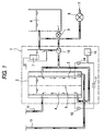
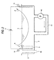


Classifications
-
- G—PHYSICS
- G03—PHOTOGRAPHY; CINEMATOGRAPHY; ANALOGOUS TECHNIQUES USING WAVES OTHER THAN OPTICAL WAVES; ELECTROGRAPHY; HOLOGRAPHY
- G03F—PHOTOMECHANICAL PRODUCTION OF TEXTURED OR PATTERNED SURFACES, e.g. FOR PRINTING, FOR PROCESSING OF SEMICONDUCTOR DEVICES; MATERIALS THEREFOR; ORIGINALS THEREFOR; APPARATUS SPECIALLY ADAPTED THEREFOR
- G03F7/00—Photomechanical, e.g. photolithographic, production of textured or patterned surfaces, e.g. printing surfaces; Materials therefor, e.g. comprising photoresists; Apparatus specially adapted therefor
- G03F7/26—Processing photosensitive materials; Apparatus therefor
- G03F7/30—Imagewise removal using liquid means
- G03F7/3042—Imagewise removal using liquid means from printing plates transported horizontally through the processing stations
- G03F7/3071—Process control means, e.g. for replenishing
Definitions
- the present invention relates to a method and an apparatus for developing a photosensitive resin composition supported on a substrate used in the production of a lithographic printing plate, a printed wiring substrate or an integrated circuit.
- the present invention relates to a developing method and a development processing apparatus, where a material having a plurality of photosensitive resin composition sheets can be stably processed using an automatic developing machine.
- the present invention relates to a developing method and a development processing apparatus, where a lithographic printing plate precursor such as PS plate can be stably developed in the plate-making process.
- the present invention relates to a plate-making method of a heat mode-type photosensitive image recording material which can be used as an offset printing master.
- the present invention relates to a plate-making method of a lithographic printing plate having a photosensitive layer comprising an infrared laser use positive photosensitive composition, which can be used in the so-called direct plate-making process of directly producing a printing plate based on digital signals of a computer or the like.
- a printed wiring substrate or an integrated circuit such as photosensitive lithographic printing plate (hereinafter sometimes simply referred to as "PS plate")
- the step of developing a layer of a material having a photosensitive resin composition provided on a substrate generally proceeds in such a manner that a part of the photosensitive resin composition of a printing plate precursor including a photosensitive lithographic printing plate precursor dissolves out into an alkali developer and thereby the development is performed. Therefore, the alkaline developer in the development tank diminishes in the activity due to the consumption of the alkali agent component.
- a method of supplying a replenisher containing an alkali agent or a buffer in a higher concentration than the developer in the development tank and thereby compensating the alkali consumption is usually used.
- This replenishing method is necessary for stably developing a large amount of a light-sensitive resin composition using a development processing apparatus but this method has the following problems.
- U.S. Patent 2,541,488 discloses a diazo image formation method of forming a dye by the diazo coupling reaction using hydroxy ion generated on the electrolysis. Differently from the developer, this method is realized in a newly prepared reaction system not having organic and inorganic resin components and free of a fear for poisoning. This system is different from the photosensitive resin composition as an object of the present invention.
- the development of a material having a photosensitive resin composition accompanied with replenishment has another problem that when the replenishment is controlled using the pH as usual, high precision of replenishment cannot be satisfactorily maintained.
- the developer for materials having a photosensitive resin composition is designed to maintain a low salt concentration and a high pH in practice so as to accelerate the dissolving out of unnecessary composition components. Accordingly, generation of even a slight amount of hydroxy ion or hydrogen ion in the developer affects the performance of the developer. Nevertheless, due to the high pH of developer, the pH insensibly responds to the fluctuation in the alkali component concentration.
- the pH value used for the control must be strictly set with respect to the tolerance width and a technique of replenishing a large amount of developer to inhibit the fluctuation of pH and thereby maintain stable development performance has been heretofore employed.
- This high replenishing ratio also contributes to the prevention of precipitation of the photosensitive resin composition components dissolved out.
- the prevention of exhaustion of the developer or the prevention of production of precipitates runs counter to the reduction in the amount of development replenisher or waste solution.
- the demand for a technique capable of realizing these two items at the same time is strong but not yet satisfied.
- JP-A-7-285275 proposes a positive image recording material containing a binder such as cresol resin, a substance capable of absorbing light and thereby generating heat, and a substance which is thermally decomposable and in the non-decomposed state, substantially reduces the solubility of the binder, such as quinonediazide.
- the substance capable of absorbing light and thereby generating heat causes heat generation in the exposed area upon exposure by an infrared ray laser, so that solubility of the exposed area can be obtained.
- the problems in the environmental issue, profitability, maintenance of quality or working operation come out as a large detect at the time of performing the development processing.
- the heat-mode printing plate is small in the discrimination by the exposure, therefore, readily affected even by a fluctuation factor on a level of causing no problem in conventional techniques.
- One example is the deterioration in the developability during the storage aging.
- the developingability of the photosensitive layer is gradually deteriorated and a serious difference is caused in the developability between the time immediately after the coating and the time after the storage aging. This difference brings about fluctuation in the finished quality of development, namely, fluctuation in the quality of printing plate.
- One object of the present invention is to provide a development processing method comprising continuously or intermittently developing a material having a photo-sensitive resin composition while maintaining the performance of the developer in the developing tank by the replenishment using a development processing solution, in which the problems described above can be overcome, the amount of the development replenisher, the replenishing agent or development waste solution can be reduced, and stable development quality can be constantly obtained. More specifically, the object is to provide a method for developing a material having a photosensitive resin composition using a development processing apparatus, in which the dissolved components are not precipitated even with a small replenishing amount, the amount of waste solution discharged can be reduced, and the development quality can be stably maintained without causing any impairment.
- Another object of the present invention is to provide a development processing method capable of performing the plate-making in a heat mode directly from the digital information of a computer or the like, which is free of any effect by the change in aging during the storage of the lithographic printing plate precursor (hereinafter, sometimes, called "lithographic printing original plate”) and mostly free of the effect by the fluctuation in the development conditions within a day or over days and can stably manufacture a printing plate.
- lithographic printing original plate lithographic printing plate precursor
- Still another object of the present invention is to provide a development processing apparatus suitable for the above-described lithographic printing plate precursor, in which the developability can be maintained for a long period of time.
- the present inventors have made investigations for satisfying both of the requirement for a small amount of waste solution discharged with a small replenishing amount and the requirement for high development quality with stable operation, by studying whether any effect is provided on the activation of exhausted developer when a current is passed through the developer, then, a fundamental prospect is gained.
- a problem remains in practice, that is, stable control and maintenance of the pH value. Therefore, extensive investigations have made to find out proper control means, as a result, it is unexpectedly found that the objects can be obtained by selecting an appropriate index for the degree of exhaustion of the developer and controlling the replenishing rate in correspondence with the fluctuation in the index, without controlling the replenishment by monitoring the pH value.
- the present invention has been accomplished based on this finding.
- the present inventors have made extensive investigations on the means for reducing the fluctuation in the development performance due to aging of the original plate (i.e., the printing plate precursor) or working conditions and stably maintaining the performance of developer, which can be used in the development processing of a photosensitive lithographic printing original plate capable of direct print-making in a heat-mode.
- the activity of the developer can be stably maintained in high precision, the deterioration in the developability during the storage aging of the printing original plate (i.e., the printing plate precursor) does not come out in any form, and the storage stability of the developability can be improved.
- the present invention has been accomplished also based on this finding.
- the present invention is characterized by the use of detection means in place of the pH value for detecting the exhaustion of developer occurring with the development, differently from the developing method (e.g., in an activator processing) using means for generating electrolysis of alkali components known in the field of silver halide photographic light-sensitive materials.
- the developer of silver salt light-sensitive materials is sufficient in the buffering ability and scarcely undergoes irregular changes of pH not participating in the exhaustion of developer, therefore, it is sufficient to adjust the pH to the standard value.
- the pH readily undergoes changes having no correspondence to the photographic performance and the pH insensibly responds to the change in the amounts of alkali components ascribable to the development. Therefore, it is not suitable to control the amount of alkali supplied by the pH value, but another detection means capable of correctly reflecting the exhaustion and not relying on the pH is necessary.
- the present invention has been accomplished by finding out such detection means.
- the preferred detection means for detecting the exhaustion of developer which is a main feature of the present invention, includes the following three means.
- the o-quinonediazide as a photoreceptor is converted into a carboxylic acid upon sensitization and dissolves in the developer to consume the alkali.
- the relationship between the alkali consumption and the pH change is not simply fixed, whereas the amount of photosensitive material processed corresponds to the amount of alkali agent consumed and moreover, serves as an index capable of exact reading. Therefore, by using the amount of photosensitive material processed as an index, the degree of exhaustion of the developer can be exactly detected.
- the developer for materials having a photosensitive resin composition usually has high alkalinity such that the pH is 12 or more, mostly 12.5 or more, and at the same time, has low salts concentration, therefore, the developer absorbs carbon dioxide gas in air at a high rate. In acute correspondence to the amount of carbon dioxide gas absorbed, the development activity decreases. Accordingly, in proportion to the interval where the development is not performed in the development processing apparatus, the aging deterioration of developer due to the carbon dioxide gas proceeds.
- the pH value cannot serve as an index for the aging deterioration ascribable to the absorption of carbon dioxide gas but the integrated time of intervals where the development is not performed can serve as an index for controlling the amount of alkali supplied, namely, means for appropriately detecting the exhaustion.
- interval where the development is not performed means a sum of two cases; one is in the state where the power source of the development processing apparatus is turned on, the temperature and the replenishing system are ready and the development can start on feeding of a material having a photosensitive resin composition, namely, a so-called stand-by state, and another is in the dead state where the power source of the development processing apparatus is turned off.
- the carbon dioxide gas absorbing rate does not differ so largely between the stand-bay state and the dead state where neither the temperature control nor the stirring of developer is done, therefore, even when intervals of two cases are integrated while neglecting the slight difference therebetween, the precision in the control of developer is not greatly affected. If the difference between the stand-by state and the dead state can not be neglected, the correction may be carried out according to each the absorbing rate. The correction may be conducted by calculating the average value or by calculating a replenishing amount every the integrated times.
- the degree of exhaustion of the developer occurring with the development is detected by the method in (1) above and the degree of exhaustion of the developer occurring with development and aging (stand-by and dead of apparatus) is detected by the method (3) described below.
- the physical detection means physical property values other than pH value can be used.
- the alkali component is consumed by the development and this must appear as the decrease of hydroxy ion, namely, pH, the decrease of electric conductivity the increase of specific gravity and the increase of opacity.
- the pH value does not correctly reflect the exhaustion of developer due to various combined factors, whereas physical property values other than pH respond in correspondence to the exhaustion and can be used as the means for detecting the degree of exhaustion.
- the physical property values preferably used to this purpose are electric conductivity (hereinafter referred to as "electroconductivity"), specific gravity and opacity.
- the electroconductivity unexpectedly well reflects the exhaustion.
- the conditions of high alkali concentration and low salts concentration seem to be advantageous for the detection means because the hydroxy ion can greatly contributes to the electroconductivity and the concentration thereof nearly corresponds to the electroconductivity.
- the exhaustion of developer is brought about by both the processing exhaustion occurring with the processing of a material having a photosensitive composition and the aging exhaustion due to absorption of carbon dioxide gas in the environment in the state where the development is not performed. Therefore, by determining the degree of exhaustion using in combination the processed area of a material having a photosensitive resin composition and the integrated time of aging intervals in the state where the development is not performed, including the stand-by state, the precision in the feeding of alkali can be more improved.
- an aqueous solution of salts may be prepared separately from the developer.
- use of the developer actually used is particularly advantageous because the preparation of electrolytic solution is not necessary (or the amount of the electrolytic solution can be greatly reduced) and since the current-carrying tank can be directly connected to the developer bath, the solution may be used in circulation by introducing the exhausted developer into the current-carrying tank and activating the developer in the current-carrying tank.
- the amount of developer discharged as the waste solution after the use in the development can be greatly reduced within the range of not causing precipitation of organic materials (e.g., polymer compound) dissolved out in the developer.
- the hydrogen ion may be used for accelerating the water washing in the water washing step subsequent to the development of a material having a photosensitive resin composition or may be used for the neutralization operation as a preparatory treatment before the discharge of the developer waste solution.
- the method of the present invention can be free of any deterioration in the electrolytic efficiency due to poisoning. This unexpected effect is considered to result because the developer in the developing tank is stabilized in the method of the present invention where the feeding of alkali is controlled by a proper index.
- the development processing solution (hereinafter referred to as "developer") to which the developing method of the present invention can be applied includes commercially available general-purpose developers. That is, the developing method of the present invention can be used in the development of various materials having a photosensitive resin composition, namely, a photosensitive material for lithographic printing, a photosensitive material for printed wiring substrates or a photoresist for forming a high definition (i.e., high accurate) pattern of an integrated circuit or the like.
- the developing method of the present invention is preferably used in the development of a photosensitive material for lithographic printing, more preferably in the development of a PS plate, particularly, a positive photosensitive resin composition.
- the developer for use in the development of a material having a photosensitive resin composition is preferably a developer having a pH of from 9.0 to 14.0, more preferably from 12.0 to 13.5.
- the developer referred to in the present specification means both the development initiating solution (developer in a narrow meaning) and the development replenisher.
- a conventionally well-known alkali aqueous solution may be used.
- examples thereof include inorganic alkali agents such as sodium silicate, potassium silicate, sodium tertiary phosphate, potassium tertiary phosphate, ammonium tertiary phosphate, sodium secondary phosphate, potassium secondary phosphate, ammonium secondary phosphate, sodium carbonate, potassium carbonate, ammonium carbonate, sodium hydrogen-carbonate, potassium hydrogencarbonate, ammonium hydrogen-carbonate, sodium borate, potassium borate, ammonium borate, sodium hydroxide, ammonium hydroxide, potassium hydroxide and lithium hydroxide; and organic alkali agents such as monomethylamine, dimethylamine, trimethylamine, monoethylamine, diethylamine, triethylamine, monoisopropylamine, diisopropylamine, triisopropylamine, n-butylamine, monoethanolamine, diethanolamine, triethanolamine, monois
- alkali agents are used individually or in combination of two or more thereof.
- the developer capable of more successfully bringing out the effect of the present invention is an aqueous solution containing preferably an alkali metal silicate and having a pH of 12 or more.
- the aqueous solution of alkali metal silicate can be controlled in the developability by the ratio of silicone oxide SiO 2 as a component of the silicate to the alkali metal oxide M 2 O (the ratio is generally expressed by the molar ratio of [SiO 2 ]/[M 2 O]), and the concentrations thereof.
- an aqueous solution of sodium silicate having an SiO 2 /Na 2 O molar ratio of from 1.0 to 1.5 (namely, [SiO 2 ]/[Na 2 O] is from 1.0 to 1.5) and having an SiO 2 content of from 1 to 4 wt% disclosed in JP-A-54-62004
- an aqueous solution of alkali metal silicate having an SiO 2 /M molar ratio of from 0.5 to 0.75 namely, [SiO 2 ]/[M 2 O] is from 1.0 to 1.5
- having an SiO 2 concentration of from 1 to 4 wt% and containing at least 2% of potassium based on the gram atom of all alkali metals present in the developer described in JP-B-57-7427 (the term "JP-B" as used herein means an "examined Japanese patent publication”) may be suitably used.
- the developer may contain, if desired, various surface active agents and organic solvents for the purpose of enhancing the developability, dispersing the development residue or increasing the ink receptivity on the image area of a printing plate.
- various surface active agents and organic solvents for the purpose of enhancing the developability, dispersing the development residue or increasing the ink receptivity on the image area of a printing plate.
- Preferred examples of the surface active agent include anionic, cationic, nonionic and amphoteric surface active agents.
- surface active agents may be used individually or in combination of two or more thereof.
- the surface active agent is added to the developer in an amount of from 0.001 to 10 wt%, more preferably from 0.01 to 5 wt%.
- the developer may further contain an organic solvent.
- the solvent used here suitably has a solubility in water of about 10 wt% or less, preferably 5 wt% or less.
- Examples thereof include 1-phenylethanol, 2-phenylethanol, 3-phenyl-1-propanol, 4-phenyl-1-butanol, 4-phenyl-2-butanol, 2-phenyl-1-butanol, 2-phenoxyethanol, 2-benzyloxyethanol, o-methoxybenzyl alcohol, m-methoxybenzyl alcohol, p-methoxybenzyl alcohol, benzyl alcohol, cyclohexanol, 2-methylcyclohexanol, 3-methylcyclohexanol, 4-methylcyclohexanol, N-phenylethanolamine and N-phenyldiethanolamine.
- the organic solvent content is from 0.1 to 5 wt% based on the total weight of the solution used.
- the amount of the organic solvent used has a close relation to the amount of the surface active agent used. As the amount of organic solvent increases, the amount of the surface active gent is preferably increased. This is because if the amount of surface active agent is small and the organic solvent is used in a large amount, the organic solvent does not completely dissolve and good developability cannot be ensured.
- the developer may contain, if desired, an antiseptic, a coloring agent, a thickener, a defoaming agent and a hard water-softening agent.
- the hard water-softening agent include polyphosphoric acid, sodium, potassium and ammonium salts of polyphosphoric acid, ethylenediaminetetraacetic acid, diethylenetriaminepentaacetic acid, triethylenetetraminehexaacetic acid, hydroxyethylethylenediaminetriacetic acid, nitrilotriacetic acid, aminopolycarboxylic acid such as 1,2-diaminocyclohexanetetraacetic acid and 1,3-diamino-2-propanoltetraacetic acid, sodium, potassium and ammonium salts of the aminopolycarboxylic acid, aminotri(methylenephosphonic acid), ethylenediaminetetra(methylenephosphonic acid), diethylenetriaminepenta(methylenephosphonic acid), triethylenetetraminehex
- the proper amount of the hard water-softening agent added varies depending on the chelating ability thereof, the hardness of hard water and the amount of hard water, however, the amount used is generally from 0.01 to 5 wt%, preferably from 0.01 to 0.5 wt% based on the developer on use. If the amount added is less then this range, the intended object may not be satisfactorily attained, whereas if the amount added exceeds this range, there arise adverse effects on the image area, such as color stripping.
- the printing original plate (i.e., the printing plate precursor) after the development is subjected to an after-treatment with washing water, a rinse containing a surface active agent and the like, or a desensitizing solution containing gum arabi or a starch derivative as described in JP-A-54-8002, JP-A-55-115045 and JP-A-59-58431.
- these processing operations may be performed by variously combining them.
- the lithographic printing plate obtained through these processing operations is mounted on an offset printing press and used for printing a large number of sheets.
- a conventionally well-known plate cleaner for PS plates may be used and examples thereof include CL-1, CL-2, CP, CN-4, CN, CG-1, PC-1, SR and IC [all produced by Fuji Photo Film Co., Ltd.].
- any method such as (1) a method of introducing the developer underwent the current-carrying in the cathode chamber into the replenishing tank, (2) a method of replenishing the solution underwent the current-carrying in the cathode chamber to the developing tank and (3) a method of replenishing the solution underwent the current-carrying in the cathode chamber to the circulation route of the developing tank, may be used.
- the form of (3) is preferred.
- any development processing apparatus (sometimes called developing apparatus) used for general purpose on the market or publicly known may be used.
- a developing tank necessary for dissolving the imagewise alkali-soluble region of a material having a photosensitive resin composition in the developer is indispensable.
- the developing apparatus usually has a rinsing tank (washing tank) for use in the washing after the development, a desensitization processing tank and a drying part.
- an apparatus combined with the above-described after-treatment step may also be used.
- the present invention is characterized in that hydroxy ion produced by the current-carrying is used as an alkali agent for the replenishment and detection means not relying on the pH is used for determining the degree of exhaustion of the developer. Therefore, the developing apparatus is also described mainly concerning these characteristic features.
- Fig. 1 is a schematic view showing the structure of an electrolytic device for use in one embodiment of the present invention.
- the electrolytic device 1 is constituted by an electrolytic cell 2 and a pipeline 12 for transferring the cathode solution to the developing tank of a developing apparatus (not shown) and in this embodiment, further comprises a pipeline 13 for transferring the anode solution to the development stopping tank of a developing apparatus and a pipeline 10 for replenishing the electrolytic solution to the electrolytic device.
- the electrolytic cell 2 is divided into an anode chamber 3 and a cathode chamber 4 by the diaphragm 5. In respective electrolytic chambers, an anode 14 and a cathode 15 are provided.
- a dc current voltage is applied by voltage applying means 17 (a rectifier and an ac power source, or a battery, and control of applied voltage).
- the control part 16 controls the current-carrying.
- the diaphragm 5 may be sufficient if it has permeability to solutions to such an extent that the electroconductivity between the cathode chamber and the anode chamber is ensured, it can prevent the solutions in both tanks from excessively mixing, and it is free of attack by the developer or anode solution.
- Examples of the material which can be preferably used for the diaphragm include a neutral and porous membrane free of attack by the developer or anode solution (for example, biscuit porcelain plate), a polymer hydrophobic porous membrane [for example, commercially available Goatex Film (produced by Goatex)] and a polymer osmotic membrane [for example, commercially available MF (microfilter) film, UF (ultrafiltration) film, RO (reverse osmosis) film].
- a neutral and porous membrane free of attack by the developer or anode solution for example, biscuit porcelain plate
- a polymer hydrophobic porous membrane for example, commercially available Goatex Film (produced by Goatex)
- a polymer osmotic membrane for example, commercially available MF (microfilter) film, UF (ultrafiltration) film, RO (reverse osmosis) film.
- an ion exchange membrane may also be used and both an anion exchange membrane (for example, those under the product names Selemion AWV/AMR and Anion-Type Aciplex produced by Asahi Glass Company, Ltd.) and a cation exchange membrane (Nafion produced by Du Pont and Flemion and Cation-Type Aciplex produced by Asahi Glass Company, Ltd.) are suitable for the object of the present invention.
- an anion exchange membrane for example, those under the product names Selemion AWV/AMR and Anion-Type Aciplex produced by Asahi Glass Company, Ltd.
- a cation exchange membrane Nafion produced by Du Pont and Flemion and Cation-Type Aciplex produced by Asahi Glass Company, Ltd.
- a divalent selective anion exchange membrane is preferred because of less mixing of the anode solution and the cathode solution and small increase of the electric resistance.
- any material may be used as long as it is an electro-inactive material.
- Preferred examples of the anode material include lead dioxide, graphite, lead and platinum, such as commercially available carbon sheet (Kuresheet, produced by Kureha Chemical Industry Co., Ltd.).
- Examples of the cathode material which can be used include stainless steel (e.g., SUS303, SUS316), copper, silver, graphite, lead and platinum, such as commercially available SUS316 (NTK316, produced by Nippon Kinzoku Co., Ltd.). These electrode materials are available on the market.
- the developer is suitably used and for the purpose of compensating the evaporated content during the term of continuing the development, the developer may be used after diluting it with water to some extent.
- this electrolytic device The action in this electrolytic device is described below.
- a voltage is applied between the anode 14 and the cathode 15 to allow a current to pass, hydroxy ion and hydrogen ion are produced in the cathode chamber and the anode chamber to cause a change toward alkalinity and acidity, respectively.
- the cathode solution is fed to the developing tank as a replenisher through the pipeline 12, whereby the development activity in the developing tank is maintained and the development is stably performed.
- the anode chamber and the cathode chamber are partitioned by the diaphragm and prevented from directly mixing each other.
- the solution preparing tank 6 substantially serves both as a solution preparing tank for preparing a fresh developer and as a reservoir tank for reserving the used developer for the reuse. More specifically, fresh water 11 is fed through a valve 8 and a developing agent is charged thereinto to prepare a developer. Other than that, an overflow solution (not shown) returned from the developing tank may be reserved. In either case, the developer prepared or reserved in this tank is transferred to the cathode chamber through a valve 10, where a current is passed to supply an alkali component (hydroxy ion) and thereby the developer is put into the state of replenisher. The replenisher is transferred to the developing tank though the liquid transferring pipeline 12, thereby performing the replenishment.
- the anode solution may be prepared in the solution preparing tank 6 and fed to the anode chamber.
- the liquid level in each of the anode chamber and the cathode chamber is maintained constant by using a level sensor 7 and changing over a valve to allow fresh water 11 or the solution in the solution preparing tank 6 to flow into the chamber.
- the used developer is reserved in the solution preparing tank 6, activated into the composition of the replenisher in the electrolytic cell and then reused.
- the developer may be used but it may be a solution prepared by dissolving only the inorganic salt component of the developer composition in water.
- a used developer may also be used and in this case, the pH is already lowered at the disposal as a development waste solution and therefore, the disposal advantageously costs low in proportion with the reduction of pH.
- the current-carrying is suitably performed at a current density of from 0.1 to 10 A/dm 2 , preferably from 0.1 to 5 A/dm 2 , more preferably from 0.5 to 5 A/dm 2 .
- the applied voltage is controlled so that the current density can fall in this range.
- the applied voltage varies depending on the shape of the apparatus, particularly, the distance between electrodes and the concentration of electrolyte in the developer, and it is usually from 1 to 100 V, preferably from 2 to 10 V.
- the electrode area varies according to the substantial volume of the objective developing tank but an almost proper value can be obtained by a relative calculation while regarding the electrode area as 1 dm 2 when the volume of the developing tank is 1 liter.
- the current-carrying time is about 40 seconds per the amount necessary for developing 1 m 2 of a photosensitive resin composition.
- the detection means for reading the degree of exhaustion of the developer to practice the replenishment determines the exhaustion, as described above, using one of three means or a combination thereof, namely, the reading of the processed amount in the development, the integration of intervals where the developing apparatus is in the stand-by state and the dead state, and the reading of a physical property value of developer other than the pH, preferably one of the electroconductivity, the specific gravity and the opacity, more preferably the electroconductivity (i.e., electric conductivity).
- a device for integrating the amount of photosensitive resin composition processed which is measured by an infrared sensor or obtained by the contact measurement, is disposed in the development processing apparatus.
- the processed amount is obtained as an area from the time of the photosensitive resin composition being transported to the developing tank, and the width and transportation speed of the composition.
- the processed amounts obtained are integrated.
- the thus-obtained information on the processed amount in the development is sent to the control part 16 of the electrolytic device shown in Fig. 1.
- the above-described device for integrating the processed amounts is known and being used in practice.
- the power source of the developing apparatus is turned on by a timer capable of recording the operating condition of the developing machine and respective intervals in the stand-by state and in the dead state of the developing machine are integrated and recorded.
- the operation for compensating the effect of the carbon dioxide gas is performed by applying a voltage to the electrolytic cell every each time when the integrated value of the stand-by intervals exceeds 4 hours, and thereby passing (i.e., carrying) an electrolytic current. If the development processing apparatus is in the dead state, the dead intervals are integrated and when the power source of the development processing apparatus is turned on next time, a current is passed for a time period in correspondence to the intervals integrated until that time.
- an electroconductivity meter is disposed at an appropriate site in the circulating system of the developer, preferably in the developing tank or in the stirring and circulating part of the developing tank.
- the thus-obtained information relating to the exhaustion of developer is sent to the control part 16 of Fig. 1 and thereby the duration of applying a voltage to electrodes is controlled.
- the duration of applying a voltage is selected, as a standard, such that the quantity of current-carrying is 600 coulomb per 1 m 2 of the processed amount.
- the duration of applying a voltage varies depending on the thickness of the coated layer of photosensitive resin composition or the amount of components dissolved out (in turn, the exposure amount and the like) and must be controlled according to the actual working.
- the duration of applying a voltage is selected, as a standard, for the development processing apparatus on an average scale, such that the quantity of current-carrying is 600 coulomb when the integrated time of the stand-by intervals and the integrated time of the dead intervals each is 4 hours.
- the carbon dioxide gas concentration in an indoor environment varies depending on the seasonal change, the work concurrently proceeding or the ventilating condition, therefore, needless to say, the current-carrying time must be further controlled in practice.
- the electrolysis time is preferably controlled such that the change of electroconductivity falls within 5%, preferably 2%, more preferably 1% of the standard value.
- the electroconductivity is from 40,000 to 60,000 ⁇ s/cm.
- the change of 1% is 500 ⁇ s/cm and this value is a value which can be read by an electroconductivity meter in good precision.
- the electroconductivity of which change responds only to the change in the hydrogen ion concentration is advantageous as an index and this is more sensitive to the exhaustion of developer than the pH value which logarithmically responds.
- an electro-conductivity meter always monitors the electroconductivity of developer during the operation of the development processing apparatus and the information obtained is transmitted to the control unit in Fig. 1.
- the control unit in Fig. 1 applies a voltage between the electrodes 14 and 15 based on the information.
- the current-carrying time reaches 20 seconds, the quantity of current-carrying becomes 300 coulomb. If the electroconductivity is recovered to the range within 1% of the standard value at this time, the application of voltage is terminated, but if not recovered to the range within 1%, the current is continuously passed until the next control cycle. By this control sequence, the current-carrying and the replenishment are controlled.
- the above-described three methods for controlling the replenishment may be used either individually or in combination. In view of the stability in the development step, the combination use of those three methods for controlling the replenishment is most preferred. Next preferred is the control by the electroconductivity or the combination of the information on the processed amount in the development with the control based on the information on the integrated time of intervals in the operable state.
- the initial physical property value (initial value) is taken as a basis and by reading the change from the initial value, the current-carrying time is controlled according to the value read, because those physical property values each varies along with the development.
- hydroxy ion is generated in the cathode chamber and the developer is activated as described above.
- hydrogen ion is generated in the anode chamber and this hydrogen ion can also be used in the development processing. More specifically, when the anode solution containing hydrogen ion generated in the anode chamber side by the current-carrying is used to form a part or the whole of washing water (also serves as a stopping solution) in the water washing step subsequent to the development of a material having a photosensitive resin composition, the water washing can be effectively performed such that the non-dissolved area of the photosensitive resin composition is prevented from excessively swelling and also increased in the physical strength.
- the components dissolved out during the development may be insolubilized and precipitated in the washing water waste solution.
- the components are separated from the waste solution and the waste solution can be easily treated.
- the apparatus in this system where hydrogen ion generated by the current-carrying is also used is described in more detail in the Examples.
- the used developer may be used as the anode solution, so that the alkali component can be neutralized and the load on the treatment of waste solution can be reduced.
- a function sharing system using two units of electrolytic cells may be used, where two units of electrolytic cells are provided, one unit is always current-carried at a current quantity capable of attaining current-carrying large enough to compensate the aging deterioration due to the absorption of carbon dioxide gas in air at the time when the development is not performed, and another unit is current-carried only when the development is performed, so as to compensate the exhaustion due to the development processing.
- the electrolytic device for the compensation of the effect by the absorption of carbon dioxide gas is always current-carried irrespective of the development processing time or the dead time, therefore, the electrolytic device for the compensation of the exhaustion of developer occurring with the development processing does not of course compensate the exhaustion due to the absorption of carbon dioxide gas.
- the electrolytic device for the compensation of the exhaustion of developer occurring with the development processing may employ, as means for detecting the exhaustion of developer, the processed amount in the development or a physical property value such as electroconductivity, specific gravity and opacity.
- the material having a photosensitive resin composition to which the present invention can be applied may be any of a photosensitive material for lithographic printing, a photosensitive material for printed wiring substrate and a photoresist for forming a high definition pattern of an integrated circuit or the like.
- a photosensitive material for lithographic printing is preferred, a PS plate is more preferred, and a positive photosensitive resin composition is still more preferred.
- the positive photosensitive resin composition may be sufficient if it can vary in the solubility or swellability in the developer between before and after the exposure.
- the composition is also used as a PS plate in many cases.
- the photosensitive agent is preferably an o-quinonediazide compounds.
- the o-quinonediazide compound is preferably a compound having at least one o-quinonediazide group and capable of increasing in the solubility in an alkali aqueous solution by an active light.
- the positive photosensitive resin composition is suitably a sulfonic acid ester of a hydroxyl compound of various types with o-benzoquinonediazide or o-naphthoquinonediazide.
- the photosensitive resin composition which is a positive photosensitive resin composition but not o-quinonediazide
- a chemical amplification-type photo-sensitive resin composition obtained by combining a water-insoluble and alkali-soluble compound in which the alkali soluble group is protected by an acid decomposition group, with a photoacid generating agent may be used.
- the photosensitive resin composition adopting the chemical amplification system is used as a lithographic printing material or a photoresist for the high definition microfabrication of an integrated circuit or the like. The development of this composition is attained using the alkali solubilization of the exposed area.
- the photoacid generating agent for use in the chemical amplification system may be a known one.
- the photoacid generating agent may be appropriately selected from the compound group consisting of photoinitiators for photo-cationic polymerization, photoinitiators for photoradical polymerization, photodecolorizing agents for dyes, photodiscoloring agents, compounds capable of generating an acid by known light being used for microresist and the like, and mixtures thereof.
- the water-insoluble and alkali-soluble compound used in combination with the photoacid generating agent in the chemical amplification-type photosensitive resin composition, in which the alkali soluble group is protected by an acid decomposition group is a compound having a -C-O-C- or -C-O-Si- bond. Examples thereof include the following compounds:
- alkali-soluble resin examples include phenol ⁇ formaldehyde resin, cresol ⁇ formaldehyde resin, phenol ⁇ cresol ⁇ formaldehyde copolycondensed resin, phenol-modified xylene resin, polyhydroxystyrene, polyhalogenated- hydroxystyrene, copolymers of N-(4-hydroxyphenyl)methacrylamide and hydroquinone monomethacrylate copolymer, and additionally include sulfonylimide-based polymers described in JP-A-7-28244 and carboxyl group-containing polymers described in JP-A-7-36814.
- alkali-soluble polymer compounds such as acrylic resin containing a phenolic hydroxyl group disclosed in JP-A-51-34711, acrylic resin having a sulfonamide group described in JP-A-2-866 and urethane-based resin may also be used.
- the alkali-soluble polymer compound preferably has a weight average molecular weight of from 500 to 20,000 and a number average molecular weight of from 200 to 60,000.
- alkali-soluble polymer compounds may be used individually or in combination of two or more thereof.
- the alkali-soluble polymer compound is added in an amount of 80 wt% or less based on the entire composition.
- a material having a photopolymerizable photosensitive resin composition which is one of the materials having a photosensitive resin composition for use in the present invention, is described below.
- the main component of the photopolymerizable photosensitive resin composition for use in the present invention is a compound containing an addition-polymerizable ethylenical double bond, a photopolymerization initiator or the like. If desired, a compound such as thermal polymerization inhibitor is added thereto.
- the compound containing an addition-polymerizable double bond may be freely selected from the compounds having at least one, preferably two or more, terminal ethylenically unsaturated bond.
- the compound has a chemical form of, for example, a monomer, a prepolymer (e.g., dimer, trimer, oligomer), a mixture thereof or a copolymer thereof.
- Examples of the monomer and the copolymer thereof include esters of unsaturated carboxylic acid (e.g., acrylic acid, methacrylic acid, itaconic acid, crotonic acid, isocrotonic acid, maleic acid) with an aliphatic polyhydric alcohol compound, and amides of unsaturated carboxylic acid with an aliphatic polyhydric amine compound.
- esters of unsaturated carboxylic acid e.g., acrylic acid, methacrylic acid, itaconic acid, crotonic acid, isocrotonic acid, maleic acid
- amides of unsaturated carboxylic acid with an aliphatic polyhydric amine compound.
- the photopolymerization initiator contained in the photopolymerizable photosensitive resin composition for use in the present invention may be appropriately selected from various photopolymerizable initiators known in the patents and publications (e.g., literature), and combination systems (photopolymerization initiating systems) using two or more photopolymerization initiators, according to the wavelength of the light source used.
- benzyl, benzoin ether, Michler's ketone, anthraquinone, thioxanthone, acridine, phenazine and benzophenone are widely used.
- the present invention can be applied not only to the above-described positive PS plate using a compound having quinonediazide or an alkali-soluble group protected by an acid decomposable group or negative PS plate using a photopolymerization system but also to lithographic printing plate materials described below and resists for forming a printed wiring or an integrated circuit:
- the coated amount (solid content) of the image-forming layer obtained after the coating and drying varies depending on the use end, however, in the case of a general lithographic printing original plate, it is preferably from 0.5 to 5.0 g/m 2 , more preferably from 0.5 to 1.5 g/m 2 .
- the thickness of the layer is from 0.01 to 100 ⁇ m, preferably from 0.1 to 10 ⁇ m, more preferably from 0.3 to 1 ⁇ m.
- the photosensitive resin composition is coated on a support selected according to the use end.
- a dimensionally stable plate-like material is used.
- the support which can be used in the present invention include paper, paper laminated with plastic (e.g., polyethylene, polypropylene, polystyrene), a metal plate (e.g., aluminum, zinc, copper, nickel, stainless steel), plastic film (e.g., cellulose diacetate, cellulose triacetate, cellulose propionate, cellulose butyrate, cellulose acetate butyrate, cellulose nitrate, polyethylene terephthalate, polyethylene, polystyrene, polypropylene, polycarbonate, polyvinyl acetal), and paper or plastic film laminated or deposited with a metal described above.
- plastic e.g., polyethylene, polypropylene, polystyrene
- a metal plate e.g., aluminum, zinc, copper, nickel, stainless steel
- plastic film e.g., cellulose dia
- the substrate for use in the present invention has a thickness of approximately from 0.05 to 0.6 mm, preferably from 0.1 to 0.4 mm, more preferably from 0.15 to 0.3 mm.
- the aluminum sheet is, if desired, subjected to a degreasing treatment with, for example, a surface active agent, an organic solvent or an alkaline aqueous solution so as to remove the rolling oil on the surface.
- a degreasing treatment with, for example, a surface active agent, an organic solvent or an alkaline aqueous solution so as to remove the rolling oil on the surface.
- the thus-prepared lithographic printing plate is usually subjected to imagewise exposure and development.
- Examples of the light source emitting an active (light) ray for use in the imagewise exposure include mercury lamp, metal halide lamp, xenon lamp, chemical lamp and carbon arc lamp.
- Examples of the radio active ray include electron beam, X ray, ion beam and far infrared ray.
- g ray, i ray, Deep-UV light or high-density energy beam (laser beam) may be used.
- Examples of the laser beam include helium ⁇ neon laser, argon laser, krypton laser, helium ⁇ cadmium laser and KrF eximer laser.
- a light source having a light emission wavelength in the region of from near infrared to far infrared is preferred, and a solid laser and a semiconductor laser are more preferred.
- the printing original plate comprising the materials described above is transported to the development part through the heating part of the processing apparatus, where the plate is dipped in a developer reserved, for example, in a developing tank and thereby developed.
- the present invention also provides a method for developing a photosensitive lithographic printing plate precursor described in claim 10. That is, the photosensitive lithographic printing plate precursor used is a lithographic printing original plate having a photosensitive layer formed by coating an infrared laser use positive photosensitive composition containing at least (A) an alkali-soluble polymer compound, (B) a compound which compatibilizes with the alkali-soluble polymer compound to reduce the solubility of the polymer compound in an alkali aqueous solution and is diminished in the action of reducing the solubility on heating and (C) a compound which absorbs light and thereby generates heat, wherein the activity of the developer is maintained by passing a current between electrodes of current-carrying means appending to development means and having a cathode chamber, an anode chamber and electrodes, through the developer in the cathode chamber.
- A an alkali-soluble polymer compound
- B a compound which compatibilizes with the alkali-soluble polymer compound to reduce the solubility
- the development processing method of the present invention is characterized in that the activity is imparted by electrolysis and the hydroxy ion generated by the current-carrying prevents the reduction in the activity of developer, so that the stable development quality can be maintained.
- the above-described photosensitive printing original plate has a property such that the developability deteriorates in aging. The degree of deterioration varies depending on the time period of storing the original plate (i.e., the printing plate precursor) used.
- the above-described defect does not come out into a serious problem.
- the fluctuation in the development conditions within a day or over days scarcely causes any effect, so that the developability can be stably maintained.
- the photosensitive lithographic printing original plate to which the development processing method of the present invention is applied is preferably a lithographic printing original plate having a photosensitive layer containing, in addition to the constituent components (A), (B) and (C) described above, (D) a cyclic acid anhydride represented by the following formula (I): wherein R 1 and R 2 each independently represents hydrogen atom or an alkyl, alkenyl, alkoxy, cycloalkyl, aryl, carbonyl, carboxy or carboxylic acid ester group having from 1 to 12 carbon atoms, which may have a substituent, and R 1 and R 2 may be combined with each other to form a ring structure.
- R 1 and R 2 each independently represents hydrogen atom or an alkyl, alkenyl, alkoxy, cycloalkyl, aryl, carbonyl, carboxy or carboxylic acid ester group having from 1 to 12 carbon atoms, which may have a substituent, and R 1 and R 2 may be combined with each
- the activity of developer is maintained by controlling the quantity of current passed between electrodes through the developer according to the degree of exhaustion of the developer occurring with the development and thereby controlling the production of hydroxy ion supplied to the developer.
- the means for detecting the exhaustion of developer occurring with the development is selected from the following three means:
- the hydroxy ion is generated in the cathode chamber and this is used for maintaining the activity of developer.
- hydrogen ion is also generated in the anode chamber and as described in claim 14, this hydrogen ion is introduced into a processing bath of the washing or stopping step subsequent to the development step, and reduces the pH, so that the water washing or stopping can be accelerated and also the load on the treatment of development waste solution discharged can be reduced.
- the developing apparatus of claim 15 is a developing apparatus for use in the development processing of photosensitive lithographic printing original plates, comprising development means for sequentially processing photosensitive lithographic printing original plates with a developer, detection means for detecting the exhaustion of developer occurring with the development or with the aging of developer, current-carrying means for passing a current between electrodes through the developer to generate hydroxy ion, and circulation means (i.e., liquid transfer means) for connecting the development means and the current-carrying means.
- development means for sequentially processing photosensitive lithographic printing original plates with a developer
- detection means for detecting the exhaustion of developer occurring with the development or with the aging of developer
- current-carrying means for passing a current between electrodes through the developer to generate hydroxy ion
- circulation means i.e., liquid transfer means
- the current-carrying means is an electrolytic device comprising a cathode chamber, an anode chamber, a porous membrane or a liquid junction for enabling current-carrying between the cathode chamber and the anode chamber, and electrodes provided in respective chambers, where hydroxy ion and hydrogen ion are generated in the cathode chamber and the anode chamber, respectively, by the electrolysis of water.
- the developing apparatus described in claim 16 is an apparatus for use in the embodiment of using the hydrogen ion generated in the anode chamber in the washing or stopping step, where in addition to the above-described means, washing or stopping means and liquid transfer means for connecting the current-carrying means and the anode chamber are provided.
- the image formation mechanism is considered to proceed as follows: (A) an alkali-soluble polymer compound (hereinafter sometimes called "Component (A)”) is combined with (B) a compound which has a group capable of interacting with the alkali-soluble polymer compound within the molecule and compatibilizes with the polymer compound to reduce the solubility of the polymer compound in an alkali aqueous solution and also which is diminished in the action of reducing the solubility by the heating (hereinafter sometimes called “Component (B)”) and (C) a compound which absorbs light and thereby generates heat, so that Component (B) can uniformly compatibilizes with Component (A) at the film formation to reduce the solubility of Component (A) in an alkali aqueous solution.
- Component (B) a compound which has a group capable of interacting with the alkali-soluble polymer compound within the molecule and compatibilizes with the polymer compound to reduce the solubility of the polymer compound in an alkali aque
- this photosensitive original plate has a property such that Component (B) changes in aging of the original plate to cause a change in the pH of the photosensitive composition of the original plate and since the photosensitization process is a thermal reaction, the discriminating property is inferior to that of the conventional light-mode photosensitive original plate and even a slight change in the activity of the developer gives a large effect.
- the electrolytic activation-type developing method of the present invention the supply of hydroxy ion generated on electrolysis seems to prevent occurring of this change.
- the electrolytic activation-type developing method is known in the field of development of silver halide light-sensitive materials, however, there is no effect on the developer for printing original plates such as PS plate, having an extremely high pH and poor buffering property, therefore, this method has been not put into practical use.
- the photosensitive lithographic printing original plate, the exposing and developing method for recording an image, the development processing apparatus, and the plate-making method for use in the present invention are described in sequence below.
- This printing original plate for use in the present invention is described below.
- This printing original plate comprises a support having thereon a photosensitive layer formed by coating an infrared laser use positive photosensitive composition (hereinafter sometimes simply referred to as a "photosensitive composition") and if desired, further comprises other layers.
- an infrared laser use positive photosensitive composition hereinafter sometimes simply referred to as a "photosensitive composition”
- the infrared laser use positive photosensitive composition contained in the photosensitive layer comprises (A) an alkali-soluble polymer compound, (B) a compound which compatibilizes with the alkali-soluble polymer compound to reduce the solubility of said polymer compound in an alkali aqueous solution and is diminished in the action of reducing said solubility on heating, (C) a compound which absorbs light and thereby generates heat and (D) a cyclic acid anhydride represented by formula (I) and further contains, if desired, other components.
- the alkali-soluble polymer compound for use in the present invention is not particularly limited as long as it is conventionally known, however, the compound is preferably a polymer compound having any one functional group of (A-1) a phenolic hydroxyl group, (A-2) a sulfonamide group and (A-3) an active imide group within the molecule.
- Examples of the polymer compound having (A-1) a phenolic hydroxyl group include novolak resins such as phenol formaldehyde resin, m-cresol formaldehyde resin, p-cresol formaldehyde resin, m-/p-cresol mixture formaldehyde resin, phenol/cresol (any of m-cresol, p-cresol and a mixture of m-cresol and p-cresol) and mixed formaldehyde resin, and pyrogallol acetone resin.
- novolak resins such as phenol formaldehyde resin, m-cresol formaldehyde resin, p-cresol formaldehyde resin, m-/p-cresol mixture formaldehyde resin, phenol/cresol (any of m-cresol, p-cresol and a mixture of m-cresol and p-cresol) and mixed formaldehyde resin, and pyrogallol acetone resin.
- polymer compounds having a phenolic hydroxyl group on the side chain are preferably used as the polymer compound having a phenolic hydroxyl group.
- examples of the polymer compound having a phenolic hydroxyl group on the side chain include polymer compounds obtained by homopolymerizing a polymerizable monomer comprising a low molecular compound having one or more unsaturated bond polymerizable with a phenolic hydroxyl group, or copolymerizing this monomer with another polymerizable monomer.
- Examples of the polymerizable monomer having a phenolic hydroxyl group include acrylamide, methacrylamide, acrylic acid ester, methacrylic acid ester and hydroxystyrene each having a phenolic hydroxy group.
- polymerizable monomer examples include N-(2-hydroxyphenyl)acrylamide, N-(3-hydroxyphenyl)acrylamide, N-(4-hydroxyphenyl)acrylamide, N-(2-hydroxyphenyl)methacrylamide, N-(3-hydroxyphenyl)methacrylamide, N-(4-hydroxyphenyl)methacrylamide, o-hydroxyphenyl acrylate, m-hydroxyphenyl acrylate, p-hydroxyphenyl acrylate, o-hydroxyphenyl methacrylate, m-hydroxyphenyl methacrylate, p-hydroxyphenyl methacrylate, o-hydroxystyrene, m-hydroxystyrene, p-hydroxystyrene, 2-(2-hydroxyphenyl)ethyl acrylate, 2-(3-hydroxyphenyl)ethyl acrylate, 2-(4-hydroxyphenyl)ethyl acrylate, 2-(2-hydroxyphenyl)ethyl acrylate
- These resins having a phenolic hydroxy group may be used in combination of two or more thereof.
- alkali-soluble polymer compound having (A-2) a sulfonamide group examples include polymer compounds obtained by homopolymerizing a polymerizable monomer having a sulfonamide group or copolymerizing this monomer with another polymerizable monomer.
- polymerizable monomer having a sulfonamide group examples include polymerizable monomers comprising a low molecular compound having at least one sulfonamide group -NH-SO 2 - bonded to at least one hydrogen atom on the nitrogen atom and at least one polymerizable unsaturated bond within one molecule.
- low molecular compounds having an acryloyl group, an allyl group or a vinyloxy group, and a substituted or monosubstituted aminosulfonyl group or a substituted sulfonylimino group are preferred.
- Examples of this compound include the compounds represented by the following formulae (II) to (VI): wherein X 1 and X 2 each represents -O- or -NR 7 -, R 1 and R 4 each represents hydrogen atom or -CH 3 , R 2 , R 5 , R 9 , R 12 and R 16 each represents an alkylene, cycloalkylene, arylene or aralkylene group having from 1 to 12 carbon atoms which may have a substituent, R 3 , R 7 and R 13 each represents hydrogen atom or an alkyl, cycloalkyl, aryl or aralkyl group having from 1 to 12 carbon atoms which may have a substituent, R 6 and R 17 each represents an alkyl, cycloalkyl, aryl or aralkyl group having from 1 to 12 carbon atoms which may have a substituent, R 8 , R 10 and R 14 each represents hydrogen atom or -CH 3 , R 11 and R 15 each represents a single bond or an
- the compound which can be suitably used, include m-aminosulfonylphenyl methacrylate, N-(p-aminosulfonylphenyl)methacrylamide and N-(p-aminosulfonylphenyl)acrylamide.
- the alkali-soluble polymer compound having (A-3) an active imide group preferably has an active imide group represented by the formula shown below within the molecule and examples of this polymer compound include polymer compounds obtained by homopolymerizing a polymerizable monomer comprising a low molecular compound having at least one active imide group represented by the formula shown below and at least one polymerizable unsaturated bond within one molecule, or copolymerizing this monomer with another polymerizable monomer.
- this compound which can be suitably used, include N-(p-toluenesulfonyl)methacrylamide and N-(p-toluenesulfonyl)acrylamide.
- alkali-soluble polymer compound for use in the present invention a polymer compound obtained by polymerizing two or more of a polymerizable monomer having a phenolic hydroxyl group, a polymerizable monomer having a sulfonamide group and a polymerizable monomer having an active imide group, which are described above, or a polymer compound obtained by copolymerizing two or more of these polymerizable monomers with another polymerizable monomer is preferably used.
- the weight ratio of these components blended is preferably from 50:50 to 5:95, more preferably from 40:60 to 10:90.
- the alkali-soluble polymer compound is a copolymer of the above-described polymerizable monomer having a phenolic hydroxyl group, polymerizable monomer having a sulfonamide group or polymerizable monomer having an active imide group with another polymerizable monomer
- the monomer capable of imparting alkali solubility is preferably contained in an amount of 10 mol% or more, more preferably 20 mol% or more. If the amount of the component copolymerized is less than 10 mol%, the alkali solubility is liable to be insufficient and the effect of improving the development latitude may not be sufficiently achieved.
- Examples of the monomer component copolymerized with the above-described polymerizable monomer having a phenolic hydroxyl group, polymerizable monomer having a sulfonamide group or polymerizable monomer having an active imide group include the following monomers (1) to (12), however, the present invention is by no means limited thereto:
- the alkali-soluble polymer compound when the alkali-soluble polymer compound is a homopolymer or a copolymer of a polymerizable monomer having a phenolic hydroxyl group, a polymerizable monomer having a sulfonamide group or a polymerizable monomer having an active imide group, a polymer compound having a weight average molecular weight of 2,000 or more and a number average molecular weight of 500 or more is preferred, and a polymer compound having a weight average molecular weight of from 5,000 to 300,000, a number average molecular weight of from 800 to 250,000 and a dispersion degree (weight average molecular weight/number average molecular weight) of from 1.1 to 10 is more preferred.
- the alkali-soluble polymer compound is a resin such as phenol formaldehyde resin or cresol aldehyde resin
- those having a weight average molecular weight of from 500 to 20,000 and a number average molecular weight of from 200 to 10,000 are preferred.
- alkali-soluble polymer compounds may be used either individually or in combination of two or more thereof.
- the alkali-soluble polymer compound is used in an amount of from 30 to 99 wt%, preferably from 40 to 95 wt%, more preferably from 50 to 90 wt%, based on all solid contents of the photosensitive composition. If the amount of the alkali-soluble polymer compound added is less than 30 wt%, the photosensitive layer is deteriorated in the durability, whereas if it exceeds 99 wt%, disadvantageous effects may result in both the sensitivity and the durability.
- Component (B) indicates a compound having good compatibility with (A) an alkali-soluble polymer compound to form a uniform coating solution owing to the action of the hydrogen-bonding functional group present in the molecule and at the same time having a function of inhibiting the alkali solubility of Component (A) by the interaction with Compound (A).
- the thermal decomposition temperature of Component (B) is preferably 150°C or more.
- Component (B) for use in the present invention include compounds capable of interacting with Component (A), such as sulfone compound, ammonium salt, phosphonium salt and amide compound.
- Component (B) must be appropriately selected by taking account of the interaction with Component (A) and to speak specifically, for example, when a novolak resin is solely used as Component (A), Cyanine Dye A and the like described later are suitably used.
- the blended ratio of Component (A) to Component (B) is usually preferably from 99/1 to 75/25. If Component (B) is less than 99/1, the interaction with Component (A) insufficiently proceeds, then the alkali solubility cannot be inhibited and the image formation may not be successfully performed, whereas if Component (B) exceeds 75/25, the interaction excessively proceeds to extremely decrease the sensitivity. Thus, the blended ratio outside the above-described range is not preferred.
- the compound which absorbs light and generates heat means a compound having light absorption in the infrared region at 700 nm or more, preferably from 750 to 1,200 nm, and exhibiting a light/heat converting function with light having a wavelength in this range.
- various pigments and dyes which absorb light in this wavelength region to generate heat may be used.
- pigments examples include commercially available pigments and pigments described in Color Index (C.I.) Binran (C.I. Handbook) , Saishin Ganryo Binran (Handbook of Latest Pigments) , compiled by Nippon Ganryo Gijutsu Kyokai (1977), Saishin Ganryo Oyo Gijutsu (Up-To-Date Pigment Application Technology) , CMC (1986), and Insatsu Ink Gijutsu (Printing Ink Technology) , CMC (1984).
- the kind of pigment includes black pigment, yellow pigment, orange pigment, brown pigment, red pigment, ultraviolet pigment, blue pigment, green pigment, fluorescent pigment, metal powder pigment and polymer bond pigment.
- Specific examples of the pigment which can be used include insoluble azo pigments, azo lake pigments, condensed azo pigments, chelate azo pigments, phthalocyanine-based pigments, anthraquinone-based pigments, perylene- and perynone-based pigments, thioindigo-based pigments, quinacridone-based pigments, dioxazine-based pigments, isoindolinone-based pigments, quinophthalone-based pigments, dyed lake pigments, azine pigments, nitroso pigments, nitro pigments, natural pigments, fluorescent pigments, inorganic pigments and carbon black.
- These pigments may not be surface treated or may be surface treated before use.
- a method of coating resin or wax on the surface a method of attaching a surface active agent and a method of bonding a reactive substance (for example, silane coupling agent, an epoxy compound and polyisocyanate) to the pigment surface may be used.
- a reactive substance for example, silane coupling agent, an epoxy compound and polyisocyanate
- the pigment preferably has a particle size of from 0.01 to 10 ⁇ m, more preferably from 0.05 to 1 ⁇ m, still more preferably from 0.1 to 1 ⁇ m. If the particle size of pigment is less than 0.01 ⁇ m, the dispersion is not stable in view of the stability in the coating solution for the photosensitive layer, whereas if it exceeds 10 ⁇ m, the photosensitive layer disadvantageously cannot be homogeneous.
- dispersing the pigment For dispersing the pigment, a known dispersion technique for use in the production of ink or toner may be used.
- the disperser include ultrasonic disperser, sand mill, attritor, pearl mill, super-mill, ball mill, impeller, disperser, KD mill, colloid mill, dynatron, three roll mill and pressure kneader. These are described in detail in Saishin Ganryo Oyo Gijutsu (Up-To-Date Pigment Application Technology) , CMC (1986).
- dyes commercially available dyes and known dyes described in publications (for example, Senryo Binran (Handbook of Dyes) , compiled by Yuki Gosei Kagaku Kyokai (1970)) may be used. Specific examples thereof include dyes such as azo dye, metal complex salt azo-dye, pyrazolone azo dye, anthraquinone dye, phthalocyanine dye, carbonium dye, quinoneimine dye, methine dye and cyanine dye.
- azo dye such as azo dye, metal complex salt azo-dye, pyrazolone azo dye, anthraquinone dye, phthalocyanine dye, carbonium dye, quinoneimine dye, methine dye and cyanine dye.
- pigments and dyes those which absorb infrared light or near infrared light are preferred in the present invention because they are suitable for the use with a laser emitting infrared or near infrared light.
- the pigment which absorbs infrared or near infrared light carbon black is suitably used.
- the dye which absorbs infrared or near infrared light include cyanine dyes described in JP-A-59-202829 and JP-A-60-78787, methine dyes described in JP-A-58-194595, naphthoquinone dyes described in JP-A-59-48187, JP-A-59-73996 and JP-A-60-52940, squarylium dyes described in JP-A-58-112792, cyanine dyes described in British Patent 434,875, and dihydropyrimidinesquarylium dyes described in U.S. Patent 5,380,635.
- the near infrared absorbing sensitizers described in U.S. Patent 5,156,938 are suitably used.
- substituted arylbenzo(thio)pyrylium salts described in U.S. Patent 3,881,924, trimethinethiapyrylium salts described in JP-A-57-142645 (corresponding to U.S. Patent 4,327,169) pyrylium-based compounds described in JP-A-58-220143, JP-A-59-146063 and JP-A-59-146061
- cyanine dyes described in JP-A-59-216146 pentamethinethiapyrylium salts described in U.S.
- Patent 4,283,475 pyrylium compounds described in JP-B-5-13514 and JP-B-5-19702, Epolight III-178, Epolight III-130, Epolight III-125 and Epolight IV-62A are preferably used.
- the dye or pigment may be added to the photosensitive composition in an amount of from 0.01 to 50 wt%, preferably from 0.1 to 10 wt%, in the case of a dye, more preferably from 0.5 to 10 wt% and in the case of a pigment, more preferably from 3.1 to 10 wt%, based on all solids content of the photosensitive layer. If the amount of pigment or dye added is less than 0.01 wt%, the sensitivity decreases, whereas if it exceeds 50 wt%, the homogeneity of the photosensitive layer is lost and the durability of the photosensitive layer deteriorates.
- the dye or pigment may be added to the same layer as the layer to which other components are added or may be added to a layer provided separately. In the case of adding to a separate layer, it is preferred to add to a layer adjacent to the layer containing a substance which is thermally decomposable and in the non-decomposed state, substantially reduces the solubility of the alkali-soluble polymer compound for use in the present invention.
- the dye or pigment and the alkali-soluble polymer compound are preferably added to the same layer but may be added to separate layers.
- one compound having the properties of both of (B) the compound which compatibilizes with said alkali-soluble polymer compound to reduce the solubility of said polymer compound in an alkali aqueous solution and is diminished in the action of reducing said solubility on heating and (C) the compound which absorbs light and thereby generates heat (hereinafter, the compound is referred to as "Component (B+C)") may be used in place of Components (B) and (C).
- Examples of the compound include those represented by the following formula (VII):
- R 1 to R 4 each independently represents hydrogen atom or an alkyl, alkenyl, alkoxy, cycloalkyl or aryl group having from 1 to 12 carbon atoms which may have a substituent, and R 1 and R 2 or R 3 and R 4 may be combined to form a ring structure.
- R 1 to R 4 each specifically represents hydrogen atom, a methyl group, an ethyl group, a phenyl group, a dodecyl group, a naphthyl group, a vinyl group, an aryl group and a cyclohexyl group.
- substituents include a halogen atom, a carbonyl group, a nitro group, a nitrile group, a sulfonyl group, a carboxyl group, a carboxylic acid ester and a sulfonic acid ester.
- R 5 to R 10 each independently represents an alkyl group having from 1 to 12 carbon atoms which may have a substituent.
- R 5 to R 10 each specifically represents a methyl group, an ethyl group, a phenyl group, a dodecyl group, a naphthyl group, a vinyl group, an allyl group or a cyclohexyl group.
- substituents include a halogen atom, a carbonyl group, a nitro group, a nitrile group, a sulfonyl group, a carboxyl group, a carboxylic acid ester and a sulfonic acid ester.
- R 11 to R 13 each independently represents hydrogen atom, a halogen atom or an alkyl group having from 1 to 8 carbon atoms which may have a substituent.
- R 12 may be combined with R 11 or R 13 to form a ring structure.
- a plurality of substituents R 12 may be combined with each other to form a ring structure.
- R 11 to R 13 each specifically represents chlorine atom, a cyclohexyl group or a cyclopentyl or cyclohexyl ring resulting from the combining of substituents R 12 .
- substituents include a halogen atom, a carbonyl group, a nitro group, a nitrile group, a sulfonyl group, a carboxyl group, a carboxylic acid ester and a sulfonic acid ester.
- m represents an integer of from 1 to 8, preferably from 1 to 3.
- R 14 and R 15 each independently represents hydrogen atom, a halogen atom or an alkyl group having from 1 to 8 carbon atoms which may have a substituent.
- R 14 and R 15 may be combined to form a ring structure.
- a plurality of substituents R 14 may be combined with each other to form a ring structure.
- R 14 and R 15 each specifically represents chlorine atom, a cyclohexyl group or a cyclopentyl or cyclohexyl ring resulting from the combining of substituents R 14 .
- substituents include a halogen atom, a carbonyl group, a nitro group, a nitrile group, a sulfonyl group, a carboxyl group, a carboxylic acid ester and a sulfonic acid ester.
- m represents an integer of from 1 to 8, preferably from 1 to 3.
- X - represents an anion.
- the anion include perchloric acid, tetrafluoroboric acid, hexafluorophosphoric acid, triisopropylnaphthalenesulfonic acid, 5-nitro-o-toluenesulfonic acid, 5-sulfosalicylic acid, 2,5-dimethylbenzenesulfonic acid, 2,4,6-trimethylbenzenesulfonic acid, 2-nitrobenzenesulfonic acid, 3-chlorobenzenesulfonic acid, 3-bromobenzenesulfonic acid, 2-fluorocaprylnaphthalenesulfonic acid, dodecyl-benzenesulfonic acid, 1-naphthol-5-sulfonic acid, 2-methoxy-4-hydroxy-5-benzoyl-benzenesulfonic acid and p-toluenesulfonic acid.
- the compound represented by formula (VII) is a compound commonly called a cyanine dye.
- Specific examples of the compound, which can be suitably used, include the following compounds, however, the present invention is by no means limited to these specific examples.
- Component (B+C) can be suitably used in the present invention because it has a property of absorbing light and generating heat, has an absorption in the infrared region of from 700 to 1,200 nm, exhibits good compatibility with the alkali-soluble polymer compound, is a basic dye, contains a group capable of interacting with the alkali-soluble polymer compound, such as ammonium group or iminium group, within the molecule (namely, having the property of Component (B)), and by virtue of this group, can interact with the polymer compound and thereby control the alkali solubility of the polymer compound.
- a group capable of interacting with the alkali-soluble polymer compound such as ammonium group or iminium group
- Component (B+C) compound having the properties of both Component (B) and Component (C), such as a cyanine dye is used in place of Components (B) and (C)
- the amount of the compound added is preferably in view of the sensitivity from 99/1 to 70/30, more preferably from 99/1 to 75/25, to Component (A).
- a cyclic acid anhydride is preferably used as an additional component.
- the cyclic acid anhydride is preferably a compound represented by formula (I) shown below, in which a bond conjugating with the carbonyl group of a carboxylic acid anhydride is present in the structure, therefore, the stability of the carbonyl group increases and the decomposition rate is controlled, as a result, decomposition proceeds at a proper rate during the storage aging to gradually generate an acid, so that the deterioration in the developability during the storage aging can be prevented. Accordingly, in maintaining the developer used in the developing method of the present invention for a long period of time, the object of the present invention can be more effectively attained.
- R 1 and R 2 each independently represents hydrogen atom or an alkyl, alkenyl, alkoxy, cycloalkyl, aryl, carbonyl, carboxy or carboxylic acid ester group having from 1 to 12 carbon atoms, which may have a substituent, and R 1 and R 2 may be combined with each other to form a ring structure.
- R 1 and R 2 each is preferably hydrogen atom or an unsubstituted alkyl, aryl, alkenyl or cycloalkyl group having from 1 to 12 carbon atoms. Specific examples thereof include hydrogen atom, a methyl group, an ethyl group, a phenyl group, a dodecyl group, a naphthyl group, a vinyl group, an aryl group and a cyclohexyl group.
- examples of the group formed include a phenylene group, a naphthylene group, a cyclohexene group and a cyclopentene group.
- examples of the substituent include a halogen atom, a hydroxy group, a carbonyl group, a sulfonic acid ester, a nitro group and a nitrile group.
- R 3 , R 4 , R 5 and R 6 each independently represents hydrogen atom, a hydroxy group, a halogen atom such as chlorine, a nitro group, a nitrile group or an alkyl, alkenyl, alkoxy, cycloalkyl, aryl, carbonyl, carboxy or carboxylic acid ester group having from 1 to 12 carbon atoms which may have a substituent.
- R 3 , R 4 , R 5 and R 6 each is preferably hydrogen atom, a halogen atom, an unsubstituted alkyl or alkenyl group having from 1 to 12 carbon atoms or an aryl group having from 6 to 12 carbon atoms. Specific examples thereof include a methyl group, a vinyl group, a phenyl group and an allyl group.
- examples of the substituent include a halogen atom, a hydroxy group, a carbonyl group, a sulfonic acid ester, a nitro group, a nitrile group and a carboxy group.
- cyclic acid anhydride which can be suitably used in the present invention, include phthalic acid anhydride, 3,4,5,6-tetrahydrophthalic acid anhydride, tetrachlorophthalic anhydride, 3-hydroxyphthalic acid anhydride, 3-phenylphthalic acid anhydride, trimellitic acid anhydride, pyromellitic acid anhydride, maleic acid anhydride, phenylmaleic acid anhydride, dimethylmaleic acid anhydride, dichloromaleic acid anhydride and chloromaleic acid anhydride.
- the ratio of the cyclic acid anhydride occupying in the photosensitive composition solid contents is preferably from 0.5 to 20 wt%, more preferably from 1 to 15 wt%, still more preferably from 1 to 10 wt%. If the content is less than 0.5 wt%, the effect of maintaining the developability is insufficient, whereas if it exceeds 20 wt%, an image is not formed. Thus, the content out of the above-described range is not preferred.
- the photosensitive composition of the lithographic printing original plate of the present invention may contain, if desired, various additives.
- a substance which is thermally decomposable and in the non-decomposed state substantially decreases the solubility of the alkali-soluble polymer compound, such as onium salt, o-quinonediazide compound, aromatic sulfone compound or aromatic sulfonic acid ester compound, is preferably used in combination from the standpoint of increasing the effect of inhibiting the dissolution of an image area in the developer.
- the alkali-soluble polymer compound such as onium salt, o-quinonediazide compound, aromatic sulfone compound or aromatic sulfonic acid ester compound
- onium salt examples include diazonium salts, ammonium salts, phosphonium salts, iodonium salts, sulfonium salts, selenonium salts and arsonium salts.
- onium salt used in the present invention known compounds over a wide range can be used. Although other known compounds may also be used for the printing original plate of the present invention, representative examples of respective known compound groups include diazonium salts described in S.I. Schlesinger, Photogr. Sci. Eng. , 18, 387 (1974), and T.S. Bal et al., Polymer , 21, 423 (1980), ammonium salts described in JP-A-3-140140, phosphonium salts described in D.C. Necker et al., Macromolecules , 17, 2468 (1984), and U.S. Patent 4,069,055, iodonium salts described in J.V.
- diazonium salts are preferred.
- preferred diazonium salts include those described in JP-A-5-158230.
- quinonediazides include o-quinonediazide compounds.
- the o-quinonediazide compound for use in the present invention is a compound having at least one o-quinonediazide group, which increases in the alkali solubility by the thermal decomposition, and compounds having various structures may be used. More specifically, the o-quinonediazide has properties such that the capability of inhibiting the dissolution or the binder is lost by the thermal decomposition and the o-quinonediazide itself is changed into an alkali-soluble substance and these two effects favor the solubility of the photosensitive material system. Examples of the o-quinonediazide compound, which can be used in the present invention, include the compounds described in J. Kosar, Light-Sensitive Systems , pp. 339-352, John Wiley & Sons.
- esters or sulfonic acid amides of o-quinonediazide obtained by reacting with an aromatic polyhydroxy or aromatic amino compound of various types are preferred.
- esters of benzoquinone(1,2)-diazidesulfonic acid chloride or naphthoquinone-(1,2)-diazide-5-sulfonic acid chloride with pyrogallol-acetone resin described in JP-B-43-28403 and esters of benzoquinone-(1,2)-diazidesulfonic acid chloride or naphthoquinone-(1,2)-diazide-5-sulfonic acid chloride with phenol-formaldehyde resin may be suitably used.
- esters of naphthoquinone-(1,2)-diazide-4-sulfonic acid chloride with phenolformaldehyde resin or cresol-formaldehyde resin may also be suitably used.
- the amount of onium salt, o-quinonediazide compound, aromatic sulfonic acid ester or the like added is preferably from 0.1 to 50 wt%, more preferably from 0.5 to 30 wt%, still more preferably from 0.5 to 20 wt%, based on all solid contents of the photosensitive composition.
- These compounds may be used individually or may be used as a mixture of several compounds.
- a general-purpose cyclic acid anhydride other than that represented by formula (I), a phenol, an organic acid or a sulfonyl compound may be used in combination.
- cyclic acid anhydride examples include tetrahydrophthalic acid anhydride, hexahydrophthalic anhydride and succinic acid anhydride described in U.S. Patent 4,115,128.
- phenols examples include bisphenol A, p-nitrophenol, p-ethoxyphenol, 2,4',4'-trihydroxybenzophenone, 2,3,4-trihydroxybenzophenone, 4-hydroxybenzophenone, 4,4',4''-trihydroxytriphenylmethane and 4,4',3'',4''-tetrahydroxy-3,5,3',5'-tetramethyltriphenylmethane.
- organic acids examples include sulfonic acids, sulfinic acids, alkylsulfuric acids, phosphonic acids, phosphoric acid esters and carboxylic acids, described in JP-A-60-88942 and JP-A-2-96755.
- Specific examples thereof include p-toluenesulfonic acid, dodecylbenzenesulfonic acid, p-toluenesulfinic acid, ethylsulfuric acid, phenylphosphonic acid, phenylphosphinic acid, phenyl phosphate, diphenyl phosphate, benzoic-acid, adipic acid, p-toluylic acid, 3,4-dimethoxybenzoic acid, phthalic acid, erucic acid, lauric acid, n-undecanoic acid, ascorbic acid, methylphenylsulfone and diphenyldisulfone.
- the ratio of the cyclic acid anhydride, phenol or organic acid occupying in the solid content of photosensitive composition is preferably from 0.05 to 20 wt%, more preferably from 0.1 to 15 wt%, still more preferably from 0.1 to 10 wt%.
- the photosensitive composition for use in the present invention may contain a nonionic surface active agent described in JP-A-62-251740 and JP-A-3-208514 or an amphoteric surface active agent described in JP-A-59-121044 and JP-A-4-13149 so as to broaden the processing stability against development conditions.
- nonionic surface active agent examples include sorbitan tristearate, sorbitan monopalmitate, sorbitan trioleate, stearic acid monoglyceride and polyoxyethylenenonylphenyl ether.
- amphoteric surface active agent examples include alkyldi(aminoethyl)glycine, alkylpolyaminoethyl glycine hydrochloride, 2-alkyl-N-carboxyethyl-N-hydroxyethylimidazolinium betaine and N-tetradecyl-N,N-betaine type (for example, AMORGEN K, trade name, produced by Daiichi Kogyo K.K.).
- the ratio of nonionic surface active agent or amphoteric surface active agent occupying in the solid content of photosensitive composition is preferably from 0.05 to 15 wt%, more preferably from 0.1 to 5 wt%.
- the photosensitive composition for use in the present invention may contain a printing out agent for obtaining a visible image immediately after the heating by exposure or a dye or pigment as an image coloring agent.
- a representative example of the printing out agent is a combination of a compound capable of releasing an acid on heating by exposure (photoacid releasing agent) and an organic dye capable of forming a salt.
- Specific examples thereof include a combination of o-naphthoquinonediazide-4-sulfonic acid halogenide and a salt-forming organic dye described in JP-A-50-36209 and JP-A-53-8128, and a combination of a trihalomethyl compound and a salt-forming organic dye described in JP-A-53-36223, JP-A-54-74728, JP-A-60-3626, JP-A-61-143748, JP-A-61-151644 and JP-A-63-58440.
- the trihalomethyl compound includes an oxazole-based compound and a triazine-based compound. Both compounds have excellent aging stability and gives a sharp printed image.
- dyes other than the above-described salt-forming organic dyes may also be used.
- Suitable dyes including the salt-forming organic dye are an oil-soluble dye and a basic dye.
- Oil Yellow #101, Oil Yellow #103, Oil Pink #312, Oil Green BG, Oil Blue BOS, Oil Blue #603, Oil Black BY, Oil Black BS, Oil Black T-505 (all produced by Orient Kagaku Kogyo K.K.), Victoria Pure Blue, Crystal Violet (C.I. 42555), Methyl Violet (C.I. 42535), Ethyl Violet, Rhodamine B (C.I. 45170B), Malachite Green (C.I. 42000) and Methylene Blue (C.I. 52015).
- Dyes described in JP-A-62-293247 and JP-A-5-313359 are particularly preferred.
- the dye may be added to the photosensitive composition in a ratio of from 0.01 to 10 wt%, preferably from 0.1 to 3 wt%, based on the solid content of photosensitive composition.
- the photosensitive composition for use in the present invention may further contain, if desired, a plasticizer for imparting flexibility to the coated film.
- a plasticizer for imparting flexibility to the coated film.
- examples thereof include butylphthalyl, polyethylene glycol, tributyl citrate, diethyl phthalate, dibutyl phthalate, dihexyl phthalate, dioctyl phthalate, tricresyl phosphate, tributyl phosphate, trioctyl phosphate, tetrahydrofurfuryl oleate, and oligomers and polymers of an acrylic acid or methacrylic acid.
- the photosensitive composition for use in the present invention may further contain, if desired, a photodecomposable compound such as quinonediazides and diazo compounds.
- a photodecomposable compound such as quinonediazides and diazo compounds.
- the amount of this compound added is preferably from 1 to 5 wt% based on the solid content of photosensitive composition.
- the photosensitive layer of the lithographic printing original plate of the present invention may be usually produced by dissolving the above-described components in a solvent and coating the resulting solution on an appropriate support.
- solvent used here examples include ethylene dichloride, cyclohexanone, methyl ethyl ketone, methanol, propanol, ethylene glycol monomethyl ether, 2-methoxyethyl acetate, 1-methoxy-2-propyl acetate, dimethoxyethane, ethyl lactate, N,N-dimethylacetamide, N,N-dimethylformamide, tetramethylurea, N-methylpyrrolidone, dimethylsulfoxide ⁇ -butyrolactone and toluene, however, the present invention is by no means limited thereto. These solvents are used individually or in combination.
- the concentration of the above-described components (all solids content containing additives) in the solvent is preferably from 1 to 50 wt%.
- the coated amount (solid content) on the support after the coating and drying varies depending on the use end, however, in the case of a photosensitive printing plate in general, it is preferably from 0.5 to 5.0 g/m 2 .
- various methods may be used and examples thereof include bar coater coating, rotation coating, spray coating, curtain coating, dip coating, air knife coating, blade coating and roll coating.
- the coated amount is smaller, the apparent sensitivity becomes higher but the film forming property of the photosensitive layer becomes poorer.
- the photosensitive layer may contain a surface active agent so as to improve the coatability, such as a fluorine-based surface active agent described, for example, in JP-A-62-170950.
- a surface active agent so as to improve the coatability, such as a fluorine-based surface active agent described, for example, in JP-A-62-170950.
- the amount of the surface active agent added is preferably from 0.01 to 1 wt%, more preferably from 0.05 to 0.5 wt%, based on all solids content of the photosensitive layer.
- a dimensionally stable, plate-like material may be used. Examples thereof include those described above
- polyester film and aluminum sheet are preferred, and aluminum sheet is more preferred because it is dimensionally stable and relatively inexpensive.
- the aluminum sheet is suitably a pure aluminum sheet or an alloy sheet mainly comprising aluminum and containing a trace amount of foreign elements.
- a plastic film laminated with or having deposited thereon aluminum may be used.
- the foreign element contained in the aluminum alloy include silicon, iron, manganese, copper, magnesium, chromium, zinc, bismuth, nickel and titanium.
- the foreign element content in the alloy is at most 10 wt% or less.
- pure aluminum is preferred, however, it is difficult to produce a completely pure aluminum in view of the smelting technology and therefore, an aluminum containing a trace amount of foreign elements may be used.
- the composition of the aluminum sheet for use in the present invention is not specified and an aluminum sheet comprising conventionally known materials may be appropriately used.
- the aluminum sheet as a substrate for use in the present invention preferably has a thickness of approximately from 0.1 to 0.6 mm, more preferably from 0.15 to 0.4 mm, still more preferably from 0.2 to 0.3 mm.
- the aluminum sheet is, if desired, subjected to a degreasing treatment with, for example, a surface active agent, an organic solvent or an alkaline aqueous solution so as to remove the rolling oil on the surface.
- a degreasing treatment with, for example, a surface active agent, an organic solvent or an alkaline aqueous solution so as to remove the rolling oil on the surface.
- the surface roughening (e.g., graining) of the aluminum sheet is performed by various methods, for example, by a method of mechanically roughening the surface, a method of electrochemically dissolving and roughening the surface or a method of chemically dissolving the selected surface.
- a known method such as ball polishing, brush polishing, blast polishing or buff polishing may be used.
- the electrochemical surface roughening may be performed by passing an alternating current or direct current through the electrolytic solution such as hydrochloric acid or nitric acid. These two surface roughening treatments may be used in combination as disclosed in JP-A-54-63902.
- the thus surface roughened aluminum sheet is, if desired, subjected to alkali etching and neutralization and further, if desired, to anodic oxidation so as to increase the water receptivity or abrasion resistance on the surface.
- the electrolyte for use in the anodic oxidation of aluminum sheet various electrolyte capable of forming a porous oxidation film may be used and in general, phosphoric acid, oxalic acid, chromic acid or a mixed acid thereof is used.
- the concentration of the electrolyte is appropriately selected according to the king of the electrolyte.
- the treating conditions in the anodic oxidation vary depending on the electrolyte used and cannot be indiscriminately specified, however, the conditions in general are properly such that the concentration of the electrolyte (solution) is from 1 to 80 wt%, the liquid temperature is from 5 to 70°C, the current density is from 5 to 60 A/dm 2 , the voltage is from 1 to 100 V, and the electrolysis time is from 10 seconds to 5 minutes.
- the amount of anodic oxidation film is less than 1.0 g/m 2 , a sufficiently long press life may not be obtained or the non-image area of the lithographic printing plate is readily scratched and so-called "scratch scumming" of allowing ink to adhere to the scratch part is liable to occur at the time of printing.
- the aluminum surface is, if desired, subjected to hydrophilization.
- an alkali metal silicate for example, an aqueous sodium silicate solution
- U.S. Patents 2,714,066, 3,181,461, 3,280,734 and 3,902,734 is known.
- the support is dipped or electrolyzed in an aqueous sodium silicate solution.
- a method of treating the support with potassium fluorozirconate disclosed in JP-B-36-22063 or with polyvinylphosphonic acid disclosed in U.S. Patents 3,276,868, 4,153,461 and 4,689,272 may be used.
- the lithographic printing original plate of the present invention comprises a support having provided thereon a photosensitive layer formed by coating an infrared laser-use positive photosensitive composition. If desired, an undercoat layer may be provided between the support and the photosensitive layer.
- organic compounds may be used. Examples thereof include carboxymethyl cellulose, dextrin, gum arabi, phosphonic acids having an amino group, such as 2-aminoethylphosphonic acid, organic phosphonic acids such as phenylphosphonic acid which may have a substituent, naphthylphosphonic acid, alkylphosphonic acid, glycerophosphonic acid, methylenediphosphonic acid and ethylenediphosphonic acid, organic phosphoric acids such as phenylphosphoric acid which may have a substituent, naphthylphosphoric acid, alkylphosphoric acid and glycerophosphoric acid, organic phosphinic acids such as phenylphosphinic acid which may have a substituent, naphthylphosphinic acid, alkylphosphinic acid and glycerophosphinic acid, amino acids such as glycine and ⁇ -alanine, and hydrochlorides of amine having a hydroxy group,
- the coverage of the organic undercoat layer is suitably from 2 to 200 mg/m 2 , preferably from 5 to 100 mg/m 2 . If this coverage is less than 2 mg/m 2 , a sufficiently long press life may not be obtained. The same goes for the case where the coverage exceeds 200 mg/m 2 .
- an overcoat layer may be provided on the photosensitive layer, if desired.
- the component for the overcoat layer include polyvinyl alcohol, methacrylate, acrylate and matting materials used in the ordinary photosensitive lithographic printing original plate.
- the thus-manufactured lithographic printing original plate is subjected to exposure in an appropriate heat mode, preferably exposure by an infrared laser, and development with an alkali development processing solution, thereby accomplishing the plate making.
- the photosensitive layer according to the present invention is advantageous in that a positive image can be formed using an infrared laser.
- the light source of emitting an active ray used for the imagewise exposure in the exposure step is preferably a light source having a light emitting wavelength of 700 nm or more in the region of from a far infrared to an infrared.
- the light source for use in the plate-making method of the present invention is preferably a solid laser capable of irradiating an infrared ray having a light emitting wavelength of from 700 to 1,200 nm, more preferably a semiconductor laser.
- the lithographic printing original plate may also be exposed using a heat mode-type light source other than the infrared laser.
- a heat mode-type light source other than the infrared laser.
- high-illuminance xenon flash light capable of acting as a heat ray, xenon arc light, light of tungsten halogen lamp or a laser light oscillating a wavelength in the visible region may be used.
- the development step of the photosensitive lithographic printing original plate of the present invention is described in detail below in the order of developer, replenishing method and developing apparatus.
- the development processing solution (called developer) to which the development processing method of the present invention can be applied is preferably a developer having a pH of from 9.0 to 14.0, more preferably from 12.0 to 13.5.
- the developer referred to in the present specification means both the developer in the state of a use solution filled in the developing tank and the development replenisher.
- the developers capable of more successfully bringing out the effect of the present invention are so-called “silicate developer” which is an aqueous solution having a pH of 12 or more and containing alkali silicate as a base or alkali silicate obtained by mixing a silicon compound with a base, and so-called “non-silicate developer” not containing alkali silicate and containing a non-reducing sugar and a base.
- the aqueous solution of alkali metal silicate can be controlled in the developability by the ratio of silicone oxide SiO 2 as a component of the silicate to the alkali metal oxide M 2 O (the ratio is generally expressed by the molar ratio of [SiO 2 ]/[M 2 O]), and the concentrations thereof.
- This aqueous solution may be used at a ratio and concentrations described above of respective components.
- non-silicate developer not containing alkali silicate and containing a non-reducing sugar and a base is also preferably used in the developing method of the present invention.
- the photosensitive lithographic printing original plate is developed using this developer, the surface of the photosensitive layer can be prevented from deteriorating and at the same time, the photosensitive layer can maintain its good inking state.
- the photosensitive lithographic printing original plate has a narrow development latitude and the line image width or the like greatly varies depending on the pH of developer.
- the non-silicate developer contains a non-reducing sugar having a buffering property of suppressing the fluctuation of pH, therefore, this developer is advantageous as compared with the developer containing silicate.
- the non-silicate developer is advantageous also in the point that the non-reducing sugar hardly contaminates the electro-conductivity sensor or pH sensor for controlling the degree of liquid activity as compared with silicate.
- the silicate developer and the non-silicate developer respectively have advantageous points and can be preferably used in the present invention.
- the non-reducing sugar is a sugar not containing a free aldehyde or ketone group and not exhibiting reducing property.
- the non-reducing sugar is classified into trehalose-type oligosaccharide where reducing groups are bonded to each other, glycoside where a reducing group of the sugar and a non-sugar are bonded, and sugar-alcohol obtained by hydrogenating and thereby reducing a sugar. These all are suitably used in the present invention.
- the non-reducing sugars described in JP-A-8-305039 are preferred.
- trehalose-type oligosaccharide examples include saccharose and trehalose.
- glycoside examples include alkyl glycoside, phenol glycoside and mustard oil glycoside.
- sugar-alcohol examples include D,L-arabitol, ribitol, xylitol, D,L-sorbitol, D,L-mannitol, D,L-iditol, D,L-talitol, dulcitol and allodulcitol.
- maltitol resulting from the hydrogenation of maltose as a disaccharide and a reduction product (reduced starch syrup) obtained by the hydrogenation of olicosaccharide may be suitably used.
- trehalose-type oligosaccharide and sugar-alcohol are preferred, and D-sorbitol, saccharose, reduced starch syrup are more preferred because these have a buffering action in a proper pH region and cost low.
- non-reducing sugars may be used either individually or in combination of two or more thereof.
- the content of the non-reducing sugar in the non-silicate developer is preferably from 0.1 to 30 wt%, more preferably from 1 to 20 wt%. If this content is less than 0.1 wt%, a sufficiently high buffering action may not be obtained, whereas if it exceeds 30 wt%, a high concentration may not be obtained and there arises a problem of increase in the cost.
- Examples of the base used in combination with the non-reducing sugar include conventionally known alkali agents such as inorganic alkali agents and organic alkali agents.
- Examples of the inorganic alkali agent include sodium hydroxide, potassium hydroxide, lithium hydroxide, trisodium phosphate, tripotassium phosphate, triammonium phosphate, disodium phosphate, dipotassium phosphate, diammonium phosphate, sodium carbonate, potassium carbonate, ammonium carbonate, sodium hydrogencarbonate, potassium hydrogencarbonate, ammonium hydrogencarbonate, sodium borate, potassium borate and ammonium borate.
- organic alkali agent examples include monomethylamine, dimethylamine, trimethylamine, monoethylamine, diethylamine, triethylamine, monoisopropylamine, diisopropylamine, triisopropylamine, n-butylamine, monoethanolamine, diethanolamine, triethanolamine, monoisopropanolamine, diisopropanolamine, ethyleneimine, ethylenediamine and pyridine.
- bases may be used either individually or in combination of two or more thereof.
- sodium hydroxide and potassium hydroxide are preferred because the pH can be adjusted in a wide pH region by controlling the amount thereof.
- trisodium phosphate, tripotassium phosphate, sodium carbonate and potassium carbonate are also preferred because these have a buffering action by themselves.
- the content of the base used here in the non-silicate developer is appropriately selected by taking account of the desired pH and the kind and added amount of the non-reducing sugar.
- the use of a reducing sugar in combination with the base is disadvantageous in the present invention because the reducing sugar is browned, the pH gradually lowers and the developability decreases.
- a non-silicate developer mainly comprising an alkali metal salt of the non-reducing sugar in place of the combination of a non-reducing sugar and a base, may be used.
- the alkali metal salt of the non-reducing sugar may be obtained by mixing the non-reducing sugar with an alkali metal hydroxide, heating and thereby dehydrating the mixture at a melting point or more of the non-reducing sugar or by drying an aqueous solution of a mixture of the non-reducing sugar and an alkali metal hydroxide.
- an alkaline buffer solution comprising a weak acid other than the above-described non-reducing sugar and a strong base may be used in combination.
- the weak acid preferably has a dissociation constant (pKa) of from 10.0 to 13.2 and may be selected from those described, for example, in Ionization Constants of Organic Acids in Aqueous Solution , Pergmon Press.
- pKa dissociation constant
- the weak acid which can be suitably used, include alcohols such as 2,2,3,3-tetrafluoropropanol-1 (pKa: 12.74), trifluoroethanol (pKa: 12.37) and trichloroethanol (pKa: 12.24); aldehydes such as pyridine-2-aldehyde (pKa: 12.68) and pyridine-4-aldehyde (pKa: 12.05); compounds having a phenolic hydroxide, such as salicylic acid (pKa: 13.0), 3-hydroxy-2-naphthoic acid (pKa: 12.84), catechol (pKa: 12.6), gallic acid (pKa: 12.4), sulfosalicylic acid (pKa: 11.7), 3,4-dihydroxysulfonic acid (pKa: 12.2), 3,4-dihydroxybenzoic acid (pKa: 11.94), 1,2,4-trihydroxybenzene (pKa: 11.82), hydroquino
- Examples of the strong base used in combination with this weak acid include sodium hydroxide, ammonium hydroxide, potassium hydroxide and lithium hydroxide.
- strong bases may be used either individually or in combination of two or more thereof.
- the strong base is used after adjusting the pH to fall within a preferred range by appropriately selecting the concentration and the combination.
- the processing is preferably performed under a so-called over-condition where the alkali concentration of the alkali development processing solution is increased so as to improve the developability, and this over-condition can be attained by controlling the amount of the base added. More specifically, the over-condition may be attained by adding the base to the alkali development processing solution so that the alkali development processing can have strong alkalinity, for example, the pH can fall within the range of from 12.5 to 13.5, preferably from 12.8 to 13.3.
- the developer may contain a surface active agent or organic solvent of various types, if desired, for the purpose of accelerating the developability, dispersing the development residue and increasing the ??ink receptivity in the image area of printing plate.
- a surface active agent or organic solvent of various types, if desired, for the purpose of accelerating the developability, dispersing the development residue and increasing the ??ink receptivity in the image area of printing plate.
- Preferred examples of the surface active agent include anionic, cationic, nonionic and amphoteric surface active agents.
- the surface active agents may be used either individually or in combination of two or more thereof and the surface active agent is added to the developer in an amount of from 0.001 to 10 wt%, preferably from 0.01 to 5 wt%.
- an organic solvent described above is added to the developer in an amount also-described above.
- the developer may further contain, if desired, an antiseptic, a coloring agent, a thickener, a defoaming agent and a hard water-softening agent, as described above.
- the proper amount of the hard water softening agent added varies depending on the chelating ability thereof, the hardness of hard water used, and the amount of the hard water, however, the hard water softening agent is preferably used in an amount described above.
- a replenishment is performed for compensating the consumption of developer components or dissolution of the original plate composition occurring with the development reaction, or the change in the developer composition due to contact with air during the storage aging before the use in the development of the original plate.
- the pH of developer is a representative property commonly used as an index in the implementation of replenishment.
- the replenishment is performed to keep the pH value constant or performed to increase the replenishing amount to a level where the control of replenishment using the representative property as an index is not necessary.
- the amount of the development waste solution discharged increases.
- the former method is disadvantageous for the heat-mode type photosensitive lithographic printing original plate of the present invention, because the pH greatly changes not in correspondence with the photographic performance as described above.
- the developer is activated by the replenishment such that a current is passed between electrodes through the developer and thereby hydroxy ion is supplied.
- the supply of hydroxy ion by the current-carrying is preferably performed according to the exhaustion of developer. Accordingly, detection means capable of correctly reflecting the degree of exhaustion and not relying on the pH is necessary. The present invention has been accomplished based on the finding of such detection means.
- the preferred detection means for detecting the exhaustion of developer which is a main feature of the present invention, include three means described below.
- the developer of the photosensitive lithographic printing original plate is usually highly alkaline with a pH of 12 or more, mostly 12.5 or more, and at the same time low in the concentration of salts, therefore, absorbs carbon dioxide gas in air at a high rate.
- the development activity acutely responds to the amount of carbon dioxide absorbed and decreases. Accordingly, in proportion with the interval where the development processing is not performed in the development processing solution, the deterioration in aging of the developer due to carbon dioxide gas proceeds.
- the pH value cannot serve as an index for the aging deterioration ascribable to the absorption of carbon dioxide gas but the integrated time of intervals where the development processing is not performed can serve as an index for use in the control of the amount of alkali supplied, namely, means for appropriately detecting the degree of exhaustion.
- interval where the development is not performed means a sum of two cases; one is in the state where the power source of the development processing apparatus is turned on, the temperature and the replenishing system are ready and the development can start on feeding of a photosensitive lithographic printing original plate material, namely, a so-called stand-by state, and another is in the dead state where the power source of the development processing apparatus is turned off.
- the carbon dioxide gas absorbing rate does not differ so largely between the stand-bay state and the dead state where neither the temperature control nor the stirring of developer is done, therefore, even when intervals of two cases are integrated while neglecting the slight difference therebetween, the precision in the control of developer is not greatly affected.
- the degree of exhaustion of the developer occurring with the development is detected by the method in (1) above and the degree of exhaustion of the developer occurring with the aging of the developer where the development processing is not performed is detected by the method in (2) above.
- the degree of exhaustion of the developer occurring with development and aging may also be detected by the method (3) described below.
- the physical detection means physical property values other than pH value can be used.
- the alkali component is consumed by the development and this must appear as the decrease of hydroxy ion, namely, pH, the decrease of electroconductivity, the increase of specific gravity and the increase of opacity.
- the pH value does not correctly reflect the exhaustion of developer due to various combined factors, whereas physical property values other than pH respond in correspondence to the exhaustion and can be used as the means for detecting the degree of exhaustion.
- the physical property values preferably used to this purpose are electric conductivity (hereinafter referred to as "electroconductivity"), specific gravity and opacity.
- the electroconductivity unexpectedly well reflects the exhaustion.
- the conditions of high alkali concentration and low salts concentration seem to be advantageous for the detection means because the hydroxy ion can greatly contributes to the electroconductivity and the concentration thereof nearly corresponds to the electro-conductivity.
- the method is superior to the methods (1) and (2) in that the degree of exhaustion of the developer can be directly read irrespective of the kind of the photosensitive lithographic printing original plate under the development processing or the difference at the storage aging after the production.
- the exhaustion of developer is brought about by both the processing exhaustion occurring with the processing of a photosensitive lithographic printing original plate and the aging exhaustion due to absorption of carbon dioxide gas in the environment in the state where the development is not performed. Therefore, by determining the degree of exhaustion using in combination the processed area of a photosensitive lithographic printing original plate and the integrated time of aging intervals in the state where the development is not performed, including the stand-by state, the precision in the feeding of alkali can be more improved.
- an aqueous solution of salts may be prepared separately from the developer.
- use of the developer actually used is particularly advantageous because the preparation of electrolytic solution is not necessary (or the amount of the electrolytic solution can be greatly reduced) and since the current-carrying tank can be directly connected to the developer bath, the solution may be used in circulation by introducing the exhausted developer into the current-carrying tank and activating the developer in the current-carrying tank.
- the amount of developer discharged as the waste solution after the use in the development can be greatly reduced within the range of not causing precipitation of organic materials (e.g., polymer compound) dissolved out in the developer.
- the hydrogen ion may be used for accelerating the water washing in the water washing step subsequent to the development of a photosensitive lithographic printing original plate or may be used for the neutralization operation as a preparatory treatment before the discharge of the developer waste solution.
- the method of the present invention can be free of any deterioration in the electrolytic efficiency due to poisoning. This unexpected effect is considered to result because the developer in the developing tank is stabilized in the method of the present invention where the feeding of alkali is controlled by a proper index.
- any method such as (1) a method of introducing the developer underwent the current-carrying in the cathode chamber into the replenishing tank, (2) a method of replenishing the solution underwent the current-carrying in the cathode chamber to the developing tank and (3) a method of replenishing the solution underwent the current-carrying in the cathode chamber to the circulation route of the developing tank, may be used.
- the form of (3) is preferred.
- the printing original plate after the development is subjected to an after-treatment with washing water, a rinse containing a surface active agent and the like, or a desensitizing solution containing gum arabi or a starch derivative, as described in JP-A-54-8002, JP-A-55-115045 and JP-A-59-58431.
- these processing operations may be performed by variously combining them.
- the lithographic printing plate obtained through these processing operations is mounted on an offset printer and used for printing a large number of sheets.
- a conventionally well-known plate cleaner for PS plates may be used and examples thereof include CL-1, CL-2, CP, CN-4, CN, CG-1, PC-1, SR and IC [all produced by Fuji Photo Film Co., Ltd.].
- the thus-obtained lithographic printing plate which is if desired subjected to washing with washing water or a rinse containing a surface active agent or the like and then coating with gum arabi or a desensitizing gum containing a starch derivative, may be transferred to a printing step, however, for obtaining a lithographic printing plate having further longer press life, the plate is subjected to a burning treatment.
- the plate is preferably treated with a plate burning conditioner described in JP-B-61-2518, JP-B-55-28062, JP-A-62-31859, JP-A-61-159655 before the burning treatment.
- the treatment with a plate burning conditioner may be performed by a method of coating the plate burning conditioner on the lithographic printing plate by means of sponge or absorbent cotton impregnated with the solution, a method of dipping the printing plate in a vat filled with the plate burning conditioner and thereby coating the solution, or the coating using an automatic coater. After the coating, when the coated amount is homogenized by a squeegee or a squeegee roller, more preferred results may be obtained.
- the amount of the plate burning conditioner coated is suitably from 0.03 to 0.8 g/m 2 (dry weight).
- the lithographic printing plate is, if desired dried and then heated at a high temperature by a burning processor (for example, a burning processor "BP-1300", available from Fuji Photo Film Co., Ltd.).
- a burning processor for example, a burning processor "BP-1300", available from Fuji Photo Film Co., Ltd.
- the heating temperature and time vary depending on the kind of components constituting the image, however, the heating is preferably performed at from 180 to 300°C for from 1 to 20 minutes.
- the burned lithographic printing plate may be appropriately subjected to conventional treatments such as water washing and gumming, however, in the case where a plate burning conditioner containing a water-soluble polymer compound or the like is used, a so-called desensitizing treatment such as gumming may be dispensed with.
- the lithographic printing plate obtained through these processing operations is mounted on an offset printer and used for printing a large number of sheets.
- a plate-making material "VS” manufactured by Fuji Photo Film Co., Ltd.
- VS Fuji Photo Film Co., Ltd.
- the exposure performed was a sensitometry exposure using an optical wedge having a step difference of 0.2 by a xenon arc discharge lamp (in which an ultraviolet filter such as soda glass was disengaged) of 2,500 W having a continuous spectrum, according to JIS Z8902.
- This discharge lamp was a quartz glass tube and the ultraviolet ray component was not absorbed by the tube wall.
- An alkali development processing solution for use in the development processing step was prepared as follows.
- the developer had a pH of 13.03 and an electro-conductivity of 49,500 ⁇ s/cm.
- the development processing apparatus used was a commercially available development processing apparatus for PS plates, to which an electrolytic device shown in Fig. 1 with a control part (16 in Fig. 1) was connected.
- This development processing apparatus had a developing tank, a water washing tank and a desensitization treatment tank each in a dipping-in-bath system, in which the processing time in respective steps was 15 seconds, 10 seconds and 10 seconds in the order described above.
- a test was performed as follows using the PS plate material, the sensitometry exposure method, the developer and the development processing apparatus, which are described above.
- the development results were evaluated by the developed optical wedge image as follows. That is, the numerical value at the step number where the composition was recognized as not dissolved but remaining was taken as a standard sensitivity of 0, the step number deviated from the standard was calculated in terms of the step difference and shown by taking the deviation of one step as 0.2.
- the sensitivity value was affixed with "+"
- the sensitivity value was affixed with "-"
- the sensitivity shown as such is called a relative optical wedge sensitivity.
- the degree of exhaustion of the developer due to the development processing was obtained by the processed amount in the development determined by the development processed amount-integrating unit furnished to the development processing apparatus.
- the entire system was designed such that a voltage was applied to the electrodes based on the signals sent from the control part (16 in Fig. 1) appending to the electrolytic cell every each time when 3 m 2 (varied depending on the kind of the photosensitive resin composition) of a PS plate sample was developed, to perform electrolysis at a current density of 5 A/dm 2 and a current value of 15 A for 2 minutes (quantity of current-carrying: 1,800 coulomb) and then the circuit was closed.
- the relative optical wedge sensitivity was less than 0.2 of the standard sensitivity from the start of development through the end, namely, the step number of the sensitivity point was the same as the step number of the sample subjected to the standard development.
- the sensitivity was maintained constant in the method of the present invention. Moreover, precipitates were not observed in the developer.
- the degree of exhaustion of the developer in the intervals where the development processing apparatus was in the dead time was obtained by the integrated dead intervals determined by the dead time-integrating unit furnished to the development processing apparatus, and the control of developer was performed by the electrolytic device based on the value obtained.
- the development processing apparatus was turned off and laid in the dead state for 2 days without performing the development of a PS plate sample.
- the entire system was designed such that a voltage was applied to the electrodes based on the signals sent from the control part (16 in Fig. 1) appending to the electrolytic cell every each time when the dead interval reached 5 hours, to perform electrolysis at a current density of 5 A/dm 2 and a current value of 15 A for 2 minutes (quantity of current-carrying: 1,800 coulomb) and then the circuit was closed.
- the relative optical wedge sensitivity was less than 0.2 of the standard sensitivity, namely, the step number of the sensitivity point was the same.
- the degree of exhaustion of the developer due to the development processing was obtained by the electroconductivity value of developer determined by the electroconductivity meter furnished to the developing tank of the development processing apparatus.
- the entire system was designed such that a voltage was applied to the electrodes based on the signals sent from the control part (16 in Fig. 1) appending to the electrolytic cell every each time when the electroconductivity was changed (reduced) by 495 ⁇ s/cm along with the development of a PS plate sample, to perform electrolysis at a current density of 5 A/dm 2 and a current value of 15 A for 2 minutes (quantity of current-carrying: 1,800 coulomb) and then the circuit was closed. During this operation, if the change in the electroconductivity was not recovered to 495 ⁇ s/cm or less of the electroconductivity of the initial developer, a voltage was automatically further applied every 2 minutes.
- the relative optical wedge sensitivity was less than 0.2 of the standard sensitivity from the start of development through the end, namely, the step number of the sensitivity point was the same as the step number of the sample subjected to the standard development. Moreover, precipitation of dissolved components was not observed.
- Fig. 2 is a view showing an apparatus for use in the present invention, where an electrolytic device and a development processing device are integrated.
- the cathode chamber 4 of the electrolytic unit 2 concurrently serves as a development processing tank.
- the structure is designed such that the developer filled in the tank is at the same time a cathode solution and takes part in the reaction of producing hydroxy ion as a result of reduction of water by the cathode 15 while developing the photosensitive resin composition under transportation through the transportation route shown by the arrow A-A', so that the consumption of hydroxy ion due to the development can be compensated for by the production in the cathode.
- the anode chamber 3 is separated from the cathode chamber by the diaphragm 5 and the cathode solution flows over the upper portion of the diaphragm playing a weir into the anode chamber and is oxidized by electrolysis. As a result, electrolytic oxidation of organic components and generation of hydrogen ion take place and in turn the pH decreases.
- the anode solution is discharged as a development waste solution from the electrolytic unit through the discharge port 45.
- the developer in the cathode chamber 4 is circulated with stirring through the circulation route 41 by the circulating pump 40, whereby the temperature is controlled and the developer is stirred.
- a photosensitive resin composition (a plate-making material "VS" for manufacturing an offset printing PS plate) was developed thoroughly in the same manner as in the development processing of Example I-3 except for using the apparatus shown in Fig. 2. Every each time when development of 15 m 2 was performed in this apparatus, the sample subjected to optical wedge exposure for evaluation was taken out. The development processing was performed until the total processed amount reached 60 m 2 .
- the relative optical wedge sensitivity was less than 0.2 of the standard sensitivity from the start of development through the end, namely, the step number of the sensitivity point was the same as the step number of the sample subjected to the standard development. Moreover, precipitation of dissolved components was not observed.
- Fig. 3 is a schematic view showing a development processing apparatus having integrated therein an electrolytic device, where the cathode chamber in the electrolytic cell and the developing tank in the development processing apparatus form a circulation system.
- the cathode chamber 4 of the electrolytic cell forms a circulation system together with a developing tank 54 of the development tank apparatus 53 using a liquid transfer line 51, a liquid transfer line 52 and a circulating pump 50.
- the developer activated by the hydroxy ion generated on the electrolysis in the cathode chamber is allowed to flow into the developing tank by the circulating pump 50. This developer develops the photosensitive resin composition under transportation through the transportation route shown by the arrow A-A'.
- the anode chamber 3 is separated from the cathode chamber by the diaphragm 5 and the cathode solution flows over the upper portion of the diaphragm playing a weir into the anode chamber and is oxidized by electrolysis. As a result, electrolytic oxidation of organic components and generation of hydrogen ion take place and in turn the pH decreases.
- the anode solution is discharged as a development waste solution from the electrolytic unit through the discharge port 45.
- a photosensitive resin composition (a plate-making material "VS" for manufacturing an offset printing PS plate) was developed thoroughly in the same manner as in the development processing of Example I-3 except for using the apparatus shown in Fig. 3. Every each time when development of 15 m 2 was performed in this apparatus, the sample subjected to optical wedge exposure for evaluation was taken out. The development processing was performed until the total processed amount reached 60 m 2 .
- the relative optical wedge sensitivity was less than 0.2 of the standard sensitivity from the start of development through the end, namely, the step number of the sensitivity point was the same as the step number of the sample subjected to the standard development. Moreover, precipitation of dissolved components was not observed.
- the degree of exhaustion of the development processing solution is detected and according to the degree, water is electrolyzed and the replenishment of the developer is controlled, so that the amount of the development replenisher and in turn the amount of the development waste solution can be reduced and moreover, the development processing quality can be stably kept while causing no precipitation of insoluble matters in the developer and maintaining the sensitivity of the material having a photosensitive resin composition.
- Alkali-Soluble Polymer Compound 1 After the completion of reaction, 40 g of methanol was added to the mixture and after cooling it, the mixture obtained was charged into 2 ⁇ of water while stirring the water. The mixture was stirred for 30 minutes and then the precipitate was taken out by the filtration and dried to obtain 15 g of a white solid (called Alkali-Soluble Polymer Compound 1). The weight average molecular weight (polystyrene basis) of this alkali-soluble polymer compound was measured by gel permeation chromatography and found to be 53,000.
- a 0.3 mm-thick aluminum sheet (constructive material 1050) was degreased by washing it with trichloroethylene, subjected to graining of the surface thereof using a nylon blush and a water suspension of 400-mesh purmicestone, and then thoroughly washed with water.
- This sheet was etched by dipping it in a 25% aqueous sodium hydroxide solution at 45°C for 9 seconds, washed with water, dipped in 20% nitric acid for 20 seconds, and again washed with water. At this time, the etched amount on the grained surface was about 3 g/m 2 . Thereafter, this sheet was d.c. anodized at a current density of 15 A/dm 2 in 7% sulfuric acid as the electrolytic solution to form an anodic oxidation film of 3 g/m 2 , and then washed with water and dried.
- the aluminum sheet obtained was treated with a 2.5 wt% aqueous solution of sodium silicate at 30°C for 10 seconds, an undercoat solution shown below was coated thereon, and the coated film was dried at 80°C for 15 seconds to obtain a substrate (support).
- the coverage of the coated film after the drying was 15 mg/m 2 .
- Coating Solution 1 for forming a photosensitive layer shown below was coated to have a coated amount of 1.8 g/m 2 .
- Lithographic Printing Original Plate Sample 1 was obtained.
- Lithographic Printing Plate Original Plate Sample 1 obtained was stored at an ordinary temperature for 7 days after the preparation, then exposed using a semiconductor laser having an output of 500 mW, a wavelength of 830 nm and a beam diameter of 17 ⁇ m (1/e 2 ) at a main scanning rate of 5 m/sec, and subsequently developed using a developing apparatus and an alkali development processing solution both shown below. Thereafter, the image forming property of the developed sample was evaluated. The evaluation was performed by observing the quality of thin lines drawn and the residual film (revealing deficient solubility) with an eye.
- the alkali development processing solution used in the development processing step was prepared as follows.
- the developer had a pH of 13.03 and an electro-conductivity of 49,500 ⁇ s/cm.
- the development processing apparatus used except for Examples II-4 to II-6 was a commercially available development processing apparatus for PS plates, to which an electrolytic device shown in Fig. 1 with a control part (16 in Fig. 1) was connected.
- This development processing apparatus had a developing tank, a water washing tank and a desensitization treatment tank each in a dipping-in-bath system, in which the processing time in respective steps was 15 seconds, 10 seconds and 10 seconds in the order described above.
- the structure was designed to allow a part of the developer in the developing tank to be refluxed into the cathode chamber of the electrolytic cell.
- the degree of exhaustion of the developer due to the development processing was obtained by the processed amount in the development determined by the development processed amount-integrating unit furnished to the development processing apparatus.
- the entire system was designed such that a voltage was applied to the electrodes based on the signals sent from the control part (16 in Fig. 1) appending to the electrolytic cell every each time when 3 m 2 (varied depending on the kind of the photosensitive resin composition) of Printing Original Plate Sample 1 was developed, to perform electrolysis at a current density of 5 A/dm 2 and a current value of 15 A for 2 minutes (quantity of current-carrying: 1,800 coulomb) and then the circuit was closed.
- the image forming property of the developed sample was evaluated with an eye, then, good results were obtained from the start of the development through the end in both the quality of fine lines drawn and the presence or absence of the residual film. Moreover, precipitates were not observed in the developer which was used in circulation while passing through the activation by electrolysis.
- the degree of exhaustion of the developer in the intervals where the development processing apparatus was in the dead time was obtained by the integrated dead intervals determined by the dead time-integrating unit furnished to the development processing apparatus, and the control of developer was performed by the electrolytic device based on the value obtained.
- the development processing apparatus was turned off and laid in the dead state for 2 days without performing the development of a PS plate sample.
- the entire system was designed such that a voltage was applied to the electrodes based on the signals sent from the control part (16 in Fig. 1) appending to the electrolytic cell every each time when the dead interval reached 5 hours, to perform electrolysis at a current density of 5 A/dm 2 and a current value of 15 A for 2 minutes (quantity of current-carrying: 1,800 coulomb) and then the circuit was closed.
- the degree of exhaustion of the developer due to the development processing was obtained by the electroconductivity value of developer determined by the electroconductivity meter furnished to the developing tank of the development processing apparatus.
- the entire system was designed such that a voltage was applied to the electrodes based on the signals sent from the control part (16 in Fig. 1) appending to the electrolytic cell every each time when the electroconductivity was changed (reduced) by 495 ⁇ s/cm along with the development of Original Plate Sample 1, to perform electrolysis at a current density of 5 A/dm 2 and a current value of 15 A for 2 minutes (quantity of current-carrying: 1,800 coulomb) and then the circuit was closed. During this operation, if the change in the electroconductivity was not recovered to 495 ⁇ s/cm or less of the electroconductivity of the initial developer, a voltage was automatically further applied every 2 minutes.
- Original Plate Sample 1 developed was evaluated, then, good results were obtained from the start of the development through the end and the image quality on the original plate sample was not deteriorated along with the continuous processing. Furthermore, precipitates were not observed in the developer which was used in circulation while passing through the activation by electrolysis.
- Fig. 2 is a view showing an apparatus for use in the present invention, where an electrolytic device and a development processing device are integrated.
- the cathode chamber 4 of the electrolytic unit 2 concurrently serves as a development processing tank.
- the structure is designed such that the developer filled in the tank is at the same time a cathode solution and takes part in the reaction of producing hydroxy ion as a result of reduction of water by the cathode 15 while developing the photosensitive resin composition under transportation through the transportation route shown by the arrow A-A', so that the consumption of hydroxy ion due to the development can be compensated for by the production in the cathode.
- the anode chamber 3 is separated from the cathode chamber by the diaphragm 5 and the cathode solution flows over the upper portion of the diaphragm playing a weir into the anode chamber and is oxidized by electrolysis. As a result, electrolytic oxidation of organic components and generation of hydrogen ion take place and in turn the pH decreases.
- the anode solution is discharged as a development waste solution from the electrolytic unit through the discharge port 45.
- the developer in the cathode chamber 4 is circulated with stirring through the circulation route 41 by the circulating pump 40, whereby the temperature is controlled and the developer is stirred.
- Original Plate Sample 1 was developed in the same manner as in the development processing of Example II-3 except for using the apparatus shown in Fig. 2. Every each time when development of 15 m 2 was performed in this apparatus, the developed sample for evaluation was taken out. The development processing was performed until the total processed amount reached 60 m 2 . The developed original plate was evaluated with an eye, then, good results were obtained from the start of the development through the end and precipitates were not observed in the developer which was used in circulation.
- Fig. 4 is a schematic view showing only the development processing part of an application developing apparatus according to the embodiment of the present invention.
- the processing web 21 is provided to transport an original plate to be developed.
- the original plate sample 1 is transported on the web 21 in the direction, in Fig. 4, from the left to the right and applied with a developer at the point 28 of contact with an applicator roller 24 integrated into the developer applying part 22.
- the applied thickness is set by controlling the distance between the lower end surface of the jacket 23 and the original plate.
- the thickness was set to 0.5 mm.
- the development time is 15 seconds where the original plate sample moves from the contact point 28 for applying the developer to the contact point 29 for applying washing ⁇ stopping solution.
- the lower end face of the jacket 26 of the washing ⁇ stopping solution applying part 25 forms a squeegee blade for removing the applied solution and the applied developer on the original plate is removed by the squeegee blade.
- the used developer thus removed is returned to the electrolytic cell through a return line (not shown) and then transferred to the cathode chamber.
- the original plate sample 1 passed through the squeegee blade is applied, with a washing ⁇ stopping solution at the point 29 of contact with an applicator roller 27 integrated into the washing ⁇ stopping solution applying part 25.
- the applied thickness is set by controlling the distance between the lower end surface of the jacket 26 and the original plate. In this Example, the thickness was set to 0.5 mm.
- the original plate sample 1 is further transported on the web for 20 seconds and the washing ⁇ stopping solution is removed by the squeegee, thereby finishing the development processing.
- the developer is fed to the developer applying part 22 from the cathode chamber of the electrolytic cell (not shown) through a liquid transfer line 12 and the washing ⁇ stopping solution is fed to the washing ⁇ stopping solution applying part 25 from the anode chamber (not shown) through a liquid transfer line 13.
- the electrolytic cell has a structure described in Fig. 1.
- the returned developer from the squeegee blade at the lower end of the jacket 26 of the washing ⁇ stopping solution applying part 25 shown in Fig. 4 and a newly prepared fresh developer (cell 6 in Fig. 1) are mixed, transferred to the cathode chamber 4, electrified and then transferred to the developing apparatus shown in Fig. 4 through the liquid transfer line 12.
- the anode solution is an aqueous solution containing 0.5 wt% of Glauber's salt, 0.5 wt% of sodium bicarbonate and 0.1 wt% of glacial acetic acid, which is electrified in the anode chamber 8 in Fig. 1 and then transferred to the washing ⁇ stopping solution applying part 25 of the developing apparatus shown in Fig. 4 through a liquid transferring line 13.
- This anode solution is applied to the original plate sample 1 at the contact point 29, then used for washing and discharged as a development waste solution from the electrolytic device.
- Original Plate Sample 1 was developed in the same manner as in the development processing of Example II-3 except for using the apparatus shown in Fig. 4. Every each time when development of 15 m 2 was performed in this apparatus, the developed sample for evaluation was taken out. The development processing was performed until the total processed amount reached 60 m 2 . The developed original plate sample maintained good image forming property from the start of the development through the end and precipitation of components dissolved in the developer was not observed.
- FIG. 5 is a schematic view showing the structure of a slit developing apparatus using the processing by the passing of a current through the developer according to the present invention.
- the original plate sample is transported along the route 38-38'.
- the route for transporting the developed sample is formed like a slit from the inlet 37 using a group of transportation rollers, opposing rollers for driving and a liquid cover 34.
- the original plate developed on passing through the slit-like route is subsequently transported to the washing ⁇ stopping part 35 having almost the same structure as the developing tank 33.
- the transportation route is also formed like a slit using a group of transportation rollers, drive rollers and a liquid cover 36 and the developed original plate is delivered from an outlet 37' outside the developing apparatus.
- the developer is circulated through a circulation route 42 and in the circulation route, a circulating pump 40 having integrated therein a filter for removing precipitates which may be generated during the development, and a cock 39 for the changing over to a control part 43 are provided.
- the changeover cock 39 works at different time intervals during the dead time and the development processing by the timer control to transfer the circulating solution to the control part 43 through the circulation route 42.
- an electrolytic device 44 is integrated, where the developer introduced into the cathode chamber is returned when the electroconductivity thereof is recovered to a predetermined value, and comes into the developing tank 33 through the circulation route 42 from the changeover cock 39.
- the developer in the developing tank is circulated from the developing tank 33 through the circulation route 42 and during this circulation, the temperature is controlled.
- the developer is transferred to the control part 43 according to a program and the electroconductivity is maintained constant.
- a fresh solution is replenished from a replenishing device (not shown) and thereby the liquid level can be maintained constant.
- water washing is performed in the washing ⁇ stopping tank 35 by supplying washing water independently from the anode solution of the electrolytic device 44.
- the liquid volume in the tank is sufficiently large, however, by narrowing down the original plate-transporting route like a slit using transportation rollers and liquid cover as described above, the stirring effect is increased.
- Original Plate Sample 1 was developed in the same manner as in the development processing of Example II-3 except for using the apparatus shown in Fig. 4. Every each time when development of 15 m 2 was performed in this apparatus, the developed sample for evaluation was taken out. The development processing was performed until the total processed amount reached 60 m 2 . The developed Original Plate Sample 1 maintained good image forming property from the start of the development through the end and precipitation of components dissolved in the developer was not observed.
- Photosensitive Lithographic Printing Original Plate Sample 2 was prepared by changing the coating solution for forming the photosensitive layer of Photosensitive Lithographic Printing Original Plate Sample 1 in Example II-1 to Coating Solution 2 shown below and not changing other conditions. The exposure, development and evaluation were performed in the same manner as in Example II-1 except for using Original Plate Sample 2 prepared.
- the developed Original Plate Sample 2 maintained good image forming property from the start of the development through the end and precipitation of components dissolved in the developer was not observed.
- m,p-Cresol novolak [Component (A)] (m/p ratio: 6/4, weight average molecular weight: 8,000, containing 0.5 wt% of unreacted cresol) 1.0 g Cyanine Dye A [Component (B+C)] 0.1 g Phthalic Acid Anhydride [Component (D)] 0.05 g p-Toluenesulfonic acid 0.002 g Dye obtained by converting the counter ion of Ethyl Violet into 6-hydroxy- ⁇ -naphthalene-sulfonic acid 0.02 g Esterified product of naphthoquinone-1,2-diazide-5-sulfonyl chloride with pyrogallol-acetone resin 0.01 g Fluorine-based surface active agent: Megafac F-177, produced by Dai-Nippon Ink & Chemicals, Inc.) 0.05 g Methyl ethyl ketone 8 g 1-Methoxy-2-
- a photosensitive lithographic printing original plate in the heat-mode image recording system having a problem in that fluctuation in the development conditions and the aging conditions of original plate appears by taking some forms in conventional developing methods, can be stably developed and used for the plate-making process using conventional processing apparatus and printing press while having a benefit that the direct plate-making from digital information such as computer can be performed.
- a method advantageous also in view of the environmental point and profitability such as reduction in the amount of development waste solution or in the development chemicals, can be provided.
Landscapes
- Engineering & Computer Science (AREA)
- Automation & Control Theory (AREA)
- Physics & Mathematics (AREA)
- General Physics & Mathematics (AREA)
- Photosensitive Polymer And Photoresist Processing (AREA)
Applications Claiming Priority (4)
| Application Number | Priority Date | Filing Date | Title |
|---|---|---|---|
| JP11074131A JP2000267296A (ja) | 1999-03-18 | 1999-03-18 | 感光性樹脂組成物を有する材料の現像処理方法及び現像処理装置 |
| JP7413199 | 1999-03-18 | ||
| JP16265799A JP3969897B2 (ja) | 1999-06-09 | 1999-06-09 | 平版印刷用原板の現像処理方法及び現像処理装置 |
| JP16265799 | 1999-06-09 |
Publications (2)
| Publication Number | Publication Date |
|---|---|
| EP1037116A2 true EP1037116A2 (fr) | 2000-09-20 |
| EP1037116A3 EP1037116A3 (fr) | 2000-11-08 |
Family
ID=26415267
Family Applications (1)
| Application Number | Title | Priority Date | Filing Date |
|---|---|---|---|
| EP00104489A Withdrawn EP1037116A3 (fr) | 1999-03-18 | 2000-03-09 | Procédé de développement d'un précurseur de plaque d'impression lithographique et appareil de développement |
Country Status (2)
| Country | Link |
|---|---|
| US (1) | US6315467B1 (fr) |
| EP (1) | EP1037116A3 (fr) |
Cited By (4)
| Publication number | Priority date | Publication date | Assignee | Title |
|---|---|---|---|---|
| EP1204003A1 (fr) * | 2000-11-03 | 2002-05-08 | Kodak Polychrome Graphics Company Ltd. | Procédé pour le développement de précurseurs de plaques d'impression photosensibles et exposées |
| US6391530B1 (en) | 2000-11-03 | 2002-05-21 | Kodak Polychrome Graphics, Llc | Process for developing exposed radiation-sensitive printing plate precursors |
| EP1117007A3 (fr) * | 1999-12-08 | 2002-08-21 | Fuji Photo Film Co., Ltd. | Appareil et procédé de développement pour matériaux photosensibles |
| EP1584984A1 (fr) * | 2004-04-06 | 2005-10-12 | Fuji Photo Film Co., Ltd. | Méthode pour régénérer le développeur dans un appareil à développement automatique pour plaques d'impressions |
Families Citing this family (7)
| Publication number | Priority date | Publication date | Assignee | Title |
|---|---|---|---|---|
| EP1199606A1 (fr) * | 2000-10-16 | 2002-04-24 | Fuji Photo Film Co., Ltd. | Procédé pour la fabrication des plaques lithographiques |
| JP4340530B2 (ja) * | 2003-12-26 | 2009-10-07 | 富士フイルム株式会社 | 画像記録材料 |
| EP1566700B1 (fr) * | 2004-02-23 | 2016-08-03 | FUJIFILM Corporation | Procédé de développement automatique de plaques d'impressions lithographiques photosensibles et dispositif de développement automatique |
| EP1566699A3 (fr) * | 2004-02-23 | 2007-04-11 | FUJIFILM Corporation | Procédé de développement automatique de plaques d'impressions lithographiques photosensibles et dispositif de développement automatique |
| US20100224257A1 (en) * | 2009-03-09 | 2010-09-09 | Kalman Shamir | Reducing foam formation |
| US10809620B1 (en) * | 2019-08-16 | 2020-10-20 | Tokyo Electron Limited | Systems and methods for developer drain line monitoring |
| CN114761881B (zh) * | 2019-11-26 | 2025-07-18 | 富士胶片株式会社 | 处理装置及处理方法 |
Family Cites Families (7)
| Publication number | Priority date | Publication date | Assignee | Title |
|---|---|---|---|---|
| JPS6161164A (ja) * | 1984-08-31 | 1986-03-28 | Konishiroku Photo Ind Co Ltd | 感光性平版印刷版自動現像装置の現像補充液補充方法 |
| JPS61110142A (ja) * | 1984-11-05 | 1986-05-28 | Fuji Photo Film Co Ltd | 感光性印刷版用自動現像機における現像補充液の補充方法 |
| DE4204691A1 (de) * | 1992-02-17 | 1993-09-02 | Hoechst Ag | Verfahren und vorrichtung zum entwickeln von strahlungsempfindlichen, belichteten druckformen |
| JPH05333513A (ja) * | 1992-06-01 | 1993-12-17 | Fuji Photo Film Co Ltd | 感光材料処理装置 |
| JP2942422B2 (ja) * | 1992-09-30 | 1999-08-30 | 富士写真フイルム株式会社 | 写真処理装置および処理方法 |
| JP3534211B2 (ja) * | 1995-09-29 | 2004-06-07 | 富士写真フイルム株式会社 | 感光性平版印刷版の自動現像装置 |
| FR2760840B1 (fr) * | 1997-03-11 | 1999-05-07 | Kodak Pathe | Procede de controle de l'activite d'une composition de developpement inorganique |
-
2000
- 2000-03-09 EP EP00104489A patent/EP1037116A3/fr not_active Withdrawn
- 2000-03-16 US US09/527,220 patent/US6315467B1/en not_active Expired - Fee Related
Cited By (5)
| Publication number | Priority date | Publication date | Assignee | Title |
|---|---|---|---|---|
| EP1117007A3 (fr) * | 1999-12-08 | 2002-08-21 | Fuji Photo Film Co., Ltd. | Appareil et procédé de développement pour matériaux photosensibles |
| EP1204003A1 (fr) * | 2000-11-03 | 2002-05-08 | Kodak Polychrome Graphics Company Ltd. | Procédé pour le développement de précurseurs de plaques d'impression photosensibles et exposées |
| US6391530B1 (en) | 2000-11-03 | 2002-05-21 | Kodak Polychrome Graphics, Llc | Process for developing exposed radiation-sensitive printing plate precursors |
| US6569609B2 (en) | 2000-11-03 | 2003-05-27 | Kodak Polychrome Raphics Llc | Process for developing exposed radiation-sensitive printing plate precursors |
| EP1584984A1 (fr) * | 2004-04-06 | 2005-10-12 | Fuji Photo Film Co., Ltd. | Méthode pour régénérer le développeur dans un appareil à développement automatique pour plaques d'impressions |
Also Published As
| Publication number | Publication date |
|---|---|
| US6315467B1 (en) | 2001-11-13 |
| EP1037116A3 (fr) | 2000-11-08 |
Similar Documents
| Publication | Publication Date | Title |
|---|---|---|
| US6893795B2 (en) | Lithographic printing plate precursor and production method of lithographic printing plate | |
| US5840467A (en) | Image recording materials | |
| JPH1144956A (ja) | 赤外線レーザ用ポジ型感光性組成物 | |
| JP2000187318A (ja) | 赤外線レーザ用ポジ型感光性組成物 | |
| US6315467B1 (en) | Material having photosensitive resin composition, method for developing lithographic printing plate precursor, and development processing apparatus | |
| EP1566700B1 (fr) | Procédé de développement automatique de plaques d'impressions lithographiques photosensibles et dispositif de développement automatique | |
| EP1696274A2 (fr) | Procédé de contrôle du développement d'une machine de développement automatique pour un précurseur de plaque d'impression lithographique photosensible, et machine de développement automatique correspondante | |
| JP2001350261A (ja) | 平版印刷版原版 | |
| EP1696275B1 (fr) | Procédé de régénération d'un développeur dans une machine de développement automatique pour un précurseur de plaque d'impression lithographique photosensible, et machine de développement automatique d'un précurseur de plaque d'impression lithographique photosensible | |
| JP2002229186A (ja) | 平版印刷版原版 | |
| JP3969897B2 (ja) | 平版印刷用原板の現像処理方法及び現像処理装置 | |
| JP4512503B2 (ja) | 感光性平版印刷版自動現像装置の現像液補充方法、及び感光性平版印刷版自動現像装置 | |
| EP1566699A2 (fr) | Procédé de développement automatique de plaques d'impressions lithographiques photosensibles et dispositif de développement automatique | |
| JP2003330176A (ja) | 赤外線レーザ用ポジ型平版印刷版原版及びそれを用いた平版印刷版の作成方法 | |
| JP2003029426A (ja) | 感光性平版印刷版用アルカリ現像処理液及び平版印刷版の製版方法 | |
| US7189015B2 (en) | Method for replenishing development replenisher in automatic developing machine for photosensitive lithographic printing plate precursor | |
| JP2000035666A (ja) | 赤外線レーザ用ポジ型感光性組成物 | |
| JP2002182400A (ja) | 平版印刷版の製版方法 | |
| JP2004271974A (ja) | 感光性平版印刷版の現像液疲労度検出方法および現像液管理方法 | |
| JP3712198B2 (ja) | 画像記録材料 | |
| JP2002229213A (ja) | 平版印刷版原版 | |
| JP2006268023A (ja) | 感光性平版印刷版自動現像装置の現像制御方法及びその自動現像装置 | |
| JP2000177261A (ja) | 平版印刷版原版及びその製版方法 | |
| JP2005321763A (ja) | 感光性平版印刷版自動現像機の現像補充液補充方法 | |
| JP2003029412A (ja) | 平版印刷版用原版及び平版印刷版の製版方法 |
Legal Events
| Date | Code | Title | Description |
|---|---|---|---|
| PUAI | Public reference made under article 153(3) epc to a published international application that has entered the european phase |
Free format text: ORIGINAL CODE: 0009012 |
|
| AK | Designated contracting states |
Kind code of ref document: A2 Designated state(s): DE GB |
|
| AX | Request for extension of the european patent |
Free format text: AL;LT;LV;MK;RO;SI |
|
| PUAL | Search report despatched |
Free format text: ORIGINAL CODE: 0009013 |
|
| AK | Designated contracting states |
Kind code of ref document: A3 Designated state(s): AT BE CH CY DE DK ES FI FR GB GR IE IT LI LU MC NL PT SE |
|
| AX | Request for extension of the european patent |
Free format text: AL;LT;LV;MK;RO;SI |
|
| 17P | Request for examination filed |
Effective date: 20001213 |
|
| AKX | Designation fees paid |
Free format text: DE GB |
|
| RAP1 | Party data changed (applicant data changed or rights of an application transferred) |
Owner name: FUJIFILM CORPORATION |
|
| 17Q | First examination report despatched |
Effective date: 20081209 |
|
| STAA | Information on the status of an ep patent application or granted ep patent |
Free format text: STATUS: THE APPLICATION IS DEEMED TO BE WITHDRAWN |
|
| 18D | Application deemed to be withdrawn |
Effective date: 20090421 |