EP1037215A1 - Vorrichtung zum Anschliessen an ein Führungsrohr des Deckels eines Druckwasserkernreaktordruckbehälters - Google Patents
Vorrichtung zum Anschliessen an ein Führungsrohr des Deckels eines Druckwasserkernreaktordruckbehälters Download PDFInfo
- Publication number
- EP1037215A1 EP1037215A1 EP00400523A EP00400523A EP1037215A1 EP 1037215 A1 EP1037215 A1 EP 1037215A1 EP 00400523 A EP00400523 A EP 00400523A EP 00400523 A EP00400523 A EP 00400523A EP 1037215 A1 EP1037215 A1 EP 1037215A1
- Authority
- EP
- European Patent Office
- Prior art keywords
- head
- guide tube
- seal
- casing
- housing
- Prior art date
- Legal status (The legal status is an assumption and is not a legal conclusion. Google has not performed a legal analysis and makes no representation as to the accuracy of the status listed.)
- Withdrawn
Links
Images


Classifications
-
- G—PHYSICS
- G21—NUCLEAR PHYSICS; NUCLEAR ENGINEERING
- G21C—NUCLEAR REACTORS
- G21C13/00—Pressure vessels; Containment vessels; Containment in general
- G21C13/02—Details
- G21C13/028—Seals, e.g. for pressure vessels or containment vessels
-
- G—PHYSICS
- G21—NUCLEAR PHYSICS; NUCLEAR ENGINEERING
- G21C—NUCLEAR REACTORS
- G21C13/00—Pressure vessels; Containment vessels; Containment in general
- G21C13/02—Details
- G21C13/032—Joints between tubes and vessel walls, e.g. taking into account thermal stresses
- G21C13/036—Joints between tubes and vessel walls, e.g. taking into account thermal stresses the tube passing through the vessel wall, i.e. continuing on both sides of the wall
-
- Y—GENERAL TAGGING OF NEW TECHNOLOGICAL DEVELOPMENTS; GENERAL TAGGING OF CROSS-SECTIONAL TECHNOLOGIES SPANNING OVER SEVERAL SECTIONS OF THE IPC; TECHNICAL SUBJECTS COVERED BY FORMER USPC CROSS-REFERENCE ART COLLECTIONS [XRACs] AND DIGESTS
- Y02—TECHNOLOGIES OR APPLICATIONS FOR MITIGATION OR ADAPTATION AGAINST CLIMATE CHANGE
- Y02E—REDUCTION OF GREENHOUSE GAS [GHG] EMISSIONS, RELATED TO ENERGY GENERATION, TRANSMISSION OR DISTRIBUTION
- Y02E30/00—Energy generation of nuclear origin
- Y02E30/30—Nuclear fission reactors
Definitions
- the present invention relates to a device for connecting a guide tube to the cover of a tank pressurized water nuclear reactor.
- Pressurized water nuclear reactors generally have a tank containing the heart of the reactor which is immersed in water under cooling pressure from the reactor core.
- the reactor vessel generally cylindrical in shape, has a hemispherical cover that can be reported on its upper part.
- the cover is pierced with openings at each of which is fixed by welding, a guide tube of crossing also called adapter which ensures the passage and the command to move a cluster extender to control the reactivity of the core or a crossing passage a measuring device inside the heart, such that a thermocouple column or that allows the mounting of a closure plug of this guide tube for introduction, after removing this plug, inspection means of inside the tank.
- a guide tube of crossing also called adapter which ensures the passage and the command to move a cluster extender to control the reactivity of the core or a crossing passage a measuring device inside the heart, such that a thermocouple column or that allows the mounting of a closure plug of this guide tube for introduction, after removing this plug, inspection means of inside the tank.
- the elements constituted by the mechanisms of control of control clusters, thermocouple columns and the caps of some guide tubes are part of the primary circuit, and are subject to the conditions of this circuit primary, i.e. under the conditions of pressurized water which is at a temperature of the order of 240 ° C. and at a pressure of 155 bars.
- Each guide tube has a cylindrical body through the tank cover and a head fitted with a external thread onto which the corresponding element is screwed which allows to take up the forces due to the push hydraulic. Sealing is ensured by a lip seal thin provided on the head of each guide tube and welded on the corresponding element screwed onto this head.
- a replacement element like for example a mechanism for controlling the clusters of control or a thermocouple column is mounted on this head, the time required to remanufacture the lip seal.
- This replacement element must be fixed on the head of the guide tube by a connection device which presents all the sealing guarantees essential to this type of material.
- the invention relates to a device connection on a cover guide tube of a pressurized water nuclear reactor vessel, said tube guide comprising a cylindrical body passing through the cover and a head provided with an external thread, characterized in what it includes, on the one hand, a housing adaptable on the head of the guide tube and provided with sealing means with said head and, on the other hand, independent clamping means of the crankcase and exerting an application force of this housing on the head of the guide tube.
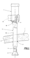
- Fig. 1 there is shown schematically part of a cover 1 of a tank of a nuclear reactor pressurized water.
- the cover 1 is crossed by openings 2 inside each of which is fixed a guide tube designated as a whole by the reference 3 and which constitutes an adapter allowing the passage of an extension ensuring the movement of a reactivity control cluster inside the nuclear reactor vessel or the passage of a thermocouple column or mounting of a sealing plug of this guide tube 3 for introduction, after removing this plug, inspection means of inside the tank.
- the guide tube 3 of generally tubular shape comprises a cylindrical body 3a whose diameter corresponds to diameter of opening 2 and which is fixed by an outline of annular weld 4 on the underside of the cover 1 so as to be salient with respect to this lower internal face.
- the guide tube 3 also includes a head 3b of diameter greater than the cylindrical body 3a, located at outside and above the cover 1.
- This head 3b is provided with an external thread 3c.
- a tubular thermal sleeve 5 is arranged coaxially inside the internal bore of the guide tube 3 and comprises, in the embodiment shown in Fig. 1, a lower part 6 of frustoconical shape.
- the extension movement control mechanism a core reactivity control cluster designated by the general reference 7 or a thermocouple column to measure the temperature inside of the tank or a closure cap is fixed on the head 3b of the guide tube 3 by screwing onto the threaded part 3c and supported on a lip seal 8 provided on the head 3b of said guide tube 3.
- Attaching the control mechanism or thermocouple column or blanking plug is completed by a bead of sealing weld ensuring the junction between the mechanism and the guide tube 3 along the lip seal 8.
- a mechanism for controlling the movement of the extender a control cluster or thermocouple column or a sealing plug is mounted on the head 3b of the guide tube 3 by means of a connection device in accordance with the invention and designated as a whole the reference 10.
- connection device shown in Figures 2 to 8 comprises of hand, a housing 20 adaptable to the head 3b of the guide tube 3 and provided with sealing means with said head 3b and, on the other part, means 40 for independent tightening of the casing 20 and exerting an application force of this casing 20 on the head 3b of said guide tip 3.
- the casing 20 has a peripheral rim 21 which determines, on the one hand, a bore 22 whose diameter roughly matches the outside diameter of the head 3b of the guide tube 3 and, on the other hand, an edge 23 forming a support for the clamping means 40, as will be seen later.
- the casing 20 is provided with sealing means with the head 3b of the guide tube 3 and which are formed by a seal 24 arranged in a housing 25 formed in the bottom of the casing 20.
- the seal 24 is applied against the upper face of said head 3b by the clamping means 40.
- the depth of the housing 25 for receiving the seal 24 is determined to limit crushing of this seal when mounting the casing 20 on the head 3b of the guide tube 3.
- the seal 24 is formed for example by a metal O-ring.
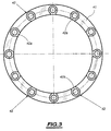
- the clamping means 40 of the casing 20 on the head 3b of the guide tube 3 include an upper flange 41 mounted on the edge 23 of the casing 20 and provided with orifices smooth 42 uniformly distributed on said upper flange 41.
- Each orifice 42 has an upper part formed by counterbore 42a emerging inside said upper flange 41, as shown in FIG. 3.
- the clamping means 40 also include a lower flange 43 provided, on the one hand, with an internal thread 43a cooperating with the external thread 3c of the head 3b of the guide tube 3 and, on the other hand, threaded orifices 43b.
- peripheral edge 21 of the casing 20 has counterbores 21a opening outwards of said peripheral edge and uniformly distributed, as shown in Fig. 4.
- the number of threaded holes 43b on the flange lower 43 is equal to the number of counterbores 21 formed on the peripheral edge 21 of the casing 20 and the number of orifices rails 42 of upper flange 41.
- the flanges 41 and 43 are interconnected by connecting members constituted by screwing elements 44 which are each mounted in a smooth orifice 42 of the upper flange 41 and whose threaded end 44a is screwed into a threaded hole 43b of the lower flange 43.
- Each screw element 44 also passes through a counterbore 21a of the casing 20.
- the mounting of the casing 20 and the clamping means 40 is carried out as follows.
- the lower flange 43 is screwed on the threaded part 3c of the head 3b of the guide tube 3 and the casing 20 provided with the seal 24 is placed on said head 20.
- the upper flange 41 is mounted on the edge 21 of the housing 20.
- Each screw element 44 is mounted in a smooth orifice 42 of the upper flange 41, passes through a countersink 21a of said casing 20 and is screwed into a threaded orifice 43b of the lower flange 43.
- the casing 20 is identical to the casing of the previous embodiment and comprises also a housing 25 for receiving the seal 24 as well as a peripheral edge 21 provided with counterbores 21a.
- the clamping means 40 are formed by a upper flange 41 provided with smooth orifices 42 which include each an upper part formed by counterbores 42a opening into the interior of said upper crown 41.
- the clamping means 40 also include a lower flange 45 provided with threaded holes 45a uniformly distributed and whose number is equal to the number smooth orifices 42 formed in the upper flange 41.
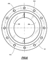
- This lower ring 45 has a bore internal 46 whose diameter is greater than the diameter external of the head 3b of the guide tube 3.
- the lower flange 45 has a flange internal 47 forming a bearing surface for two half-shells, respectively 48a and 48b (Fig. 6), arranged around of body 3a of guide tube 3 and below head 3b of said guide tube 3, as shown in FIG. 5.
- each half-crown 48a and 48b is of complementary shape to the profile of the wall of connection between the body 3a and the head 3b of the guide tube 3.
- the flanges 41 and 45 are interconnected by connecting members 49 constituted, by elements of screws 49 each mounted in a smooth hole 42 of the upper flange 41 and of which the threaded end 49a is screwed in a tapped hole 45a of the lower flange 45.
- the mounting of the clamping means 40 is, in this embodiment, carried out as follows.
- the lower flange 45 is introduced on the body 3a of the guide tube 3 and each half-crown 48a and 48b is placed on the internal rim 47 of the lower flange 45.
- the casing 20 provided with a seal 24 is arranged on the head 3b of the guide tube 3 and the flange upper 41 is mounted on the peripheral rim 41 of this housing 20.
- the assembly constituted by the lower flange 45 and the two half-crowns 48a and 48b is lifted by suitable means for these half-crowns 48a and 48b are applied below the head 3b of the guide tube 3.
- Each screw element 49 is mounted in a smooth orifice 42 of the upper flange 41, passes through a countersink 21a of the casing 20 and is screwed into a tapped hole 45a of the lower flange 45.
- the screwing of the elements 49 makes it possible to exercise a application force of the casing 20 on the head 3b of the tube guide 3 and compress the seal 24 to ensure sealing.
- the crushing of this seal 24 is limited by the depth of the housing 25 for receiving said seal.
- Figs. 7 and 8 we will describe a third embodiment of the means 40 of tightening of the casing 20 on the head 3b of the guide tube 3.
- the casing 20 is identical to the casing of the previous embodiments and comprises a seal 24 and the clamping means 40 are identical to the clamping means of the embodiment shown in Fig. 5.
- an additional seal to that performed by the main seal 24 is obtained by an additional seal 55 arranged on the lateral face of the head 3b of the guide tube 3.
- This complementary seal 55 is formed for example by a metal O-ring.
- the main seal 24 and the complementary seal 55 are applied respectively on the upper side and the lateral side of the head 3b of the guide tube 3 by the clamping means 40.
- clamping means 40 are associated to means for applying the additional seal 55 simultaneously on the lateral face of the head 3b of the tube guide 3 and on the underside of the housing 20.
- means for applying the secondary seal 55 include a crown 56 arranged below the casing 20 and maintained on the underside of said housing by nuts 60 screwed each on a screwing element 49 connecting the upper flanges 41 and lower 45.
- peripheral rim 21 of the housing 20 household, with the upper part of the head 3b of the guide tube 3, a space 57 whose bottom formed by the lower wall of the casing 20 is inclined and in which the additional seal 55 is positioned.
- the crown 56 has a first part 56a forming a flange intended to be applied to the underside of the casing 20 and a second part 56b in the form of collar and inclined towards the axis of the guide tube 3.
- This second part 56b penetrates into space 57 formed between the head 3b of the guide tube 3 and the peripheral rim 21 of housing 20.
- the collar 56b of the crown 56 determines with the side face of the head 3b of the guide tube 3 and the face bottom of the casing 20, a housing 57a of triangular shape for additional seal 55.
- the upper face collar 56b determines with the underside of the casing 20 a clearance "j" which makes it possible to compress the complementary seal 55 on the lateral face of the head 3b of the tube guide 3 and, therefore, to perform an additional seal compared to that already achieved by the joint main 24.
- channel 59 is formed in the rim 21 of the casing 20 in order to be able to produce a check of the tightness of the seals 24 and 55.
- the connecting members are formed by screwing elements 44 each passing through a smooth orifice 42 formed in the upper flange 41 and a smooth orifice 43c formed in the lower flange 43.
- a nut 44b is screwed on the end threaded 44a of each screwing element 44.
- Spring washers 60 are interposed between the nut 44b of each screwing element 44 and the flange lower 43.
- the connecting members are formed by elements of screwing 49 each passing through a smooth orifice 42 formed in the upper flange 41 and a smooth orifice 45b formed in the lower flange 45.
- a nut 49b is screwed onto the end threaded 49a of each screwing element 49.
- Spring washers 60 are interposed between the nut 49b of each screwing element 49 and the flange lower 45.
- the washers elastic 60 can be interposed between the head of each screwing element 44 or 49 and the bottom of the counterbore 42a of the smooth orifice 42 of the upper flange 41.
- the elastic washers 60 allow the recovery differential expansions between the elements of screwing and the body of the guide tube and also power adjust the clamping force by calculating the height of stacking these washers.
- the housing 20 is formed by a housing of a mechanism control cluster or column replacement thermocouple.
- This housing can be constituted by a sealing plug.
- connection device allows the mounting of a control mechanism of the clusters of control or thermocouple column or plug replacement shutter, the time required for remanufacturing lip seal, and has all the guarantees tightness during this replacement period.
Landscapes
- Physics & Mathematics (AREA)
- Engineering & Computer Science (AREA)
- Plasma & Fusion (AREA)
- General Engineering & Computer Science (AREA)
- High Energy & Nuclear Physics (AREA)
- Monitoring And Testing Of Nuclear Reactors (AREA)
- Infusion, Injection, And Reservoir Apparatuses (AREA)
- Gasket Seals (AREA)
Applications Claiming Priority (2)
| Application Number | Priority Date | Filing Date | Title |
|---|---|---|---|
| FR9903168A FR2791169B1 (fr) | 1999-03-15 | 1999-03-15 | Dispositif de raccordement d'un tube guide de couvercle d'une cuve de reacteur nucleaire a eau sous pression |
| FR9903168 | 1999-03-15 |
Publications (1)
| Publication Number | Publication Date |
|---|---|
| EP1037215A1 true EP1037215A1 (de) | 2000-09-20 |
Family
ID=9543199
Family Applications (1)
| Application Number | Title | Priority Date | Filing Date |
|---|---|---|---|
| EP00400523A Withdrawn EP1037215A1 (de) | 1999-03-15 | 2000-02-25 | Vorrichtung zum Anschliessen an ein Führungsrohr des Deckels eines Druckwasserkernreaktordruckbehälters |
Country Status (6)
| Country | Link |
|---|---|
| EP (1) | EP1037215A1 (de) |
| KR (1) | KR20010111275A (de) |
| CN (1) | CN1343361A (de) |
| FR (1) | FR2791169B1 (de) |
| TW (1) | TW454206B (de) |
| WO (1) | WO2000055864A1 (de) |
Cited By (2)
| Publication number | Priority date | Publication date | Assignee | Title |
|---|---|---|---|---|
| FR3025932A1 (fr) * | 2014-09-16 | 2016-03-18 | Areva Np | Procede de maintenance d'un ensemble d'instrumentation interne de reacteur nucleaire |
| WO2017116680A1 (en) * | 2015-12-29 | 2017-07-06 | Ge-Hitachi Nuclear Energy Americas Llc | Reactor pressure vessel including pipe restraint device, and/or a pipe restraint device |
Families Citing this family (3)
| Publication number | Priority date | Publication date | Assignee | Title |
|---|---|---|---|---|
| JP4599410B2 (ja) | 2007-02-28 | 2010-12-15 | 三菱重工業株式会社 | 計装案内管流動振動抑制構造 |
| CN103440885B (zh) * | 2013-08-28 | 2016-03-02 | 中国核动力研究设计院 | 探测器用密封结构及反应堆密封容器 |
| US11380447B2 (en) * | 2020-05-26 | 2022-07-05 | Westinghouse Electric Company Llc | Method for installing extension tube in a nuclear reactor |
Citations (9)
| Publication number | Priority date | Publication date | Assignee | Title |
|---|---|---|---|---|
| US3861722A (en) * | 1973-07-31 | 1975-01-21 | Coupco Ltd | Flange adaptor |
| GB2060803A (en) * | 1979-10-18 | 1981-05-07 | Tungum Hydraulics Ltd | Improvements in or relating to pipe couplings |
| EP0164524A1 (de) * | 1984-05-14 | 1985-12-18 | Combustion Engineering, Inc. | Grenzdichtung für Eindringen in ein Gefäss |
| GB2170562A (en) * | 1985-02-05 | 1986-08-06 | Westinghouse Electric Corp | Axial clamp for nuclear reactor head penetration conoseal joints |
| GB2200702A (en) * | 1987-01-28 | 1988-08-10 | Pipe Line Development Co | Coupling plain pipe ends |
| DE9015457U1 (de) * | 1990-11-02 | 1991-04-25 | Parker-Ermeto GmbH, 4800 Bielefeld | Verbindungssystem |
| US5050913A (en) * | 1989-01-09 | 1991-09-24 | Erwin Lenz | High pressure, rotatable pipe joints |
| WO1995027287A1 (fr) * | 1994-03-31 | 1995-10-12 | Framatome | Dispositif d'etancheite pour une colonne d'instrumentation |
| US5619546A (en) * | 1995-04-20 | 1997-04-08 | Combustion Engineering, Inc. | Resistance temperature detector nozzle mechanical clamp |
-
1999
- 1999-03-15 FR FR9903168A patent/FR2791169B1/fr not_active Expired - Fee Related
-
2000
- 2000-02-25 CN CN00805067A patent/CN1343361A/zh active Pending
- 2000-02-25 KR KR1020017011695A patent/KR20010111275A/ko not_active Withdrawn
- 2000-02-25 WO PCT/FR2000/000475 patent/WO2000055864A1/fr not_active Ceased
- 2000-02-25 EP EP00400523A patent/EP1037215A1/de not_active Withdrawn
- 2000-03-01 TW TW089103610A patent/TW454206B/zh not_active IP Right Cessation
Patent Citations (9)
| Publication number | Priority date | Publication date | Assignee | Title |
|---|---|---|---|---|
| US3861722A (en) * | 1973-07-31 | 1975-01-21 | Coupco Ltd | Flange adaptor |
| GB2060803A (en) * | 1979-10-18 | 1981-05-07 | Tungum Hydraulics Ltd | Improvements in or relating to pipe couplings |
| EP0164524A1 (de) * | 1984-05-14 | 1985-12-18 | Combustion Engineering, Inc. | Grenzdichtung für Eindringen in ein Gefäss |
| GB2170562A (en) * | 1985-02-05 | 1986-08-06 | Westinghouse Electric Corp | Axial clamp for nuclear reactor head penetration conoseal joints |
| GB2200702A (en) * | 1987-01-28 | 1988-08-10 | Pipe Line Development Co | Coupling plain pipe ends |
| US5050913A (en) * | 1989-01-09 | 1991-09-24 | Erwin Lenz | High pressure, rotatable pipe joints |
| DE9015457U1 (de) * | 1990-11-02 | 1991-04-25 | Parker-Ermeto GmbH, 4800 Bielefeld | Verbindungssystem |
| WO1995027287A1 (fr) * | 1994-03-31 | 1995-10-12 | Framatome | Dispositif d'etancheite pour une colonne d'instrumentation |
| US5619546A (en) * | 1995-04-20 | 1997-04-08 | Combustion Engineering, Inc. | Resistance temperature detector nozzle mechanical clamp |
Cited By (4)
| Publication number | Priority date | Publication date | Assignee | Title |
|---|---|---|---|---|
| FR3025932A1 (fr) * | 2014-09-16 | 2016-03-18 | Areva Np | Procede de maintenance d'un ensemble d'instrumentation interne de reacteur nucleaire |
| WO2017116680A1 (en) * | 2015-12-29 | 2017-07-06 | Ge-Hitachi Nuclear Energy Americas Llc | Reactor pressure vessel including pipe restraint device, and/or a pipe restraint device |
| US10473255B2 (en) | 2015-12-29 | 2019-11-12 | Ge-Hitachi Nuclear Energy Americas Llc | Reactor pressure vessel including pipe restraint device, and/or a pipe restraint device |
| US11530769B2 (en) | 2015-12-29 | 2022-12-20 | Ge-Hitachi Nuclear Energy Americas Llc | Reactor pressure vessel including pipe restraint device, and/or pipe restraint device |
Also Published As
| Publication number | Publication date |
|---|---|
| WO2000055864A1 (fr) | 2000-09-21 |
| FR2791169B1 (fr) | 2001-12-07 |
| KR20010111275A (ko) | 2001-12-17 |
| FR2791169A1 (fr) | 2000-09-22 |
| CN1343361A (zh) | 2002-04-03 |
| TW454206B (en) | 2001-09-11 |
Similar Documents
| Publication | Publication Date | Title |
|---|---|---|
| EP0041014B1 (de) | Befestigungsanordnung für ein Führungsrohr eines Brennelementenbündels auf die Endplatten dieses Bündels | |
| EP2376827B1 (de) | Abgedichtete stopfenanordnung für eine öffnung in einem verbindungsrohr zwischen einem gehäuse und einer rohrleitung sowie verfahren zum einsetzen dieser anordnung. | |
| CA2123379A1 (fr) | Equipement interne pour le soudage bout a bout par faisceau d'electrons de deux pieces annulaires et utilisation | |
| EP1037215A1 (de) | Vorrichtung zum Anschliessen an ein Führungsrohr des Deckels eines Druckwasserkernreaktordruckbehälters | |
| EP0577453B1 (de) | Verfahren zum Einsatz eines Instrumentierungsrohres eines Druckreaktorkernreaktors und Vorrichtung zum Verändern der axialen Lagen des Rohres | |
| EP0701260B1 (de) | Dichtvorrichtung für ein innerhalb eines Adapters durch den Deckel eines Kernreaktorgefässes führendes Instrumentenführungsrohr | |
| EP0751531B1 (de) | Verbindungselement für eine Vorrichtung zur Messung wenigstens eines physikalischen Parameters innerhalb des Kerns eines nuklearen Reaktors | |
| FR2748566A1 (fr) | Dispositif de prise d'echantillon sur une canalisation | |
| FR2689297A1 (fr) | Procédé de démontage et de remplacement d'une manchette thermique d'une traversée d'un couvercle de cuve d'un réacteur nucléaire à eau sous pression et manchette thermique démontable de remplacement. | |
| EP0428433B1 (de) | Vorrichtung zum Fixieren der Steuerstabsführungsplatte im Kernreaktordruckgefäss | |
| EP0263733B1 (de) | Vorrichtung zum dichten Verschliessen einer Wanddurchführung | |
| FR2642217A1 (fr) | Dispositif d'etancheite pour une colonne d'instrumentation traversant le couvercle d'une cuve de reacteur nucleaire a eau sous pression | |
| BE1008091A6 (fr) | Dispositif d'etancheite pour une colonne d'instrumentation traversant le couvercle d'une cuve de reacteur nucleaire. | |
| FR2718276A1 (fr) | Dispositif d'étanchéité pour une colonne d'instrumentation. | |
| FR2859308A1 (fr) | Dispositif de deplacement d'une barre de commande d'un reacteur nucleaire a eau sous pression et procede de montage du dispositif sur un couvercle de cuve | |
| EP0349379A1 (de) | Regelspinne mit demortierbaren Stäben für ein Kernbrennstabbündel | |
| LU85226A1 (fr) | Bouteille en acier pour un appareil a boissons | |
| BE1009655A3 (fr) | Procede et dispositif de fermeture etanche d'un conduit tubulaire d'instrumentation d'un reacteur nucleaire. | |
| EP0426519B1 (de) | Abdichtungsvorrichtung einer vertikalen Rohrleitung, die ein längliches Element trägt und leitet | |
| BE1007692A3 (fr) | Dispositif auxiliaire de relachement commande a distance pour un mecanisme a action positive. | |
| FR2690001A1 (fr) | Bouchon étanche pour trou taraudé. | |
| FR2676514A1 (fr) | Assemblage visse de securite de deux pieces et dispositifs de realisation et de mise en óoeuvre d'un tel assemblage. | |
| FR2571118A1 (fr) | Organe de fermeture etanche pour une piece de raccordement ou un element de connexion similaire dans une canalisation pour liquide ou gaz sur un reservoir | |
| WO2005062312A2 (fr) | Systeme d'etancheite d'une colonne d'instrumentation traversant un couvercle d'une enceinte sous pression et procede de montage et de demontage d'un tel systeme d'etancheite | |
| FR2832216A1 (fr) | Procede et dispositif de controle d'une portee d'etancheite d'un ensemble tubulaire et utilisation |
Legal Events
| Date | Code | Title | Description |
|---|---|---|---|
| PUAI | Public reference made under article 153(3) epc to a published international application that has entered the european phase |
Free format text: ORIGINAL CODE: 0009012 |
|
| AK | Designated contracting states |
Kind code of ref document: A1 Designated state(s): BE CH ES FR GB LI SE |
|
| AX | Request for extension of the european patent |
Free format text: AL;LT;LV;MK;RO;SI |
|
| K1C3 | Correction of patent application (complete document) published |
Effective date: 20000920 |
|
| RTI1 | Title (correction) |
Free format text: DEVICE FOR CONNECTING A GUIDE PIPE IMPLEMENTED ON A PRESSURIZED WATER NUCLEAR REACTOR VESSEL HEAD |
|
| 17P | Request for examination filed |
Effective date: 20010305 |
|
| AKX | Designation fees paid |
Free format text: BE CH ES FR GB LI SE |
|
| AXX | Extension fees paid |
Free format text: SI PAYMENT 20010305 |
|
| REG | Reference to a national code |
Ref country code: DE Ref legal event code: 8566 |
|
| STAA | Information on the status of an ep patent application or granted ep patent |
Free format text: STATUS: THE APPLICATION HAS BEEN WITHDRAWN |
|
| 17Q | First examination report despatched |
Effective date: 20021122 |
|
| 18W | Application withdrawn |
Effective date: 20021207 |