EP1037331A1 - Bôite perfectionnée pour socle de prise de courant - Google Patents
Bôite perfectionnée pour socle de prise de courant Download PDFInfo
- Publication number
- EP1037331A1 EP1037331A1 EP00400713A EP00400713A EP1037331A1 EP 1037331 A1 EP1037331 A1 EP 1037331A1 EP 00400713 A EP00400713 A EP 00400713A EP 00400713 A EP00400713 A EP 00400713A EP 1037331 A1 EP1037331 A1 EP 1037331A1
- Authority
- EP
- European Patent Office
- Prior art keywords
- box
- fixing
- positions
- screwing
- orifice
- Prior art date
- Legal status (The legal status is an assumption and is not a legal conclusion. Google has not performed a legal analysis and makes no representation as to the accuracy of the status listed.)
- Withdrawn
Links
- 230000002093 peripheral effect Effects 0.000 abstract 1
- 238000009434 installation Methods 0.000 description 5
- 238000004873 anchoring Methods 0.000 description 3
- 230000008878 coupling Effects 0.000 description 3
- 238000010168 coupling process Methods 0.000 description 3
- 238000005859 coupling reaction Methods 0.000 description 3
- 238000010616 electrical installation Methods 0.000 description 2
- 230000015572 biosynthetic process Effects 0.000 description 1
- 239000004020 conductor Substances 0.000 description 1
- 238000005755 formation reaction Methods 0.000 description 1
- 238000010348 incorporation Methods 0.000 description 1
- 238000003780 insertion Methods 0.000 description 1
- 230000037431 insertion Effects 0.000 description 1
Images


Classifications
-
- H—ELECTRICITY
- H02—GENERATION; CONVERSION OR DISTRIBUTION OF ELECTRIC POWER
- H02G—INSTALLATION OF ELECTRIC CABLES OR LINES, OR OF COMBINED OPTICAL AND ELECTRIC CABLES OR LINES
- H02G3/00—Installations of electric cables or lines or protective tubing therefor in or on buildings, equivalent structures or vehicles
- H02G3/02—Details
- H02G3/08—Distribution boxes; Connection or junction boxes
- H02G3/12—Distribution boxes; Connection or junction boxes for flush mounting
- H02G3/121—Distribution boxes; Connection or junction boxes for flush mounting in plain walls
-
- H—ELECTRICITY
- H02—GENERATION; CONVERSION OR DISTRIBUTION OF ELECTRIC POWER
- H02G—INSTALLATION OF ELECTRIC CABLES OR LINES, OR OF COMBINED OPTICAL AND ELECTRIC CABLES OR LINES
- H02G3/00—Installations of electric cables or lines or protective tubing therefor in or on buildings, equivalent structures or vehicles
- H02G3/02—Details
- H02G3/08—Distribution boxes; Connection or junction boxes
- H02G3/18—Distribution boxes; Connection or junction boxes providing line outlets
Definitions
- Sockets for sockets that can be installed in installations electrical for the function of what we know as connections, conventionally include a housing for elements of electrical connection, on which an embellished cover and protection, while the whole assembly mates in assembly with respect to a fixing frame which can be embedded or applied at the place of the installation.
- the housing for the electrical connection elements is made in a shape that allows coupling in different mounting positions relative to the fixing frame, the box mentioned being provided with formations for coupling the cover and for fixing relative to the support structure by snaps elastic.
- a box for the socket outlets mentioned, of the positioning type variable in assembly being provided however in a form such that it be adaptable to its application with covers and structures classic support, being able to be placed also in a selective way in the montage.
- This box object of the invention determines a background with housings for the electrical connection terminals and for an earth terminal, with covering of said bottom by means of an inner cover which closes the housings, however it forms centrally across the whole a double through hole whose conduits correspond to the mooring fixing by screwing in the respective positions of the situation selective angle of the box in the assembly.
- the box is also adaptable in the different mounting positions in its application with covers covering and conventional fixing structures, since the double through hole through the central area allows the insertion of the element of fixing in the appropriate correspondence with the screw coupling in each of the selective mounting positions in the installation.
- Figure 1 shows an exploded perspective of the whole of the recommended box.
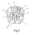
- Figure 2 is a perspective view from the top of the whole of the assembled box.
- Figure 3 is an enlarged sectional view of said recommended box.
- the object of the invention relates to a box for socket outlet current of the type of those which one poses for the connections by connection in electrical installations.
- Said box consists of a box body (1) defining a bottom (2) in which are defined housings for the respective terminals (3) of the electrical connection and for an earth terminal (4), which can be operated, to establish the connection and disconnection of cables, by means of pressure controls (5) which are located outside.
- the bottom (2) closes at the top with a cover interior (6) which covers the housing of the terminals (3) and (4), establishing in at the same time, by means of legs (7) projecting from its underside, the non-removable fixing of said terminals (3) and (4) in their positioning.
- the box body (1) additionally determines in the wall of the contour upper recesses (8) for snap-fastening of a cover corresponding closing cover, while in this same wall, flexible legs (9) are defined, by means of which the fixing on an anchoring frame, the box can be incorporated in different mounting positions in relation to the mentioned frame, thanks to respective sets of legs (9) located in two angular positions different.
- an orifice (10) which, according to the invention, is determined so double, with conduits (10.1) and (10.2) parallel but out of phase.
- the box can be positioned in a way that coincides with the fixing anchor by screwing with respect to a structure of classic fixing, in the two placement positions in the assembly, since, in one of the positions, it coincides with the screw anchoring of the conduit (10.1) while, in the other angular mounting position, it coincides with said screw anchor of the other conduit (10.2).
- the box can be adapted to the connection bases of electrical installations already carried out, bringing the versatility of the mounting position, for placement in the position revealed most suitable for inserting the connection pins.
- the orifice (10) is obviously traversing in its turn through the element conductor (11) of terminal (4) for earth connection, also passing to through the inner cover (6) which covers the terminal housings (3) and (4), elements in which the double conduit (10.1) and (10.2) can be at its tower defined independently or as a single orifice (10) widened transversely, in the dimension which corresponds to all of the two conduits (10.1) and (10.2).
Landscapes
- Engineering & Computer Science (AREA)
- Architecture (AREA)
- Civil Engineering (AREA)
- Structural Engineering (AREA)
- Connector Housings Or Holding Contact Members (AREA)
- Connection Or Junction Boxes (AREA)
Abstract
Description
Claims (1)
- Boíte perfectionnée pour socle de prise de courant, du type formé par un corps de boíte (1) avec un fond (2) dans lequel sont définis des logements pour les bornes (3) et (4) de connexion électrique et de prise de terre, cette boíte (1) pouvant se monter dans deux positions angulaires différentes, caractérisée en ce qu'à travers le fond (2) est défini en position centrale un orifice (10), pour la fixation par vissage de la boíte (1) sur un support classique, ledit orifice étant déterminé par des conduits (10.1) et (10.2) parallèles mais déphasés, dont le conduit (10.1) coïncide avec l'orifice de vissage du support classique correspondant dans l'une des deux positions angulaires de la boíte (1) ; tandis que le conduit (10.2) coïncide dans l'autre position angulaire, en permettant d'établir la fixation de la boíte (1) par vissage dans l'une quelconque des deux positions.
Applications Claiming Priority (2)
| Application Number | Priority Date | Filing Date | Title |
|---|---|---|---|
| ES9900656 | 1999-03-15 | ||
| ES9900656U ES1042328Y (es) | 1999-03-15 | 1999-03-15 | Caja perfeccionada para base toma-corriente. |
Publications (1)
| Publication Number | Publication Date |
|---|---|
| EP1037331A1 true EP1037331A1 (fr) | 2000-09-20 |
Family
ID=8307861
Family Applications (1)
| Application Number | Title | Priority Date | Filing Date |
|---|---|---|---|
| EP00400713A Withdrawn EP1037331A1 (fr) | 1999-03-15 | 2000-03-15 | Bôite perfectionnée pour socle de prise de courant |
Country Status (3)
| Country | Link |
|---|---|
| EP (1) | EP1037331A1 (fr) |
| ES (1) | ES1042328Y (fr) |
| RU (1) | RU2000106429A (fr) |
Cited By (3)
| Publication number | Priority date | Publication date | Assignee | Title |
|---|---|---|---|---|
| EP1667298A1 (fr) * | 2004-12-01 | 2006-06-07 | Alombard SAS | Socle de prise de courant |
| EP1675238A1 (fr) * | 2004-12-23 | 2006-06-28 | Abb B.V. | Boîte électrique avec moyens de fixation |
| EP2775580A1 (fr) * | 2013-03-08 | 2014-09-10 | Legrand France | Support d'appareillage électrique et appareillage électrique comprenant un tel support |
Families Citing this family (1)
| Publication number | Priority date | Publication date | Assignee | Title |
|---|---|---|---|---|
| ITMI20050903A1 (it) * | 2005-05-17 | 2006-11-18 | Bticino Spa | Quadro elettrico da incasso |
Citations (3)
| Publication number | Priority date | Publication date | Assignee | Title |
|---|---|---|---|---|
| DE2552005A1 (de) * | 1975-11-20 | 1977-05-26 | Bbc Brown Boveri & Cie | Elektrisches installationsgeraet mit einem tragorgan fuer unterputz- einrichtungen o.dgl. |
| DE3743557A1 (de) * | 1987-12-22 | 1989-07-13 | Asea Brown Boveri | Befestigungssystem fuer geraetesockel |
| WO1996011518A1 (fr) * | 1994-10-10 | 1996-04-18 | Thorsman & Co. Ab | Chassis a emboitement |
-
1999
- 1999-03-15 ES ES9900656U patent/ES1042328Y/es not_active Expired - Fee Related
-
2000
- 2000-03-14 RU RU2000106429/09A patent/RU2000106429A/ru not_active Application Discontinuation
- 2000-03-15 EP EP00400713A patent/EP1037331A1/fr not_active Withdrawn
Patent Citations (3)
| Publication number | Priority date | Publication date | Assignee | Title |
|---|---|---|---|---|
| DE2552005A1 (de) * | 1975-11-20 | 1977-05-26 | Bbc Brown Boveri & Cie | Elektrisches installationsgeraet mit einem tragorgan fuer unterputz- einrichtungen o.dgl. |
| DE3743557A1 (de) * | 1987-12-22 | 1989-07-13 | Asea Brown Boveri | Befestigungssystem fuer geraetesockel |
| WO1996011518A1 (fr) * | 1994-10-10 | 1996-04-18 | Thorsman & Co. Ab | Chassis a emboitement |
Cited By (3)
| Publication number | Priority date | Publication date | Assignee | Title |
|---|---|---|---|---|
| EP1667298A1 (fr) * | 2004-12-01 | 2006-06-07 | Alombard SAS | Socle de prise de courant |
| EP1675238A1 (fr) * | 2004-12-23 | 2006-06-28 | Abb B.V. | Boîte électrique avec moyens de fixation |
| EP2775580A1 (fr) * | 2013-03-08 | 2014-09-10 | Legrand France | Support d'appareillage électrique et appareillage électrique comprenant un tel support |
Also Published As
| Publication number | Publication date |
|---|---|
| RU2000106429A (ru) | 2002-03-20 |
| ES1042328Y (es) | 2000-01-01 |
| ES1042328U (es) | 1999-08-16 |
Similar Documents
| Publication | Publication Date | Title |
|---|---|---|
| FR2816036A3 (fr) | Ensemble d'ampoule et d'adaptateur a douille pour lampe de fantaisie | |
| EP0434777A1 (fr) | Ensemble et systeme de fiches electriques. | |
| CA2031007A1 (fr) | Cadre pour meuble de bureau modulable dont les conducteurs electriques sont loges dans le plateau | |
| FR2777732A1 (fr) | Agencement de connexion electrique | |
| FR2633369A1 (fr) | Perfectionnement aux systemes de fixation en connexion rapide pour des lampes, en particulier des lampes ayant un boitier resistant aux intemperies | |
| WO2015103428A1 (fr) | Groupe de montage de dispositif électrique | |
| EP1037331A1 (fr) | Bôite perfectionnée pour socle de prise de courant | |
| AU660517B2 (en) | Device for lighting and suspension of a hanging-rod and modular assembly for lighting and suspension of hanging-rods | |
| FR2835039A3 (fr) | Dispositif de montage rapide de tige de lampe et de douille de lampe | |
| FR2488064A1 (fr) | Element d'installation electrique tel qu'interrupteur, prise de courant ou analogue | |
| US6010346A (en) | Light bulb socket with water draining structure | |
| EP0315558A1 (fr) | Baguette électrifiée faisant office de glissière pour une prise électrique mobile | |
| FR2723480A1 (fr) | Cablage en serie d'ampoules electriques de noel et douille d'ampoule electrique a structure amelioree | |
| AU783167B2 (en) | Electrical cable junction box | |
| FR2812713A1 (fr) | Galerie d'eclairage pour enceinte contenant un milieu humide | |
| EP0680109B1 (fr) | Embase d'antenne ayant un écrou porté par un support muni de moyens de montage unidirectionnel | |
| JP2537961Y2 (ja) | 電磁弁用端子箱装置 | |
| JPH0210731Y2 (fr) | ||
| WO2005112204A1 (fr) | Enceinte electrique a mecanisme de verrouillage rotatif et procedes de montage et de demontage associes | |
| EP1002345B1 (fr) | Boitier de connexion electrique | |
| FR2660020A1 (fr) | Dispositif d'allumage pour moteur a combustion interne. | |
| FR2761139A1 (fr) | Embase de fixation d'un luminaire de rue ou appareil similaire a un mur | |
| JPH11243629A (ja) | 電源ポール | |
| KR100817176B1 (ko) | 전기 통신선의 분기구 | |
| EP1481194A1 (fr) | Douille electrique pour luminaires d'exterieur |
Legal Events
| Date | Code | Title | Description |
|---|---|---|---|
| PUAI | Public reference made under article 153(3) epc to a published international application that has entered the european phase |
Free format text: ORIGINAL CODE: 0009012 |
|
| AK | Designated contracting states |
Kind code of ref document: A1 Designated state(s): AT BE CH CY DE DK ES FI FR GB GR IE IT LI LU MC NL PT SE |
|
| AX | Request for extension of the european patent |
Free format text: AL;LT;LV;MK;RO;SI |
|
| 17P | Request for examination filed |
Effective date: 20010315 |
|
| AKX | Designation fees paid |
Free format text: AT BE CH CY DE DK ES FI FR GB GR IE IT LI LU MC NL PT SE |
|
| GRAP | Despatch of communication of intention to grant a patent |
Free format text: ORIGINAL CODE: EPIDOSNIGR1 |
|
| RIN1 | Information on inventor provided before grant (corrected) |
Inventor name: LEGARIA BENITO, ANTONIO |
|
| STAA | Information on the status of an ep patent application or granted ep patent |
Free format text: STATUS: THE APPLICATION IS DEEMED TO BE WITHDRAWN |
|
| 18D | Application deemed to be withdrawn |
Effective date: 20071003 |