EP1037378A2 - Verfahren und Vorrichtung zur Adaption des Systemparameters Rotorwiderstand einer drehgeberlosen, feldorientiert betriebenen Drehfeldmaschine - Google Patents
Verfahren und Vorrichtung zur Adaption des Systemparameters Rotorwiderstand einer drehgeberlosen, feldorientiert betriebenen Drehfeldmaschine Download PDFInfo
- Publication number
- EP1037378A2 EP1037378A2 EP00104102A EP00104102A EP1037378A2 EP 1037378 A2 EP1037378 A2 EP 1037378A2 EP 00104102 A EP00104102 A EP 00104102A EP 00104102 A EP00104102 A EP 00104102A EP 1037378 A2 EP1037378 A2 EP 1037378A2
- Authority
- EP
- European Patent Office
- Prior art keywords
- stator
- input
- rotor resistance
- torque difference
- reactive torque
- Prior art date
- Legal status (The legal status is an assumption and is not a legal conclusion. Google has not performed a legal analysis and makes no representation as to the accuracy of the status listed.)
- Granted
Links
Images


Classifications
-
- H—ELECTRICITY
- H02—GENERATION; CONVERSION OR DISTRIBUTION OF ELECTRIC POWER
- H02P—CONTROL OR REGULATION OF ELECTRIC MOTORS, ELECTRIC GENERATORS OR DYNAMO-ELECTRIC CONVERTERS; CONTROLLING TRANSFORMERS, REACTORS OR CHOKE COILS
- H02P21/00—Arrangements or methods for the control of electric machines by vector control, e.g. by control of field orientation
- H02P21/24—Vector control not involving the use of rotor position or rotor speed sensors
- H02P21/28—Stator flux based control
-
- H—ELECTRICITY
- H02—GENERATION; CONVERSION OR DISTRIBUTION OF ELECTRIC POWER
- H02P—CONTROL OR REGULATION OF ELECTRIC MOTORS, ELECTRIC GENERATORS OR DYNAMO-ELECTRIC CONVERTERS; CONTROLLING TRANSFORMERS, REACTORS OR CHOKE COILS
- H02P21/00—Arrangements or methods for the control of electric machines by vector control, e.g. by control of field orientation
- H02P21/14—Estimation or adaptation of machine parameters, e.g. flux, current or voltage
- H02P21/16—Estimation of constants, e.g. the rotor time constant
-
- H—ELECTRICITY
- H02—GENERATION; CONVERSION OR DISTRIBUTION OF ELECTRIC POWER
- H02P—CONTROL OR REGULATION OF ELECTRIC MOTORS, ELECTRIC GENERATORS OR DYNAMO-ELECTRIC CONVERTERS; CONTROLLING TRANSFORMERS, REACTORS OR CHOKE COILS
- H02P21/00—Arrangements or methods for the control of electric machines by vector control, e.g. by control of field orientation
- H02P21/14—Estimation or adaptation of machine parameters, e.g. flux, current or voltage
- H02P21/18—Estimation of position or speed
Definitions
- the invention relates to a method for adapting the System parameters rotor resistance according to the preamble of the claim 1 and a device for adapting the system parameter Rotor resistance according to the preamble of claim 7.
- a generic method and a generic device are known from DE 196 46 457 A1. According to this Disclosure is in a predetermined frequency range the model stator frequency of the signal processing low-frequency modulated flow amount signal supplied. The The amplitude of this stator flux modulation is so determined that the one with the lowest value of the modulated Stator flux achievable torque still higher than that for example in the traction at these stator frequencies Maximum torque usually required at nominal stator flux is.
- the device for calculating a reactive torque difference which is downstream of the signal processing a switch connected downstream, on the one hand by means of a Compensation controller with one input of the system parameter stator resistance and on the other hand with a device for Peak value acquisition and a device for sign acquisition connected is.
- a second entrance to this facility for sign acquisition is with the output of the compensation regulator linked, the output side with an input of the Signal processing for the rotor model frequency is connected.
- the outputs of these two devices are each with one Input of a multiplier connected, the output side is linked to another compensation regulator.
- this is another compensation regulator with a Input of an adder connected to its second input a pre-control value for the rotor resistance adaptation is pending.
- This adder is on the output side with an input for signal processing linked for the system parameter rotor resistance.
- the determined reactive torque difference evaluated in terms of amplitude and phase, and then these results are linked together to form a manipulated variable to get for a PI controller.
- Also used for investigation of the manipulated variable is the sign of the phase shift angle between the reactive torque difference and the alternating component the identified speed. This is rotor resistance adaptation and speed identification at a predetermined frequency range of the model stator frequency coupled with each other.
- the invention is based on the object of a method and a device for adapting the rotor resistance system parameter an encoderless, field-oriented operated Indicate induction machine in which the aforementioned disadvantages no longer occur.
- the determined reactive torque difference and an ascertained stator flux amount and its ascertained mean value for determining a rotor resistance correction value used is the coupling between rotor resistance adaptation and speed identification interrupted.
- a method for adapting the system parameter is thus obtained Rotor resistance of an encoderless, field-oriented operated Induction machine independent of the operating state the induction machine works.
- FIG. 1 shows a block diagram of an embodiment of a device according to the invention, a major part of this embodiment being known from DE 196 46 457 A1.
- This known part of this device comprises a three-phase machine DM, which is fed by a pulse converter SR.
- a DC voltage 2E d also referred to as an intermediate circuit DC voltage, is present on the pulse converter SR on the input side.
- the pulse converter SR receives 2 control signals S a , S b , S c from signal processing.
- the known part of this device includes measuring elements 4, 6, 26, dead time elements 10, 12, 14, 16 and 28, a coordinate converter 8, a device 46 for calculating a reactive torque difference .DELTA..phi. And a compensation controller 22.
- the signal processing 2 is linked on the output side by means of the dead time element 10 to the pulse converter SR and by means of the dead time element 14 to an input of the device 46.
- the coordinate converter 8 is connected on the input side via the dead time element 12 to the measuring element 6 and on the output side to a further input of the device 46.
- the signal processing 2 is connected to the measuring element 26 and directly to the measuring element 4 by means of the dead time element 28.
- One output of the device 46, at which an effective torque difference ⁇ is present, is linked by means of a compensation regulator 22 to an input of the signal processing 2, whereas the other output of this device 46, at which a reactive torque difference ⁇ is present, by means of a multiplier 34 by one Input of a second compensation regulator 32 is connected, which is connected on the output side to an input of signal processing 2 for the system parameter stator resistance R ⁇ s .
- the device 46 for calculating an effective and reactive torque difference ⁇ and ⁇ have two multipliers 18 and 20 and two comparators 24 and 30.
- the outputs of the multiplier 18 are each with the non-inverting inputs of the two comparators 24 and 30 connected.
- the exits the multiplier 20 are each with the inverting Inputs of these two comparators 24 and 30 linked.
- the effective torque difference is at the output of the comparator 24 ⁇ on, with a reactive torque difference at the output of the comparator 30 ⁇ is pending.
- the signal processing 2 is preceded by a signal transmitter 50, at the input of which a value of a nominal stator flux 0 of the speed machine DM is pending.
- a signal transmitter 50 On the output side there is a low-frequency modulated flow amount signal according to the relationship: or according to the relationship is calculated. Which relationship is used in the signal generator 50 depends on whether the signal processor 2 can square or not.
- this known device has been supplemented by a changeover switch 52, an absolute value generator 54, an average value generator 56 and a device 58 for determining a rotor resistance correction value k r .
- the switch 52 is on the input side with the output of the device 46, on which the calculated reactive torque difference ⁇ is pending, and on the output side with an input of the Device 58 and on the other hand with an input of the multiplier 34 connected.
- the signal processing 2 supplies the amount generator 54 with a complex space pointer the stator flux chaining, whereas this signal processing 2 has a complex conjugate space pointer the stator flux chaining provides a second input of multipliers 18 and 20 of device 46, respectively.
- the amount generator 54 is connected on the one hand to the mean value generator 56 and on the other hand to the device 58 for determining a rotor resistance correction value k r .
- the averager 56 is also linked on the output side to an input of the device 58.
- An embodiment of this device 58 for determining a rotor resistance correction value k r is shown in more detail in FIG.
- the device 58 On the output side, the device 58 is linked to an input of the multiplier 60, at the second input of which there is a pilot control variable.
- the rotor resistance R r0 of the induction machine DM at the nominal point is selected as the pilot variable.
- this multiplier 60 On the output side, this multiplier 60 is connected to an input of signal processing 2 for the system parameter rotor resistance R ⁇ r .
- the signal processing 2 contains, among other things, a complete machine model and a modulator.
- 2 shows a block diagram of a complete machine model known from German laid-open publication 195 31 771.
- This complete machine model has multiple multipliers 70, 72, 74, 76, 78 and 80, two comparators 82 and 84, two adders 86 and 88 and two integrators 90 and 92.
- This complete machine model has two input variables, namely a converter output voltage space vector and an estimate ⁇ ⁇ of the angular velocity and the system parameters stator resistance R ⁇ s , rotor resistance R ⁇ r , magnetization inductance L ⁇ ⁇ and leakage inductance L ⁇ ⁇ are supplied.
- the complete machine model calculates the space pointers of the stator flux chaining from these default values (model sizes) the rotor flux chaining and the stator model current
- the stator current model space pointer is used for the calculation of switching variables S a , S b , S c by means of a modulator of the signal processing 2, which is not shown in detail, whereby the internal current-dependent voltage drops of the converter SR can be taken into account.
- FIG. 3 shows a block diagram of a device 58 for determining a rotor resistance correction value k r according to FIG. 1.
- This device 58 has two devices 94 and 96 on the input side for determining modulation-frequency alternating components and ⁇ ⁇ , which are each linked on the output side to an input of a multiplier 98.
- the device 58 has an integrating controller 100 on the output side, which is connected on the input side to an output of the multiplier 98 by means of a moving average filter 102.
- the device 94 for determining the modulation-frequency alternating component has a comparator 104.
- a determined stator flux amount is at the non-inverting input of this comparator 104 and a determined mean value at its inverting input of the stator flow amount on.
- the modulation-frequency alternating component is then at the output of this comparator 104 of the stator flow amount on.
- the determined mean is of the stator flow amount from the current stator flow amount subtracted.
- the mean value the mean value of the nominal function can be used with sufficient accuracy, so that a separate determination is unnecessary.
- the reactive torque difference ⁇ also contains a constant component at stator frequencies not equal to zero and existing speed difference ⁇ n ⁇ ⁇ . This is determined by means of a moving average filter 106, which determines the average over the duration of a modulation period. This DC component ⁇ ⁇ is subtracted from the determined reactive torque difference ⁇ by means of a further comparator 108, so that the modulation-frequency alternating component ⁇ ⁇ of the reactive torque difference ⁇ is present at the comparator 108 on the output side.
- the moving average filter 106 and the further comparator 108 are components of the device 96.
- the angle ⁇ denotes the phase shift between the alternating component ⁇ ⁇ , the reactive torque difference ⁇ and the modulation of the stator flow amount
- the exponent "s" denotes a peak value.
- the term cos ⁇ determines the sign of the DC component. It is positive if the model rotor resistance R ⁇ r ⁇ R r is assumed to be too small and the resulting in-phase nature of the alternating components is positive. If the model rotor resistance R ⁇ r > R r is assumed too large and the resulting phase opposition of the alternating components is negative.
- the alternating component of the determined product which oscillates at twice the modulation frequency, is suppressed in a second mean value filter 102, so that a signal is available which is a pure constant in steady-state operation with a constant rotor resistance difference.
- This constant quantity is used directly as an input signal of the subsequent integrating controller 100, at whose output a rotor resistance correction value k r is present. Since, due to the low-frequency test signal and the change in rotor resistance with the temperature, which is only slow in practice, the evaluation of the modulation-frequency reactive torque difference ⁇ has only a low dynamic range, a simple I controller is sufficient as an integrating controller 100.
- FIG. 4 shows a rotor resistance identification in stationary operation with a nominal torque in a diagram over time t.
- the related measured speed n of the induction machine DM is shown in this diagram for comparison. Since the value of the rotor resistance R ⁇ r in the model is initialized to approximately 50% of its actual value, the identified speed n ⁇ deviates from the speed n of the induction machine DM.
Landscapes
- Engineering & Computer Science (AREA)
- Power Engineering (AREA)
- Control Of Ac Motors In General (AREA)
- Control Of Eletrric Generators (AREA)
- Control Of Motors That Do Not Use Commutators (AREA)
- Tests Of Circuit Breakers, Generators, And Electric Motors (AREA)
Abstract

Description
- FIG 1
- zeigt ein Blockschaltbild einer Ausführungsform einer erfindungsgemäßen Vorrichtung, die
- FIG 2
- zeigt ein Blockschaltbild eines bekannten vollständigen Maschinenmodells, die
- FIG 3
- zeigt ein Blockschaltbild einer Ausführungsform einer Einrichtung zur Bestimmung eines Rotorwiderstand-Korrekturwertes und die
- FIG 4
- zeigt in einem Diagramm über die Zeit t die Rotorwiderstands-Adaption im stationären Betrieb mit Nominalmoment.

















Claims (11)
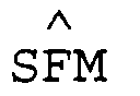
- Verfahren zur Adaption des Systemparameters Rotorwiderstand (R ∧r) einer drehgeberlosen, feldorientiert betriebenen Drehfeldmaschine (DM), wobei in Abhängigkeit eines Fluß-Sollwertes (), eines Drehmoment-Soliwertes (
 ), einer eingangsseitig am Pulsstromrichter (SR) der Drehfeldmaschine (DM) anstehenden Gleichspannung (2Ed), gemessener Stromrichter-Ausgangsspannungswerte (
e aM'e bM,e cM und Systemparameter (L ∧µ,L ∧σ,R ∧s,R ∧r/L ∧σ,ω ∧) ein Statorstrom-Modellraumzeigerund ein konjugiert komplexer Raumzeiger der Statorflußverkettung berechnet werden, wobei als Flußbetrags-Sollwert (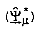
 eines ermittelten Statorstrom-Istraumzeigers (i s) und des berechneten konjugiert komplexen Raumzeigers
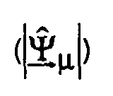
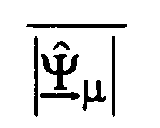
 der Statorflußverkettung eine Blindmomentdifferenz (Δ∥) ermittelt wird, dadurch gekennzeichnet, daß aus einem berechneten Statorfluß
 ein Statorflußbetrag
 und dessen Mittelwert
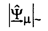
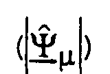 ermittelt wird und daß in Abhängigkeit der Blindmomentdifferenz (Δ∥), des Statorflußbetrages
 und seines Mittelwertes
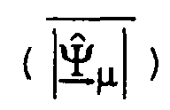 ein Rotorwiderstand-Korrekturwert (kr) bestimmt wird, der mit einem Vorsteuerwert (Rr0) des Systemparameters Rotorwiderstand (R ∧r) multipliziert wird.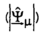
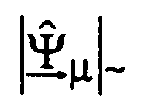
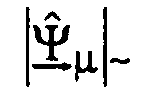
- Verfahren nach Anspruch 1, dadurch gekennzeichnet, daß zur Bestimmung des Rotorwiderstand-Korrekturwertes (kr) jeweils ein modulationsfrequenter Wechselanteil des Statorflußbetragesund der Blindmomentdifferenz (Δ∥∼) ermittelt werden, die miteinander multipliziert werden, und daß ein Wechselanteil des Produktsignals unterdrückt wird und der verbleibende Gleichanteil zu einem Rotorwiderstand-Korrekturwert (kr) auf integriert wird.

- Verfahren nach Anspruch 2, dadurch gekennzeichnet, zur Bestimmung eines modulationsfrequenten Wechselanteilsdes Statorflußbetrages
 der ermittelte Statorflußbetrag-Mittelwert
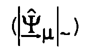 vom ermittelten Statorflußbetrag
 subtrahiert wird.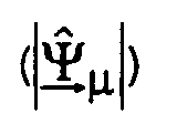
- Verfahren nach Anspruch 2, dadurch gekennzeichnet, daß zur Bestimmung einer modulationsfrequenten Blindmomentdifferenz (Δ∥∼) aus der ermittelten Blindmomentdifferenz (Δ∥) ein Mittelwert (
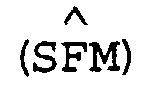
Δ ∥) gebildet wird, der anschließend von der ermittelten Blindmomentdifferenz (Δ∥) subtrahiert wird. - Verfahren nach einem der Ansprüche 1 bis 4, dadurch gekennzeichnet, daß das niederfrequent modulierte Flußbetragssignalnur zeitweise aufgeschaltet wird.
- Verfahren nach einem der Ansprüche 1 bis 5, dadurch gekennzeichnet, daß bei der Ermittlung einer Blindmomentdifferenz (Δ∥) anstelle von Statorstrom-Modellraumzeigerund -Istraumzeiger (i s) normierte Statorstrom-Modellraumzeiger
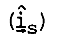 und -Istraumzeiger (y s) verwendet werden.
- Vorrichtung zur Adaption des Systemparameters Rotorwiderstand (R ∧r) einer drehgeberlosen, feldorientiert betriebenen Drehfeldmaschine (DM) mit einer Signalverarbeitung (2), die ein vollständiges Maschinenmodell und eine Einrichtung zur Generierung von Steuersignalen (Sa, Sb, Sc) enthält, mit einem Strommeßglied (6) mit nachgeschalteten Koordinatenwandler (8) und mit einem Signalgeber (50), an dessen Eingang ein Wert eines Nennstatorflusses (
 der Statorflußverkettung ansteht, dadurch gekennzeichnet, daß ein Betragsbildner (54) mit nachgeschaltetem Mittelwertbildner (56) und eine Einrichtung (58) zur Bestimmung eines Rotorwiderstand-Korrekturwertes (kr) vorgesehen sind, daß die Eingänge dieser Einrichtung (58) mit einem Ausgang des Betragsbildners (54), des Mittelwertbildners (56) und der Vorrichtung (46) verbunden sind, daß der Betragsbildner (54) eingangsseitig mit einem Ausgang der Signalverarbeitung (2), an dem ein Statorfluß-Raumzeiger
 ansteht, verknüpft ist und daß die Einrichtung (58) ausgangsseitg mit einem Eingang eines Multiplizierers (60) verbunden ist, mit dessen zweitem Eingang ein Vorsteuerwert (R ∧r0) des Systemparameters Rotorwiderstand (R ∧r) der Signalverarbeitung (2) verknüpft ist.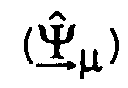
- Vorrichtung nach Anspruch 7, dadurch gekennzeichnet, daß die Vorrichtung (46) zur Berechnung einer Blindmomentdifferenz (Δ∥) zwei Multiplizierer (18,20) und zwei Vergleicher (24,30) aufweist, daß die ersten Ausgänge der beiden Multiplizierer (18,20) mit den Eingängen des ersten Vergleichers (24) und die zweiten Ausgänge der beiden Multiplizierer (18,20) mit den Eingängen des zweiten Vergleichers (30) verknüpft sind, daß die ersten Eingänge der beiden Multiplizierer (18,20) mit dem Ausgang der Signalverarbeitung (2) verbunden sind, an dem ein konjugiert komplexer Raumzeigerder Statorflußverkettung ansteht, und daß jeweils an einem zweiten Eingang der beiden Multiplizierer (18,20) entweder ein Statorstrom-Modellraumzeiger
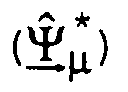 oder ein Statorstrom-Istraumzeiger (i s) ansteht.
- Vorrichtung nach Anspruch 7, dadurch gekennzeichnet, daß die Einrichtung (58) zur Bestimmung eines Rotorwiderstand-Korrekturwertes (kr) eingangsseitig zwei Einrichtungen (94,95) zur Ermittlung von modulationsfrequenten Wechselanteilendie ausgangsseitig jeweils mit einem Eingang eines Multiplizierers (98) verknüpft sind, und ausgangsseitig einen integrierenden Regler (100) aufweist, der eingangsseitig mittels eines gleitenden Mittelwertbildners (102) mit dem Ausgang des Multiplizierers (98) verbunden ist.

- Vorrichtung nach Anspruch 9, dadurch gekennzeichnet, daß als Einrichtung (94) zur Ermittlung eines modulationsfrequenten Wechselanteilsein Vergleicher (104) vorgesehen ist.

- Vorrichtung nach Anspruch 9, dadurch gekennzeichnet, daß als Einrichtung (96) zur Ermittlung eines modulationsfrequenten Wechselanteils (Δ∥∼) ein Vergleicher (108) mit einem gleitenden Mittelwertfilter (106) vorgesehen ist, dessen Eingang mit dem nichtinvertierenden Eingang des Vergleichers (108) und dessen Ausgang mit dem invertierenden Eingang des Vergleichers (108) verknüpft sind.
Applications Claiming Priority (2)
| Application Number | Priority Date | Filing Date | Title |
|---|---|---|---|
| DE19910609 | 1999-03-10 | ||
| DE19910609A DE19910609C2 (de) | 1999-03-10 | 1999-03-10 | Verfahren und Vorrichtung zur Adaption des Systemparameters Rotorwiderstand einer drehgeberlosen, feldorientiert betriebenen Drehfeldmaschine |
Publications (3)
| Publication Number | Publication Date |
|---|---|
| EP1037378A2 true EP1037378A2 (de) | 2000-09-20 |
| EP1037378A3 EP1037378A3 (de) | 2003-07-02 |
| EP1037378B1 EP1037378B1 (de) | 2007-08-08 |
Family
ID=7900432
Family Applications (1)
| Application Number | Title | Priority Date | Filing Date |
|---|---|---|---|
| EP00104102A Expired - Lifetime EP1037378B1 (de) | 1999-03-10 | 2000-02-28 | Verfahren und Vorrichtung zur Adaption des Systemparameters Rotorwiderstand einer drehgeberlosen, feldorientiert betriebenen Drehfeldmaschine |
Country Status (5)
| Country | Link |
|---|---|
| EP (1) | EP1037378B1 (de) |
| AT (1) | ATE369654T1 (de) |
| DE (2) | DE19910609C2 (de) |
| ES (1) | ES2288459T3 (de) |
| PT (1) | PT1037378E (de) |
Cited By (2)
| Publication number | Priority date | Publication date | Assignee | Title |
|---|---|---|---|---|
| FR2820902A1 (fr) * | 2001-02-14 | 2002-08-16 | Alstom | Procede et dispositif de commande et de regulation d'une machine electrique tournante a courant alternatif, en particulier synchrone |
| FR3033961A1 (fr) * | 2015-03-20 | 2016-09-23 | Renault Sa | Gestion d'une machine asynchrone de vehicule automobile. |
Family Cites Families (4)
| Publication number | Priority date | Publication date | Assignee | Title |
|---|---|---|---|---|
| FI883335A7 (fi) * | 1988-01-14 | 1989-07-15 | Siemens Ag | Foerfarande och anordning foer bestaemmande av rotorresistensen hos en vridfaeltmaskin. |
| DE4343627A1 (de) * | 1993-12-21 | 1995-06-22 | Abb Patent Gmbh | Verfahren zur Regelung von Flußbetrag und Drehmoment einer Induktionsmaschine |
| DE19646457A1 (de) * | 1996-11-11 | 1998-05-20 | Siemens Ag | Verfahren und Vorrichtung zur Bestimmung einer Drehzahl einer geberlosen, feldorientiert betriebenen Drehfeldmaschine |
| DE19709296A1 (de) * | 1997-03-06 | 1998-09-24 | Siemens Ag | Verfahren und Vorrichtung zur Identifikation der Systemparameter Statorwiderstand und Rotorwiderstand einer geberlosen, feldorientiert betriebenen Drehfeldmaschine |
-
1999
- 1999-03-10 DE DE19910609A patent/DE19910609C2/de not_active Expired - Fee Related
-
2000
- 2000-02-28 PT PT00104102T patent/PT1037378E/pt unknown
- 2000-02-28 DE DE50014535T patent/DE50014535D1/de not_active Expired - Lifetime
- 2000-02-28 AT AT00104102T patent/ATE369654T1/de active
- 2000-02-28 ES ES00104102T patent/ES2288459T3/es not_active Expired - Lifetime
- 2000-02-28 EP EP00104102A patent/EP1037378B1/de not_active Expired - Lifetime
Cited By (4)
| Publication number | Priority date | Publication date | Assignee | Title |
|---|---|---|---|---|
| FR2820902A1 (fr) * | 2001-02-14 | 2002-08-16 | Alstom | Procede et dispositif de commande et de regulation d'une machine electrique tournante a courant alternatif, en particulier synchrone |
| EP1233506A1 (de) * | 2001-02-14 | 2002-08-21 | Alstom | Regelverfahren und Vorrichtung für eine rotierende elektrische Wechselstrommaschine, insbesondere Synchronmaschine |
| US6605917B2 (en) | 2001-02-14 | 2003-08-12 | Alstom | Method and a device for controlling and regulating an alternating current rotating electrical machine, in particular a synchronous alternating current rotating electrical machine |
| FR3033961A1 (fr) * | 2015-03-20 | 2016-09-23 | Renault Sa | Gestion d'une machine asynchrone de vehicule automobile. |
Also Published As
| Publication number | Publication date |
|---|---|
| DE50014535D1 (de) | 2007-09-20 |
| EP1037378A3 (de) | 2003-07-02 |
| DE19910609A1 (de) | 2000-09-21 |
| DE19910609C2 (de) | 2001-12-20 |
| ES2288459T3 (es) | 2008-01-16 |
| PT1037378E (pt) | 2007-09-11 |
| ATE369654T1 (de) | 2007-08-15 |
| EP1037378B1 (de) | 2007-08-08 |
Similar Documents
| Publication | Publication Date | Title |
|---|---|---|
| DE19724946B4 (de) | Verfahren und Vorrichtung zur Drehzahlregelung einer geberlosen, feldorientiert betriebenen Asynchronmaschine | |
| DE10012280B4 (de) | Steuervorrichtung für einen Induktionsmotor | |
| EP0847617B1 (de) | Verfahren und vorrichtung zur korrektur einer flussrichtung eines modellflusses einer geberlosen, feldorientiert betriebenen drehfeldmaschine bis zur frequenz null | |
| EP2421146B1 (de) | Vorrichtung und Verfahren zur drehgeberlosen Identifikation magnetomechanischer Kenngrößen eines Drehstrom-Synchronmotors | |
| EP0127158B1 (de) | Verfahren und Vorrichtung zur Bestimmung des Flussvektors einer Drehfeldmaschine aus Ständerstrom und Ständerspannung und deren Anwendung | |
| DE3715462A1 (de) | Verfahren und vorrichtung zur steuerung eines stromrichters mit selbsteinstellung von steuerparametern | |
| EP0324146B1 (de) | Verfahren und Vorrichtung zur Bestimmung des Läuferwiderstandes einer Drehfeldmaschine | |
| EP2226929B1 (de) | Plausibilitäts-Überwachungssystem für Bewegungsmessungen an einer elektrischen Antriebseinrichtung | |
| DE4030761C2 (de) | Feldorientierte Steuerung für einen Wechselrichter | |
| EP0965047B1 (de) | Verfahren und vorrichtung zur identifikation der systemparameter statorwiderstand und rotorwiderstand einer geberlosen, feldorientiert betriebenen drehfeldmaschine | |
| EP0161615A2 (de) | Verfahren und Vorrichtung zum Bestimmen des Flussvektors einer Drehfeldmaschine | |
| WO2001011747A1 (de) | Vorrichtung zur überwachung eines messsystems eines elektrischen antriebs | |
| WO2020069888A1 (de) | Mehrmotorenumrichter | |
| EP0937331B1 (de) | Verfahren und vorrichtung zur bestimmung einer drehzahl einer geberlosen, feldorientiert betriebenen drehfeldmaschine | |
| EP2144362A1 (de) | Verfahren und Anordnung zur Beobachtung der Antriebsgeschwindigkeit eines Permanentmagnet-Läufers in einem Antriebsregelkreis | |
| DE19703248A1 (de) | Verfahren und Vorrichtung zur Bestimmung einer Drehzahl einer geberlosen, feldorientiert betriebenen Drehfeldmaschine | |
| DE19531771B4 (de) | Verfahren und Vorrichtung zur Bestimmung einer Drehzahl einer geberlosen, feldorientiert betriebenen Drehfeldmaschine | |
| WO2022243007A1 (de) | Verfahren und vorrichtung zur ermittlung einer winkeldifferenz | |
| DE19919752C5 (de) | Verfahren zum Zuschalten eines Umrichters an einen Asynchronmotor | |
| DE19910609C2 (de) | Verfahren und Vorrichtung zur Adaption des Systemparameters Rotorwiderstand einer drehgeberlosen, feldorientiert betriebenen Drehfeldmaschine | |
| DE102017012027A1 (de) | Verfahren zur drehgeberlosen Rotorlagebestimmung einer Drehfeldmaschine und Vorrichtung zur drehgeberlosen Regelung eines Drehstrommotors | |
| EP3704790B1 (de) | Verfahren zur ermittlung der rotorposition von synchron laufenden elektrischen maschinen ohne mechanischen geber | |
| DE19910608C2 (de) | Verfahren und Vorrichtung zur Bestimmung einer Drehzahl bei betragsmäßig kleinen Statorfrequenzen einer drehgeberlosen, feldorientiert betriebenen Drehfeldmaschine | |
| DE4310778C2 (de) | Verfahren zur zeitdiskreten Regelung des Stromes eines über einen Wechselrichter gespeisten Asynchronmotors | |
| EP0521183B1 (de) | Verfahren und Vorrichtung zur Bestimmung eines Grundschwingungsstrom-Raumzeigers eines gemessenen Ständerstrom-Raumzeigers |
Legal Events
| Date | Code | Title | Description |
|---|---|---|---|
| PUAI | Public reference made under article 153(3) epc to a published international application that has entered the european phase |
Free format text: ORIGINAL CODE: 0009012 |
|
| AK | Designated contracting states |
Kind code of ref document: A2 Designated state(s): AT BE CH CY DE DK ES FI FR GB GR IE IT LI LU MC NL PT SE |
|
| AX | Request for extension of the european patent |
Free format text: AL;LT;LV;MK;RO;SI |
|
| PUAL | Search report despatched |
Free format text: ORIGINAL CODE: 0009013 |
|
| AK | Designated contracting states |
Designated state(s): AT BE CH CY DE DK ES FI FR GB GR IE IT LI LU MC NL PT SE |
|
| AX | Request for extension of the european patent |
Extension state: AL LT LV MK RO SI |
|
| 17P | Request for examination filed |
Effective date: 20031217 |
|
| AKX | Designation fees paid |
Designated state(s): AT BE CH CY DE DK ES FI FR GB GR IE IT LI LU MC NL PT SE |
|
| 17Q | First examination report despatched |
Effective date: 20040310 |
|
| GRAP | Despatch of communication of intention to grant a patent |
Free format text: ORIGINAL CODE: EPIDOSNIGR1 |
|
| GRAS | Grant fee paid |
Free format text: ORIGINAL CODE: EPIDOSNIGR3 |
|
| GRAA | (expected) grant |
Free format text: ORIGINAL CODE: 0009210 |
|
| AK | Designated contracting states |
Kind code of ref document: B1 Designated state(s): AT BE CH CY DE DK ES FI FR GB GR IE IT LI LU MC NL PT SE |
|
| REG | Reference to a national code |
Ref country code: GB Ref legal event code: FG4D Free format text: NOT ENGLISH |
|
| GBT | Gb: translation of ep patent filed (gb section 77(6)(a)/1977) |
Effective date: 20070808 |
|
| REG | Reference to a national code |
Ref country code: CH Ref legal event code: EP Ref country code: CH Ref legal event code: NV Representative=s name: SIEMENS SCHWEIZ AG |
|
| REG | Reference to a national code |
Ref country code: IE Ref legal event code: FG4D Free format text: LANGUAGE OF EP DOCUMENT: GERMAN |
|
| REG | Reference to a national code |
Ref country code: PT Ref legal event code: SC4A Free format text: AVAILABILITY OF NATIONAL TRANSLATION Effective date: 20070830 |
|
| REF | Corresponds to: |
Ref document number: 50014535 Country of ref document: DE Date of ref document: 20070920 Kind code of ref document: P |
|
| ET | Fr: translation filed | ||
| REG | Reference to a national code |
Ref country code: ES Ref legal event code: FG2A Ref document number: 2288459 Country of ref document: ES Kind code of ref document: T3 |
|
| PG25 | Lapsed in a contracting state [announced via postgrant information from national office to epo] |
Ref country code: FI Free format text: LAPSE BECAUSE OF FAILURE TO SUBMIT A TRANSLATION OF THE DESCRIPTION OR TO PAY THE FEE WITHIN THE PRESCRIBED TIME-LIMIT Effective date: 20070808 |
|
| REG | Reference to a national code |
Ref country code: IE Ref legal event code: FD4D |
|
| PG25 | Lapsed in a contracting state [announced via postgrant information from national office to epo] |
Ref country code: DK Free format text: LAPSE BECAUSE OF FAILURE TO SUBMIT A TRANSLATION OF THE DESCRIPTION OR TO PAY THE FEE WITHIN THE PRESCRIBED TIME-LIMIT Effective date: 20070808 Ref country code: GR Free format text: LAPSE BECAUSE OF FAILURE TO SUBMIT A TRANSLATION OF THE DESCRIPTION OR TO PAY THE FEE WITHIN THE PRESCRIBED TIME-LIMIT Effective date: 20071109 |
|
| PG25 | Lapsed in a contracting state [announced via postgrant information from national office to epo] |
Ref country code: IE Free format text: LAPSE BECAUSE OF FAILURE TO SUBMIT A TRANSLATION OF THE DESCRIPTION OR TO PAY THE FEE WITHIN THE PRESCRIBED TIME-LIMIT Effective date: 20070808 |
|
| PLBE | No opposition filed within time limit |
Free format text: ORIGINAL CODE: 0009261 |
|
| STAA | Information on the status of an ep patent application or granted ep patent |
Free format text: STATUS: NO OPPOSITION FILED WITHIN TIME LIMIT |
|
| PG25 | Lapsed in a contracting state [announced via postgrant information from national office to epo] |
Ref country code: SE Free format text: LAPSE BECAUSE OF FAILURE TO SUBMIT A TRANSLATION OF THE DESCRIPTION OR TO PAY THE FEE WITHIN THE PRESCRIBED TIME-LIMIT Effective date: 20071108 |
|
| 26N | No opposition filed |
Effective date: 20080509 |
|
| PG25 | Lapsed in a contracting state [announced via postgrant information from national office to epo] |
Ref country code: MC Free format text: LAPSE BECAUSE OF NON-PAYMENT OF DUE FEES Effective date: 20080228 |
|
| REG | Reference to a national code |
Ref country code: CH Ref legal event code: PCAR Free format text: SIEMENS SCHWEIZ AG;INTELLECTUAL PROPERTY FREILAGERSTRASSE 40;8047 ZUERICH (CH) |
|
| PGFP | Annual fee paid to national office [announced via postgrant information from national office to epo] |
Ref country code: ES Payment date: 20090310 Year of fee payment: 10 |
|
| PG25 | Lapsed in a contracting state [announced via postgrant information from national office to epo] |
Ref country code: CY Free format text: LAPSE BECAUSE OF FAILURE TO SUBMIT A TRANSLATION OF THE DESCRIPTION OR TO PAY THE FEE WITHIN THE PRESCRIBED TIME-LIMIT Effective date: 20070808 |
|
| PGFP | Annual fee paid to national office [announced via postgrant information from national office to epo] |
Ref country code: PT Payment date: 20100129 Year of fee payment: 11 |
|
| PG25 | Lapsed in a contracting state [announced via postgrant information from national office to epo] |
Ref country code: LU Free format text: LAPSE BECAUSE OF NON-PAYMENT OF DUE FEES Effective date: 20080228 |
|
| PGFP | Annual fee paid to national office [announced via postgrant information from national office to epo] |
Ref country code: BE Payment date: 20100217 Year of fee payment: 11 |
|
| PGFP | Annual fee paid to national office [announced via postgrant information from national office to epo] |
Ref country code: NL Payment date: 20100203 Year of fee payment: 11 |
|
| PG25 | Lapsed in a contracting state [announced via postgrant information from national office to epo] |
Ref country code: IT Free format text: LAPSE BECAUSE OF NON-PAYMENT OF DUE FEES Effective date: 20100228 |
|
| REG | Reference to a national code |
Ref country code: ES Ref legal event code: FD2A Effective date: 20110412 |
|
| PG25 | Lapsed in a contracting state [announced via postgrant information from national office to epo] |
Ref country code: ES Free format text: LAPSE BECAUSE OF NON-PAYMENT OF DUE FEES Effective date: 20110331 |
|
| BERE | Be: lapsed |
Owner name: SIEMENS A.G. Effective date: 20110228 |
|
| REG | Reference to a national code |
Ref country code: PT Ref legal event code: MM4A Free format text: LAPSE DUE TO NON-PAYMENT OF FEES Effective date: 20110829 |
|
| REG | Reference to a national code |
Ref country code: NL Ref legal event code: V1 Effective date: 20110901 |
|
| PG25 | Lapsed in a contracting state [announced via postgrant information from national office to epo] |
Ref country code: ES Free format text: LAPSE BECAUSE OF NON-PAYMENT OF DUE FEES Effective date: 20100301 |
|
| PG25 | Lapsed in a contracting state [announced via postgrant information from national office to epo] |
Ref country code: PT Free format text: LAPSE BECAUSE OF NON-PAYMENT OF DUE FEES Effective date: 20110829 |
|
| PG25 | Lapsed in a contracting state [announced via postgrant information from national office to epo] |
Ref country code: BE Free format text: LAPSE BECAUSE OF NON-PAYMENT OF DUE FEES Effective date: 20110228 |
|
| PG25 | Lapsed in a contracting state [announced via postgrant information from national office to epo] |
Ref country code: NL Free format text: LAPSE BECAUSE OF NON-PAYMENT OF DUE FEES Effective date: 20110901 |
|
| PG25 | Lapsed in a contracting state [announced via postgrant information from national office to epo] |
Ref country code: IT Free format text: LAPSE BECAUSE OF NON-PAYMENT OF DUE FEES Effective date: 20110228 |
|
| PGFP | Annual fee paid to national office [announced via postgrant information from national office to epo] |
Ref country code: IT Payment date: 20100224 Year of fee payment: 11 |
|
| REG | Reference to a national code |
Ref country code: FR Ref legal event code: PLFP Year of fee payment: 17 |
|
| PGFP | Annual fee paid to national office [announced via postgrant information from national office to epo] |
Ref country code: AT Payment date: 20160114 Year of fee payment: 17 Ref country code: FR Payment date: 20160212 Year of fee payment: 17 Ref country code: GB Payment date: 20160208 Year of fee payment: 17 |
|
| PGFP | Annual fee paid to national office [announced via postgrant information from national office to epo] |
Ref country code: DE Payment date: 20160420 Year of fee payment: 17 Ref country code: CH Payment date: 20160502 Year of fee payment: 17 |
|
| REG | Reference to a national code |
Ref country code: DE Ref legal event code: R119 Ref document number: 50014535 Country of ref document: DE |
|
| REG | Reference to a national code |
Ref country code: CH Ref legal event code: PL |
|
| REG | Reference to a national code |
Ref country code: AT Ref legal event code: MM01 Ref document number: 369654 Country of ref document: AT Kind code of ref document: T Effective date: 20170228 |
|
| GBPC | Gb: european patent ceased through non-payment of renewal fee |
Effective date: 20170228 |
|
| PG25 | Lapsed in a contracting state [announced via postgrant information from national office to epo] |
Ref country code: LI Free format text: LAPSE BECAUSE OF NON-PAYMENT OF DUE FEES Effective date: 20170228 Ref country code: AT Free format text: LAPSE BECAUSE OF NON-PAYMENT OF DUE FEES Effective date: 20170228 Ref country code: CH Free format text: LAPSE BECAUSE OF NON-PAYMENT OF DUE FEES Effective date: 20170228 |
|
| REG | Reference to a national code |
Ref country code: FR Ref legal event code: ST Effective date: 20171031 |
|
| PG25 | Lapsed in a contracting state [announced via postgrant information from national office to epo] |
Ref country code: FR Free format text: LAPSE BECAUSE OF NON-PAYMENT OF DUE FEES Effective date: 20170228 Ref country code: DE Free format text: LAPSE BECAUSE OF NON-PAYMENT OF DUE FEES Effective date: 20170901 |
|
| PG25 | Lapsed in a contracting state [announced via postgrant information from national office to epo] |
Ref country code: GB Free format text: LAPSE BECAUSE OF NON-PAYMENT OF DUE FEES Effective date: 20170228 |