EP1037564B1 - Verbinder für vorrichtung zur osteosynthese der wirbelsäule - Google Patents
Verbinder für vorrichtung zur osteosynthese der wirbelsäule Download PDFInfo
- Publication number
- EP1037564B1 EP1037564B1 EP98958974A EP98958974A EP1037564B1 EP 1037564 B1 EP1037564 B1 EP 1037564B1 EP 98958974 A EP98958974 A EP 98958974A EP 98958974 A EP98958974 A EP 98958974A EP 1037564 B1 EP1037564 B1 EP 1037564B1
- Authority
- EP
- European Patent Office
- Prior art keywords
- jaws
- rod
- connector
- housing
- face
- Prior art date
- Legal status (The legal status is an assumption and is not a legal conclusion. Google has not performed a legal analysis and makes no representation as to the accuracy of the status listed.)
- Expired - Lifetime
Links
- 239000000463 material Substances 0.000 description 3
- 230000000284 resting effect Effects 0.000 description 3
- 208000027418 Wounds and injury Diseases 0.000 description 2
- 230000006378 damage Effects 0.000 description 2
- 208000014674 injury Diseases 0.000 description 2
- 229910000831 Steel Inorganic materials 0.000 description 1
- 230000004308 accommodation Effects 0.000 description 1
- 238000004873 anchoring Methods 0.000 description 1
- 208000037873 arthrodesis Diseases 0.000 description 1
- 238000009434 installation Methods 0.000 description 1
- 238000004519 manufacturing process Methods 0.000 description 1
- 210000000056 organ Anatomy 0.000 description 1
- 229910001220 stainless steel Inorganic materials 0.000 description 1
- 239000010935 stainless steel Substances 0.000 description 1
- 239000010959 steel Substances 0.000 description 1
- 238000001356 surgical procedure Methods 0.000 description 1
Images


Classifications
-
- A—HUMAN NECESSITIES
- A61—MEDICAL OR VETERINARY SCIENCE; HYGIENE
- A61B—DIAGNOSIS; SURGERY; IDENTIFICATION
- A61B17/00—Surgical instruments, devices or methods
- A61B17/56—Surgical instruments or methods for treatment of bones or joints; Devices specially adapted therefor
- A61B17/58—Surgical instruments or methods for treatment of bones or joints; Devices specially adapted therefor for osteosynthesis, e.g. bone plates, screws or setting implements
- A61B17/68—Internal fixation devices, including fasteners and spinal fixators, even if a part thereof projects from the skin
- A61B17/70—Spinal positioners or stabilisers, e.g. stabilisers comprising fluid filler in an implant
- A61B17/7049—Connectors, not bearing on the vertebrae, for linking longitudinal elements together
-
- A—HUMAN NECESSITIES
- A61—MEDICAL OR VETERINARY SCIENCE; HYGIENE
- A61B—DIAGNOSIS; SURGERY; IDENTIFICATION
- A61B17/00—Surgical instruments, devices or methods
- A61B17/56—Surgical instruments or methods for treatment of bones or joints; Devices specially adapted therefor
- A61B17/58—Surgical instruments or methods for treatment of bones or joints; Devices specially adapted therefor for osteosynthesis, e.g. bone plates, screws or setting implements
- A61B17/68—Internal fixation devices, including fasteners and spinal fixators, even if a part thereof projects from the skin
- A61B17/70—Spinal positioners or stabilisers, e.g. stabilisers comprising fluid filler in an implant
- A61B17/7049—Connectors, not bearing on the vertebrae, for linking longitudinal elements together
- A61B17/7052—Connectors, not bearing on the vertebrae, for linking longitudinal elements together of variable angle or length
Definitions
- the invention relates to devices osteosynthesis.
- a spinal osteosynthesis device comprising a rod, crosspiece, connector, ring and nut.
- the connector has two jaws adapted to tighten the stem. It presents accommodation for the reception of the cross member extending in one direction perpendicular to the rod received between the jaws.
- the connector has a thread for engagement of the nut.
- a such a device rigidly connects a rod longitudinal to a crosspiece, and more completely from connect two rods by a common cross longitudinal extending generally parallel the along the column and each connected to the column.
- this device includes a high number of rooms. Its installation therefore requires a large number of operations and its assembly is relatively complicated.
- An object of the invention is to provide a device whose assembly is faster and simpler.
- a connector for a device osteosynthesis of the spine comprising two jaws and having a housing adapted to receive a rod bearing on the jaws, the connector being arranged so that a stress on the rod received in the housing, towards the jaws, requests the jaws in direction of each other, in which the connector is in one piece.
- the osteosynthesis device includes a reduced number of parts.
- the number of operations assembly to be carried out prior to the intervention or during surgery is therefore reduced and the mounting of the device is simplified.
- the connector comprises at least a junction contiguous to the jaws, the junction having a width less than a width of the connector at level bits.
- the elastic flexibility of the jaws is increased compared to the rest of the connector without having to give large dimensions at the connector to achieve equivalent flexibility.
- the junction has a slot extending from the jaws in a direction opposite to them.
- the connector includes a head connected to the jaws by the junction, the width of the junction being less than a width of the head.
- the dimensions of the head can be important to facilitate its manufacture.
- the connector is arranged so that the rod received in the housing is supported on a jaw area distant from the junction.
- the connector is arranged so that the rod received in the housing is supported on a edge of the jaws distant from the junction.
- the jaws each have a flat face adapted to extend opposite the rod received in the housing, this face being inclined towards inside the connector.
- the connector has a face threaded, the housing extending between the jaws and the threaded face.
- the threaded face is formed by a conduit extending into the connector.
- a osteosynthesis device comprising first and second rods, a threaded member and a connector comprising two jaws adapted to clamp the first rod, the connector having a threaded face and a housing extending between the jaws and the threaded face and adapted to receive the second rod resting on the jaws, the connector being arranged so that a stress by the threaded member cooperating with the threaded face, on the second rod received in the housing, towards jaws, requests the jaws towards one of the other for tightening the first rod, in which the connector is in one piece.
- the jaws are adapted to be clipped to the first rod.
- the jaws are adapted to tighten the first rod in the absence of stress on the bit.
- the jaws are configured so that the first rod extends projecting from the following jaws a radial direction to the first rod, when the first rod is received between the jaws.
- the device can therefore be positioned very close to the body.
- the first rod forms a connection intervertebral along a spine
- the second stem forms a transverse union between the first rod and another rod forming an intervertebral connection
- the connector is arranged so that the second rod can be received in the housing in having a variable angular position relative to a direction perpendicular to the first rod.
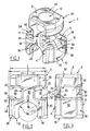
- connector 2 according to the present embodiment of the invention a a general shape of a rectangular parallelepiped presenting the cutouts which will be detailed more far and, at its edges, rounded avoiding any risk of injury to the arthrodesic body.
- the connector has two vertical flat faces front and rear 4 substantially parallel to each other and extending in continuity over the entire height of the connector. It also has two flat faces upper and lower horizontal 8, 10 parallel between them and substantially perpendicular to the faces vertical 4 above.
- the connector has a generally cylindrical conduit 12 extending parallel to the front and rear faces 4, halfway of these, and perpendicular to the faces upper and lower 8, 10 in which it opens.
- Connector has axial symmetry along the axis of conduit 12.
- the connector has two notches 14 generally extending parallel to the faces upper and lower 8, 10 from two sides side 20 of the connector perpendicular to the faces front and rear 4.
- Each notch 14 has a profile general in "U” and is delimited by a face upper 22 parallel to the upper face 8 of the connector, a bottom face 24 parallel to the faces side 20 of the connector, and a lower face 26 extending opposite the upper face 22 while being perpendicular to the front and rear faces 4, and slightly tilted towards the inside of the connector.
- the angle between the upper 22 and lower 26 faces of the notch will for example be between 2 ° and 10 °.
- the notches 14 delimit with the conduit 12 extending between them, a housing 28 for reception of a cross as we will see.
- the notches 14 delimit two junctions 30 between which the conduit 12 and the housing 28.
- a part of the connector extending above the junctions 30 form a head 32.
- the two side faces 20 are formed as two sectors of a same cylinder coaxial with conduit 12.
- the connector has a cylindrical face lower 34 contiguous to the lower face 10 of the connector, perpendicular to conduit 12 and halfway of the two side faces 20.
- the notches 14 and this cylindrical face 34 delimit two jaws 36 connected to the head 32 each by the two junctions 30.
- the connector On each junction 30, the connector has a slot 38 extending in the opposite direction to the jaws 36, towards the head 32.
- the conduit 12 has a smaller diameter at level of the head 32 as in the rest of the connector. In the head 32, this conduit 12 has a net 40.
- Width means the dimension measured perpendicular to side faces 20 of the connector, the width j of the junctions 30 is less than the width t of the head 32 and to the width c of the connector at the level of the jaws 36.
- the device comprises at least two connectors 2 such as that of FIG. 1. It comprises two screws 42 adapted to form a screw-nut connection by engaging in the conduit 12 of the head 32 of the connectors respectively. Each screw 42 has an imprint hexagonal 44 for receiving a hexagon wrench in order to operate the screw 42 received in the conduit 12.
- the device includes two longitudinal rods straight 48 intended to extend along the spine of a patient being each fixed to the vertebrae by anchoring members not shown and known in themselves.
- the two rods 48 have a circular profile of same diameter as the cylindrical face 34 of the jaws.
- the jaws 36 are suitable for making surface contact against surface with this rod.
- the cylindrical face 34 jaws extend in total on an upper arc 180 ° and chosen according to the material properties of the connector so that the jaws can be engaged 36 on the rod 48 by clipping them thereon.
- the face cylindrical 34 of the jaws has a geometric outline shown in dashes in Figure 2 which extends beyond of the underside 10 of the connector 2.
- the device finally comprises a cross straight 50 with generally rectangular section adapted to extend into the housings 28 through connectors 2 right through.
- All elements of the device are made of steel preferably biocompatible stainless steel.
- the assembly of the device is carried out as follows.
- the screw 42 biases the cross-member 50 down towards the jaws 36 along the axis of the conduit 12 on a flat upper face 54 of this rod.
- This stress is represented by the arrow V.
- This stress V causes the rod 52 biases the two jaws 36 at their edges 54 in the same direction and in the same direction.
- the corresponding requests are represented by arrows T.
- the jaws 36 Due to the configuration of junctions 30, slots 38 and the elasticity of the material, the jaws 36 are movable in rotation relative to the head 32 around an axis 58 parallel to the longitudinal rod 48 and passing through the slots 38.
- This mobility is represented by the arrows R. Therefore, the stresses T, distances from axis 58 and perpendicular to it, move the jaws 36 in rotation towards each other to tighten the longitudinal rod 48.
- Slot 28 is configured so that it allows angular travel a of the crossmember 50 around the axis of conduit 12, on either side of the direction perpendicular to the rod 48, as shown Figure 7. We can thus fix the cross 50 in a position not exactly perpendicular to the rod 48.
- the travel a will be for example plus or minus 15 ° on either side of the perpendicular direction, that is 30 ° in total.
- the osteosynthesis device will include advantageously several pairs of connectors 2 having each a cross 50, associated with these same two rods longitudinal 48 along the spine.
- the jaws 36 may be adapted to by the elasticity of the connector material to tighten the rod 48 in the absence of any solicitation by the crosspiece and screw 42. For this, it suffices to form the bit in a naturally closer position one of the other than when they receive the rod 48. Nevertheless, the jaws will allow manual movement of the connector along the rod for its repositioning.
- the connector 2 is adapted to slide on rod 48.
Landscapes
- Health & Medical Sciences (AREA)
- Orthopedic Medicine & Surgery (AREA)
- Life Sciences & Earth Sciences (AREA)
- Neurology (AREA)
- Surgery (AREA)
- Heart & Thoracic Surgery (AREA)
- Engineering & Computer Science (AREA)
- Biomedical Technology (AREA)
- Nuclear Medicine, Radiotherapy & Molecular Imaging (AREA)
- Medical Informatics (AREA)
- Molecular Biology (AREA)
- Animal Behavior & Ethology (AREA)
- General Health & Medical Sciences (AREA)
- Public Health (AREA)
- Veterinary Medicine (AREA)
- Surgical Instruments (AREA)
- Orthopedics, Nursing, And Contraception (AREA)
- Prostheses (AREA)
Claims (15)
- Verbindungsstück (2) für eine Osteosynthesevorrichtung des Rückgrates, mit zwei Spannbacken (36), und eine Aufnahme (28), die dafür eingerichtet ist, eine Stange (50) aufzunehmen, welche sich auf die Spannbacken (36) auflegt, wobei das Verbindungsstück (2) derart eingerichtet ist, dass eine Beanspruchung der in der Aufnahme aufgenommenen Stange (50) in Richtung der Spannbacken (36) die Spannbacken in Richtung zueinander hin spannt, dadurch gekennzeichnet, dass das Verbindungsstück (2) aus einem einzigen Stück gebildet ist.
- Verbindungsstück gemäß Anspruch 1, dadurch gekennzeichnet, dass es wenigstens eine an die Spannbacken (36) angrenzende Verbindungsstelle (30) aufweist, wobei die Verbindungsstelle eine kleinere Breite (j) als eine Breite (c) des Verbindungsstückes auf der Höhe der Spannbacken aufweist.
- Verbindungsstück gemäß Anspruch 2, dadurch gekennzeichnet, dass die Verbindungsstelle (30) eine Spalte (38) aufweist, die sich ausgehend von den Spannbacken (36) in deren entgegen gesetzte Richtung erstreckt.
- Verbindungsstück gemäß Anspruch 2 oder 3, dadurch gekennzeichnet, dass es einen Kopf (32) aufweist, der durch die Verbindungsstelle (30) mit den Spannbacken (36) verbunden ist, wobei die Breite (j) der Verbindungsstelle kleiner als eine Breite (t) des Kopfes ist.
- Verbindungsstück gemäß irgendeinem der Ansprüche 2 bis 4, dadurch gekennzeichnet, dass es derart angeordnet ist, dass die in der Aufnahme (28) aufgenommene Stange (50) auf einem von der Verbindungsstelle (30) entfernt liegenden Bereich (54) der Spannbacken (36) aufliegt.
- Verbindungsstück gemäß Anspruch 5, dadurch gekennzeichnet, dass es derart angeordnet ist, dass die in der Aufnahme (28) aufgenommene Stange (50) auf einer von der Verbindungsstelle (30) entfernt liegenden Kante (54) der Spannbacken (36) aufliegt.
- Verbindungsstück gemäß Anspruch 6, dadurch gekennzeichnet, dass die Spannbacken (36) jeweils eine ebene Fläche (26) aufweisen, die dafür eingerichtet ist, sich gegenüber der in der Aufnahme (28) aufgenommenen Stange (50) zu erstrecken, wobei diese Fläche zu dem inneren Bereich des Verbindungsstückes hin geneigt ist.
- Verbindungsstück gemäß irgendeinem der Ansprüche 1 bis 7, dadurch gekennzeichnet, dass es eine gewindete Fläche (12) aufweist, wobei sich die Aufnahme (28) zwischen den Spannbacken (36) und der gewindeten Fläche erstreckt.
- Verbindungsstück gemäß Anspruch 8, dadurch gekennzeichnet, dass die gewindete Fläche (12) von einem sich in das Verbindungsstück erstreckenden Kanal gebildet ist.
- Osteosynthesevorrichtung mit einer ersten und zweiten Stange (48, 50), einem gewindeten Organ (42) und einem Verbindungsstück (2) gemäß irgendeinem der vorherigen Ansprüche, dessen zwei Spannbacken (36) dafür eingerichtet sind, die erste Stange (48) einzuspannen, wobei das Verbindungsstück eine gewindete Fläche (12) aufweist und wobei die Aufnahme (28), sich zwischen den Spannbacken (36) und der gewindeten Fläche (12) erstreckt, und welche dafür eingerichtet ist, die zweite Stange (50) aufzunehmen, welche sich auf die Spannbacken auflegt, wobei das Verbindungsstück derart angeordnet ist, dass eine Beanspruchung (T) der zweiten, in der Aufnahme (28) aufgenommenen Stange (50) in Richtung der Spannbacken (36) durch das gewindete Organ (42), das mit der gewindeten Fläche (12) zusammenwirkt, die Spannbacken in Richtung zueinander hin spannt, um die erste Stange (48) einzuspannen.
- Vorrichtung gemäß Anspruch 10, dadurch gekennzeichnet, dass die Spannbacken (36) dafür eingerichtet sind, auf der ersten Stange (48) festgeklemmt zu werden.
- Vorrichtung gemäß Anspruch 11, dadurch gekennzeichnet, dass die Spannbacken (36) dafür eingerichtet sind, die erste Stange (48) bei Fehlen einer Spannung auf den Spannbacken einzuspannen.
- Vorrichtung gemäß irgendeinem der Ansprüche 10 bis 12, dadurch gekennzeichnet, dass die Spannbacken (36) derart gestaltet sind, dass die erste Stange (48) von den Spannbacken gemäß einer radialen Richtung zu der ersten Stange vorspringt, wenn die erste Stange zwischen den Spannbacken aufgenommen ist.
- Vorrichtung gemäß irgendeinem der Ansprüche 10 bis 13, dadurch gekennzeichnet, dass das Verbindungsstück (2) derart angeordnet ist, dass die zweite Stange (50) in der Aufnahme (28) aufgenommen werden kann, wobei sie eine bezüglich einer senkrecht zu der ersten Stange (48) liegenden Richtung variable Winkelposition einnimmt.
- Vorrichtung gemäß irgendeinem der Ansprüche 10 bis 14, dadurch gekennzeichnet, dass die erste Stange (48) eine intervertebrale Verbindung entlang des Rückgrates bildet, und die zweite Stange (50) eine Querverbindung zwischen der ersten Stange (48) und einer anderen, eine intervertebrale Verbindung bildenden Stange (48) bildet.
Applications Claiming Priority (3)
| Application Number | Priority Date | Filing Date | Title |
|---|---|---|---|
| FR9715540 | 1997-12-09 | ||
| FR9715540A FR2771918B1 (fr) | 1997-12-09 | 1997-12-09 | Connecteur pour dispositif d'osteosynthese rachidienne |
| PCT/FR1998/002651 WO1999029248A1 (fr) | 1997-12-09 | 1998-12-08 | Connecteur pour dispositif d'osteosynthese rachidienne |
Publications (2)
| Publication Number | Publication Date |
|---|---|
| EP1037564A1 EP1037564A1 (de) | 2000-09-27 |
| EP1037564B1 true EP1037564B1 (de) | 2003-04-09 |
Family
ID=9514346
Family Applications (1)
| Application Number | Title | Priority Date | Filing Date |
|---|---|---|---|
| EP98958974A Expired - Lifetime EP1037564B1 (de) | 1997-12-09 | 1998-12-08 | Verbinder für vorrichtung zur osteosynthese der wirbelsäule |
Country Status (11)
| Country | Link |
|---|---|
| US (1) | US6368320B1 (de) |
| EP (1) | EP1037564B1 (de) |
| JP (1) | JP2001525213A (de) |
| KR (1) | KR20010032962A (de) |
| AT (1) | ATE236582T1 (de) |
| AU (1) | AU736307B2 (de) |
| CA (1) | CA2313531A1 (de) |
| DE (2) | DE69813290T2 (de) |
| ES (1) | ES2151470T3 (de) |
| FR (1) | FR2771918B1 (de) |
| WO (1) | WO1999029248A1 (de) |
Families Citing this family (98)
| Publication number | Priority date | Publication date | Assignee | Title |
|---|---|---|---|---|
| DE60032225T2 (de) * | 1999-03-30 | 2007-09-13 | Howmedica Osteonics Corp. | Apparat zur stabilisierung der wirbelsäule |
| FR2796545B1 (fr) * | 1999-07-22 | 2002-03-15 | Dimso Sa | Liaison poly-axiale pour systeme d'osteosynthese, notamment pour le rachis |
| US6811567B2 (en) * | 1999-10-22 | 2004-11-02 | Archus Orthopedics Inc. | Facet arthroplasty devices and methods |
| WO2001030248A1 (en) * | 1999-10-22 | 2001-05-03 | Reiley Mark A | Facet arthroplasty devices and methods |
| US7691145B2 (en) * | 1999-10-22 | 2010-04-06 | Facet Solutions, Inc. | Prostheses, systems and methods for replacement of natural facet joints with artificial facet joint surfaces |
| US7674293B2 (en) | 2004-04-22 | 2010-03-09 | Facet Solutions, Inc. | Crossbar spinal prosthesis having a modular design and related implantation methods |
| US8187303B2 (en) | 2004-04-22 | 2012-05-29 | Gmedelaware 2 Llc | Anti-rotation fixation element for spinal prostheses |
| US6974478B2 (en) * | 1999-10-22 | 2005-12-13 | Archus Orthopedics, Inc. | Prostheses, systems and methods for replacement of natural facet joints with artificial facet joint surfaces |
| JP2004516040A (ja) | 2000-06-30 | 2004-06-03 | リトラン、スティーブン | 多軸継手装置及び方法 |
| EP1591072B1 (de) * | 2001-04-24 | 2008-01-02 | coLigne AG | Instrumentarium zur Stabilisierung gewisser Wirbel der Wirbelsäule |
| AU2002327801B2 (en) | 2001-09-28 | 2008-03-06 | Stephen Ritland | Connection rod for screw or hook polyaxial system and method of use |
| US6991632B2 (en) | 2001-09-28 | 2006-01-31 | Stephen Ritland | Adjustable rod and connector device and method of use |
| FR2831048B1 (fr) | 2001-10-18 | 2004-09-17 | Ldr Medical | Dispositif d'osteosynthese a approche progressive et procede de premontage |
| FR2835734B1 (fr) * | 2002-02-11 | 2004-10-29 | Scient X | Systeme de liaison entre une tige rachidienne et une barre transversale |
| US7763047B2 (en) | 2002-02-20 | 2010-07-27 | Stephen Ritland | Pedicle screw connector apparatus and method |
| US6966910B2 (en) | 2002-04-05 | 2005-11-22 | Stephen Ritland | Dynamic fixation device and method of use |
| EP2457528A1 (de) | 2002-05-08 | 2012-05-30 | Stephen Ritland | Dynamische Befestigungsvorrichtung und Verwendungsverfahren dafür |
| US20040015166A1 (en) * | 2002-07-22 | 2004-01-22 | Gorek Josef E. | System and method for stabilizing the spine by securing spine stabilization rods in crossed disposition |
| FR2845269B1 (fr) * | 2002-10-07 | 2005-06-24 | Spine Next Sa | Systeme de fixation a plaque |
| US20040230304A1 (en) | 2003-05-14 | 2004-11-18 | Archus Orthopedics Inc. | Prostheses, tools and methods for replacement of natural facet joints with artifical facet joint surfaces |
| US7608104B2 (en) | 2003-05-14 | 2009-10-27 | Archus Orthopedics, Inc. | Prostheses, tools and methods for replacement of natural facet joints with artifical facet joint surfaces |
| DE10326643A1 (de) * | 2003-06-11 | 2004-12-30 | Mückter, Helmut, Dr. med. Dipl.-Ing. | Osteosyntheseplatte oder vergleichbares Implantat nebst Kugelhülse |
| US7074238B2 (en) | 2003-07-08 | 2006-07-11 | Archus Orthopedics, Inc. | Prostheses, tools and methods for replacement of natural facet joints with artificial facet joint surfaces |
| US20050131406A1 (en) | 2003-12-15 | 2005-06-16 | Archus Orthopedics, Inc. | Polyaxial adjustment of facet joint prostheses |
| US7635366B2 (en) * | 2003-12-29 | 2009-12-22 | Abdou M Samy | Plating system for bone fixation and method of implantation |
| US8029548B2 (en) * | 2008-05-05 | 2011-10-04 | Warsaw Orthopedic, Inc. | Flexible spinal stabilization element and system |
| US7914556B2 (en) | 2005-03-02 | 2011-03-29 | Gmedelaware 2 Llc | Arthroplasty revision system and method |
| WO2006055186A2 (en) | 2004-10-25 | 2006-05-26 | Archus Orthopedics, Inc. | Spinal prosthesis having a modular design |
| US7406775B2 (en) | 2004-04-22 | 2008-08-05 | Archus Orthopedics, Inc. | Implantable orthopedic device component selection instrument and methods |
| US7051451B2 (en) * | 2004-04-22 | 2006-05-30 | Archus Orthopedics, Inc. | Facet joint prosthesis measurement and implant tools |
| US7494489B2 (en) * | 2004-05-07 | 2009-02-24 | Jeffrey S. Roh | Systems and methods that facilitate minimally invasive spine surgery |
| US8764801B2 (en) * | 2005-03-28 | 2014-07-01 | Gmedelaware 2 Llc | Facet joint implant crosslinking apparatus and method |
| EP1758511A4 (de) * | 2004-06-14 | 2008-12-03 | M S Abdou | Occipitales fixationssystem und anwendungsverfahren |
| US7766945B2 (en) * | 2004-08-10 | 2010-08-03 | Lanx, Inc. | Screw and rod fixation system |
| WO2006023671A1 (en) | 2004-08-18 | 2006-03-02 | Archus Orthopedics, Inc. | Adjacent level facet arthroplasty devices, spine stabilization systems, and methods |
| US20060041311A1 (en) * | 2004-08-18 | 2006-02-23 | Mcleer Thomas J | Devices and methods for treating facet joints |
| US7959653B2 (en) * | 2004-09-03 | 2011-06-14 | Lanx, Inc. | Spinal rod cross connector |
| WO2006047555A2 (en) * | 2004-10-25 | 2006-05-04 | Alphaspine, Inc. | Bone fixation systems and methods |
| ATE524121T1 (de) | 2004-11-24 | 2011-09-15 | Abdou Samy | Vorrichtungen zur platzierung eines orthopädischen intervertebralen implantats |
| US7862588B2 (en) | 2005-02-18 | 2011-01-04 | Samy Abdou | Devices and methods for dynamic fixation of skeletal structure |
| WO2006096756A2 (en) * | 2005-03-07 | 2006-09-14 | Abdou M Samy | Occipital fixation system |
| US8496686B2 (en) * | 2005-03-22 | 2013-07-30 | Gmedelaware 2 Llc | Minimally invasive spine restoration systems, devices, methods and kits |
| US9942511B2 (en) | 2005-10-31 | 2018-04-10 | Invention Science Fund I, Llc | Preservation/degradation of video/audio aspects of a data stream |
| US7585314B2 (en) * | 2005-04-29 | 2009-09-08 | Warsaw Orthopedic, Inc. | Device for interconnecting components in spinal instrumentation |
| JP4613867B2 (ja) * | 2005-05-26 | 2011-01-19 | ソニー株式会社 | コンテンツ処理装置及びコンテンツ処理方法、並びにコンピュータ・プログラム |
| WO2007012025A2 (en) | 2005-07-19 | 2007-01-25 | Stephen Ritland | Rod extension for extending fusion construct |
| US7628799B2 (en) | 2005-08-23 | 2009-12-08 | Aesculap Ag & Co. Kg | Rod to rod connector |
| US8226689B2 (en) * | 2005-09-23 | 2012-07-24 | Zimmer Spine, Inc. | Apparatus and methods for spinal implant with variable link mechanism |
| EP1948050A1 (de) * | 2005-11-17 | 2008-07-30 | Chin, Kingsley R. | System und verfahren zur implantation von vorrichtungen zur wirbelsäulenstabilisierung |
| US20070191844A1 (en) * | 2006-01-31 | 2007-08-16 | Sdgi Holdings, Inc. | In-series, dual locking mechanism device |
| US7708736B2 (en) * | 2006-02-22 | 2010-05-04 | Extraortho, Inc. | Articulation apparatus for external fixation device |
| WO2008019397A2 (en) | 2006-08-11 | 2008-02-14 | Archus Orthopedics, Inc. | Angled washer polyaxial connection for dynamic spine prosthesis |
| US8876874B2 (en) * | 2006-08-21 | 2014-11-04 | M. Samy Abdou | Bone screw systems and methods of use |
| US7922746B2 (en) * | 2006-08-31 | 2011-04-12 | Warsaw Orthopedic, Inc. | Spinal rod extenders and methods of use |
| US20080177327A1 (en) * | 2006-10-17 | 2008-07-24 | Hugues Malandain | Central rod connector and T-rod |
| US8109975B2 (en) * | 2007-01-30 | 2012-02-07 | Warsaw Orthopedic, Inc. | Collar bore configuration for dynamic spinal stabilization assembly |
| US8029547B2 (en) * | 2007-01-30 | 2011-10-04 | Warsaw Orthopedic, Inc. | Dynamic spinal stabilization assembly with sliding collars |
| US20080281362A1 (en) * | 2007-05-09 | 2008-11-13 | Jeremy Lemoine | Device and system for cranial support |
| FR2916956B1 (fr) | 2007-06-08 | 2012-12-14 | Ldr Medical | Cage intersomatique,prothese intervertebrale,dispositif d'ancrage et instrumentation d'implantation |
| FR2918555B1 (fr) | 2007-07-12 | 2010-04-02 | Ldr Medical | Dispositif et systeme de liaison rachidienne transverse |
| US20090264933A1 (en) * | 2008-04-22 | 2009-10-22 | Warsaw Orthopedic, Inc. | Anchors for securing a rod to a vertebral member |
| US8414584B2 (en) | 2008-07-09 | 2013-04-09 | Icon Orthopaedic Concepts, Llc | Ankle arthrodesis nail and outrigger assembly |
| US8328807B2 (en) | 2008-07-09 | 2012-12-11 | Icon Orthopaedic Concepts, Llc | Ankle arthrodesis nail and outrigger assembly |
| WO2010017471A1 (en) * | 2008-08-07 | 2010-02-11 | The Children's Mercy Hospital | Sliding rod system for correcting spinal deformities |
| ES2387512T3 (es) * | 2008-09-05 | 2012-09-25 | Biedermann Technologies Gmbh & Co. Kg | Dispositivo de estabilización para huesos, en particular para la columna vertebral |
| EP3117788B1 (de) | 2008-11-03 | 2020-04-01 | Synthes GmbH | Uniplanare knochenfixationsanordnung |
| US8460342B2 (en) | 2008-12-03 | 2013-06-11 | Eminent Spine Llc | Spinal cross-connector and method for use of same |
| US8998961B1 (en) | 2009-02-26 | 2015-04-07 | Lanx, Inc. | Spinal rod connector and methods |
| KR20120013312A (ko) * | 2009-04-15 | 2012-02-14 | 신세스 게엠바하 | 척추 구조물용 교정 커넥터 |
| BRPI1012921A2 (pt) | 2009-06-17 | 2016-04-05 | Synthes Gmbh | conector de revisão para construção espinhal |
| US8568456B2 (en) | 2009-09-21 | 2013-10-29 | Globus Medical, Inc. | Transverse connector having a locking element for capturing multiple rods |
| US8764806B2 (en) | 2009-12-07 | 2014-07-01 | Samy Abdou | Devices and methods for minimally invasive spinal stabilization and instrumentation |
| US20110152937A1 (en) * | 2009-12-22 | 2011-06-23 | Warsaw Orthopedic, Inc. | Surgical Implants for Selectively Controlling Spinal Motion Segments |
| US20120283778A1 (en) * | 2010-03-31 | 2012-11-08 | Chung-Chun Yeh | Device for connecting transverse beam at triangular position of vertebral lamina |
| US8777996B2 (en) | 2010-07-12 | 2014-07-15 | Globus Medical, Inc. | Interspinous ligament transverse connector |
| US8845728B1 (en) | 2011-09-23 | 2014-09-30 | Samy Abdou | Spinal fixation devices and methods of use |
| JP2014533136A (ja) | 2011-10-05 | 2014-12-11 | マーク・エイ・ドッドソン | モジュール開創器および関連する方法 |
| US8758411B1 (en) | 2011-10-25 | 2014-06-24 | Nuvasive, Inc. | Implants and methods for treating spinal disorders |
| US8337532B1 (en) | 2011-12-08 | 2012-12-25 | Spine Wave, Inc. | Methods for percutaneously extending an existing spinal construct |
| US20130226240A1 (en) | 2012-02-22 | 2013-08-29 | Samy Abdou | Spinous process fixation devices and methods of use |
| US8992575B1 (en) * | 2012-06-22 | 2015-03-31 | Seaspine, Inc. | Spinal implants having offsets and hooks |
| US9198767B2 (en) | 2012-08-28 | 2015-12-01 | Samy Abdou | Devices and methods for spinal stabilization and instrumentation |
| US9320617B2 (en) | 2012-10-22 | 2016-04-26 | Cogent Spine, LLC | Devices and methods for spinal stabilization and instrumentation |
| US9827020B2 (en) * | 2013-03-14 | 2017-11-28 | Stryker European Holdings I, Llc | Percutaneous spinal cross link system and method |
| US20140277163A1 (en) * | 2013-03-15 | 2014-09-18 | Ryan Kretzer | Reinforcement systems for spine stabilization constructs |
| WO2015161071A1 (en) * | 2014-04-16 | 2015-10-22 | Buttermann Glenn R | Adjustable screw-clamp orthopedic apparatus |
| US10857003B1 (en) | 2015-10-14 | 2020-12-08 | Samy Abdou | Devices and methods for vertebral stabilization |
| US10398454B2 (en) * | 2015-11-09 | 2019-09-03 | Globus Medical, Inc. | MIS cross-connector |
| US10335205B2 (en) * | 2015-11-09 | 2019-07-02 | Globus Medical, Inc. | MIS cross-connector |
| ITUB20155792A1 (it) * | 2015-11-20 | 2017-05-20 | Medacta Int Sa | Placca occipitale per fissaggio occipito-cervicale e sistema per il fissaggio occipito-cervicale |
| ITUB20156292A1 (it) * | 2015-12-03 | 2017-06-03 | Medacta Int Sa | Elemento di connessione tra barre in un sistema di ricostruzione spinosa |
| US10744000B1 (en) | 2016-10-25 | 2020-08-18 | Samy Abdou | Devices and methods for vertebral bone realignment |
| US10973648B1 (en) | 2016-10-25 | 2021-04-13 | Samy Abdou | Devices and methods for vertebral bone realignment |
| US11103226B2 (en) * | 2017-12-19 | 2021-08-31 | Thompson Surgical Instruments, Inc. | Retractor system with tethered surgical retractor |
| US11179248B2 (en) | 2018-10-02 | 2021-11-23 | Samy Abdou | Devices and methods for spinal implantation |
| DE102019005376A1 (de) * | 2019-07-30 | 2021-02-04 | Signus Medizintechnik Gmbh | Verbindungseinrichtung für wirbelsäulenstütze |
| DE102020003247A1 (de) | 2020-05-29 | 2021-12-02 | Mimeo Medical Gmbh | Modulare Osteosynthesevorrichtung für Wirbel |
| US20240299065A1 (en) * | 2023-03-08 | 2024-09-12 | Nuvasive, Inc. | Percutaneous posterior fixation |
Family Cites Families (8)
| Publication number | Priority date | Publication date | Assignee | Title |
|---|---|---|---|---|
| US5527314A (en) * | 1993-01-04 | 1996-06-18 | Danek Medical, Inc. | Spinal fixation system |
| US5645544A (en) * | 1995-09-13 | 1997-07-08 | Danek Medical, Inc. | Variable angle extension rod |
| FR2742040B1 (fr) * | 1995-12-07 | 1998-01-23 | Groupe Lepine | Dispositif d'assemblage pour pieces allongees de materiel d'osteosynthese, notamment rachidienne |
| ES2145521T3 (es) * | 1996-01-24 | 2000-07-01 | Werner Hermann | Implante para la fijacion interna de vertebras y herramienta para cortar tornillos pediculares. |
| FR2750033B1 (fr) * | 1996-06-20 | 1998-09-11 | Euros Sa | Dispositif de liaison transversale de tiges d'implants rachidiens |
| ATE191327T1 (de) * | 1997-01-23 | 2000-04-15 | Werner Hermann | Klemmanordnungen für orthopädischen fixateur und verwendungen derselben |
| US6173311B1 (en) * | 1997-02-13 | 2001-01-09 | Pointcast, Inc. | Apparatus, method and article of manufacture for servicing client requests on a network |
| US5810819A (en) * | 1997-05-15 | 1998-09-22 | Spinal Concepts, Inc. | Polyaxial pedicle screw having a compression locking rod gripping mechanism |
-
1997
- 1997-12-09 FR FR9715540A patent/FR2771918B1/fr not_active Expired - Fee Related
-
1998
- 1998-12-08 AU AU14924/99A patent/AU736307B2/en not_active Ceased
- 1998-12-08 KR KR1020007006309A patent/KR20010032962A/ko not_active Withdrawn
- 1998-12-08 JP JP2000523927A patent/JP2001525213A/ja active Pending
- 1998-12-08 ES ES98958974T patent/ES2151470T3/es not_active Expired - Lifetime
- 1998-12-08 US US09/581,104 patent/US6368320B1/en not_active Expired - Lifetime
- 1998-12-08 DE DE69813290T patent/DE69813290T2/de not_active Expired - Lifetime
- 1998-12-08 EP EP98958974A patent/EP1037564B1/de not_active Expired - Lifetime
- 1998-12-08 CA CA002313531A patent/CA2313531A1/fr not_active Abandoned
- 1998-12-08 DE DE1037564T patent/DE1037564T1/de active Pending
- 1998-12-08 WO PCT/FR1998/002651 patent/WO1999029248A1/fr not_active Ceased
- 1998-12-08 AT AT98958974T patent/ATE236582T1/de not_active IP Right Cessation
Also Published As
| Publication number | Publication date |
|---|---|
| ATE236582T1 (de) | 2003-04-15 |
| CA2313531A1 (fr) | 1999-06-17 |
| ES2151470T3 (es) | 2003-09-01 |
| DE1037564T1 (de) | 2001-05-03 |
| WO1999029248A1 (fr) | 1999-06-17 |
| FR2771918B1 (fr) | 2000-04-21 |
| AU736307B2 (en) | 2001-07-26 |
| EP1037564A1 (de) | 2000-09-27 |
| AU1492499A (en) | 1999-06-28 |
| JP2001525213A (ja) | 2001-12-11 |
| DE69813290D1 (de) | 2003-05-15 |
| FR2771918A1 (fr) | 1999-06-11 |
| KR20010032962A (ko) | 2001-04-25 |
| DE69813290T2 (de) | 2004-01-22 |
| US6368320B1 (en) | 2002-04-09 |
| ES2151470T1 (es) | 2001-01-01 |
Similar Documents
| Publication | Publication Date | Title |
|---|---|---|
| EP1037564B1 (de) | Verbinder für vorrichtung zur osteosynthese der wirbelsäule | |
| EP1017328B1 (de) | Platte- und schraubensystem zur osteosynthese der wirbelsäule | |
| EP1011504B1 (de) | Vorrichtung zur osteosynthese die ein verbindungselement der wirbelsaülenstange und der verankerungselemente aufweist | |
| EP1480569B1 (de) | Verbindungssystem zwischen einer wirbelsäulenstange und einem querträger | |
| EP1578289B1 (de) | Vorrichtung mit vorderplatte für wirbelsäulenabstützung | |
| EP1415602B1 (de) | Modulare, platzsparende und multidirektionelle Osteosynthesevorrichtung für die Wirbelsäule | |
| EP1339337B1 (de) | Vorrichtung zur befestigung einer stange und eines kugelsymmetrischen schraubenkopfs | |
| FR2681776A1 (fr) | Dispositif d'osteosynthese vertebrale. | |
| WO1999044527A1 (fr) | Systeme pour l'osteosynthese du rachis avec ligament | |
| EP1429672B1 (de) | Vorrichtung zur wirbelsäulenfixierung | |
| WO1998029046A1 (fr) | Systeme d'osteosynthese du rachis avec reglage en position | |
| WO1998049960A1 (fr) | Systeme d'osteosynthese pour arthrodese vertebrale | |
| EP0778007A1 (de) | Verbindungsvorrichtung für langgestreckte Osteosyntheseteile, insbesondere für die Wirbelsäule | |
| EP1119305A1 (de) | Spinales osteosynthesesystem mit verbesserter stabilität | |
| FR2836368A1 (fr) | Dispositif de liaison sequentiel | |
| FR2835174A1 (fr) | Connecteur pour dispositif d'osteosynthese rachidienne, ensemble connecteur/organe d'ancrage osseux et dispositif d'osteosynthese rachidienne utilisant cet ensemble | |
| CA2330705A1 (fr) | Systeme d'osteosynthese rachidienne pour une fixation anterieure | |
| FR2697743A1 (fr) | Dispositif d'ostéosynthèse rachidienne applicable notamment aux vertèbres dégénératives. | |
| FR2861981A1 (fr) | Materiel d'osteosynthese vertebrale | |
| FR2776111A1 (fr) | Appui d'epaule reglable pour violons ou instruments analogues | |
| FR3035584A1 (fr) | Materiel d'osteosynthese vertebrale | |
| EP3327325B1 (de) | Vorrichtung zur befestigung mindestens eines kabels an einer leitung, und verfahren zur umsetzung einer solchen vorrichtung | |
| WO1999044526A1 (fr) | Organe d'osteosynthese rachidien pour la fixation d'un ligament | |
| EP0269538A1 (de) | Richtarm und Einrichtung zum Richten von verformten Karosserien oder anderen Fahrzeugteilen | |
| WO1999053855A1 (fr) | Dispositif d'osteosynthese rachidienne avec cadre et fils |
Legal Events
| Date | Code | Title | Description |
|---|---|---|---|
| PUAI | Public reference made under article 153(3) epc to a published international application that has entered the european phase |
Free format text: ORIGINAL CODE: 0009012 |
|
| 17P | Request for examination filed |
Effective date: 20000626 |
|
| AK | Designated contracting states |
Kind code of ref document: A1 Designated state(s): AT BE CH CY DE DK ES FI FR GB GR IE IT LI LU MC NL PT SE |
|
| GBC | Gb: translation of claims filed (gb section 78(7)/1977) | ||
| REG | Reference to a national code |
Ref country code: ES Ref legal event code: BA2A Ref document number: 2151470 Country of ref document: ES Kind code of ref document: T1 |
|
| DET | De: translation of patent claims | ||
| GRAG | Despatch of communication of intention to grant |
Free format text: ORIGINAL CODE: EPIDOS AGRA |
|
| 17Q | First examination report despatched |
Effective date: 20020425 |
|
| GRAG | Despatch of communication of intention to grant |
Free format text: ORIGINAL CODE: EPIDOS AGRA |
|
| GRAG | Despatch of communication of intention to grant |
Free format text: ORIGINAL CODE: EPIDOS AGRA |
|
| GRAH | Despatch of communication of intention to grant a patent |
Free format text: ORIGINAL CODE: EPIDOS IGRA |
|
| GRAH | Despatch of communication of intention to grant a patent |
Free format text: ORIGINAL CODE: EPIDOS IGRA |
|
| GRAA | (expected) grant |
Free format text: ORIGINAL CODE: 0009210 |
|
| AK | Designated contracting states |
Designated state(s): AT BE CH CY DE DK ES FI FR GB GR IE IT LI LU MC NL PT SE |
|
| PG25 | Lapsed in a contracting state [announced via postgrant information from national office to epo] |
Ref country code: NL Free format text: LAPSE BECAUSE OF FAILURE TO SUBMIT A TRANSLATION OF THE DESCRIPTION OR TO PAY THE FEE WITHIN THE PRESCRIBED TIME-LIMIT Effective date: 20030409 Ref country code: IE Free format text: LAPSE BECAUSE OF FAILURE TO SUBMIT A TRANSLATION OF THE DESCRIPTION OR TO PAY THE FEE WITHIN THE PRESCRIBED TIME-LIMIT Effective date: 20030409 Ref country code: FI Free format text: LAPSE BECAUSE OF FAILURE TO SUBMIT A TRANSLATION OF THE DESCRIPTION OR TO PAY THE FEE WITHIN THE PRESCRIBED TIME-LIMIT Effective date: 20030409 Ref country code: AT Free format text: LAPSE BECAUSE OF FAILURE TO SUBMIT A TRANSLATION OF THE DESCRIPTION OR TO PAY THE FEE WITHIN THE PRESCRIBED TIME-LIMIT Effective date: 20030409 |
|
| REG | Reference to a national code |
Ref country code: GB Ref legal event code: FG4D Free format text: NOT ENGLISH |
|
| REG | Reference to a national code |
Ref country code: CH Ref legal event code: EP |
|
| GBT | Gb: translation of ep patent filed (gb section 77(6)(a)/1977) |
Effective date: 20030409 |
|
| REG | Reference to a national code |
Ref country code: IE Ref legal event code: FG4D Free format text: FRENCH |
|
| REG | Reference to a national code |
Ref country code: CH Ref legal event code: NV Representative=s name: MICHELI & CIE INGENIEURS-CONSEILS |
|
| PG25 | Lapsed in a contracting state [announced via postgrant information from national office to epo] |
Ref country code: SE Free format text: LAPSE BECAUSE OF FAILURE TO SUBMIT A TRANSLATION OF THE DESCRIPTION OR TO PAY THE FEE WITHIN THE PRESCRIBED TIME-LIMIT Effective date: 20030709 Ref country code: PT Free format text: LAPSE BECAUSE OF FAILURE TO SUBMIT A TRANSLATION OF THE DESCRIPTION OR TO PAY THE FEE WITHIN THE PRESCRIBED TIME-LIMIT Effective date: 20030709 Ref country code: GR Free format text: LAPSE BECAUSE OF FAILURE TO SUBMIT A TRANSLATION OF THE DESCRIPTION OR TO PAY THE FEE WITHIN THE PRESCRIBED TIME-LIMIT Effective date: 20030709 Ref country code: DK Free format text: LAPSE BECAUSE OF FAILURE TO SUBMIT A TRANSLATION OF THE DESCRIPTION OR TO PAY THE FEE WITHIN THE PRESCRIBED TIME-LIMIT Effective date: 20030709 |
|
| NLV1 | Nl: lapsed or annulled due to failure to fulfill the requirements of art. 29p and 29m of the patents act | ||
| REG | Reference to a national code |
Ref country code: ES Ref legal event code: FG2A Ref document number: 2151470 Country of ref document: ES Kind code of ref document: T3 |
|
| REG | Reference to a national code |
Ref country code: IE Ref legal event code: FD4D Ref document number: 1037564E Country of ref document: IE |
|
| PG25 | Lapsed in a contracting state [announced via postgrant information from national office to epo] |
Ref country code: LU Free format text: LAPSE BECAUSE OF NON-PAYMENT OF DUE FEES Effective date: 20031208 Ref country code: CY Free format text: LAPSE BECAUSE OF FAILURE TO SUBMIT A TRANSLATION OF THE DESCRIPTION OR TO PAY THE FEE WITHIN THE PRESCRIBED TIME-LIMIT Effective date: 20031208 |
|
| PG25 | Lapsed in a contracting state [announced via postgrant information from national office to epo] |
Ref country code: MC Free format text: LAPSE BECAUSE OF NON-PAYMENT OF DUE FEES Effective date: 20031231 Ref country code: BE Free format text: LAPSE BECAUSE OF NON-PAYMENT OF DUE FEES Effective date: 20031231 |
|
| PLBE | No opposition filed within time limit |
Free format text: ORIGINAL CODE: 0009261 |
|
| STAA | Information on the status of an ep patent application or granted ep patent |
Free format text: STATUS: NO OPPOSITION FILED WITHIN TIME LIMIT |
|
| 26N | No opposition filed |
Effective date: 20040112 |
|
| BERE | Be: lapsed |
Owner name: DISTRIBUTION MEDICALE DU SUD OUEST *DIMSO Effective date: 20031231 |
|
| REG | Reference to a national code |
Ref country code: CH Ref legal event code: PFA Owner name: STRYKER SPINE Free format text: DIMSO DISTRIBUTION MEDICALE DU SUD OUEST#ZI DE MARTICOT#33610 CESTAS (FR) -TRANSFER TO- STRYKER SPINE#ZI DE MARTICOT#33610 CESTAS (FR) Ref country code: CH Ref legal event code: NV Representative=s name: ISLER & PEDRAZZINI AG |
|
| REG | Reference to a national code |
Ref country code: FR Ref legal event code: CD |
|
| PGFP | Annual fee paid to national office [announced via postgrant information from national office to epo] |
Ref country code: CH Payment date: 20061026 Year of fee payment: 9 |
|
| PGFP | Annual fee paid to national office [announced via postgrant information from national office to epo] |
Ref country code: ES Payment date: 20061220 Year of fee payment: 9 |
|
| PGFP | Annual fee paid to national office [announced via postgrant information from national office to epo] |
Ref country code: IT Payment date: 20061231 Year of fee payment: 9 |
|
| REG | Reference to a national code |
Ref country code: ES Ref legal event code: PC2A |
|
| REG | Reference to a national code |
Ref country code: HK Ref legal event code: WD Ref document number: 1030866 Country of ref document: HK |
|
| REG | Reference to a national code |
Ref country code: CH Ref legal event code: PCAR Free format text: ISLER & PEDRAZZINI AG;POSTFACH 1772;8027 ZUERICH (CH) |
|
| REG | Reference to a national code |
Ref country code: CH Ref legal event code: PL |
|
| PG25 | Lapsed in a contracting state [announced via postgrant information from national office to epo] |
Ref country code: LI Free format text: LAPSE BECAUSE OF NON-PAYMENT OF DUE FEES Effective date: 20071231 Ref country code: CH Free format text: LAPSE BECAUSE OF NON-PAYMENT OF DUE FEES Effective date: 20071231 |
|
| REG | Reference to a national code |
Ref country code: ES Ref legal event code: FD2A Effective date: 20071210 |
|
| PG25 | Lapsed in a contracting state [announced via postgrant information from national office to epo] |
Ref country code: ES Free format text: LAPSE BECAUSE OF NON-PAYMENT OF DUE FEES Effective date: 20071210 |
|
| PG25 | Lapsed in a contracting state [announced via postgrant information from national office to epo] |
Ref country code: IT Free format text: LAPSE BECAUSE OF NON-PAYMENT OF DUE FEES Effective date: 20071208 |
|
| PGFP | Annual fee paid to national office [announced via postgrant information from national office to epo] |
Ref country code: GB Payment date: 20131126 Year of fee payment: 16 |
|
| PGFP | Annual fee paid to national office [announced via postgrant information from national office to epo] |
Ref country code: FR Payment date: 20131126 Year of fee payment: 16 |
|
| PGFP | Annual fee paid to national office [announced via postgrant information from national office to epo] |
Ref country code: DE Payment date: 20131230 Year of fee payment: 16 |
|
| REG | Reference to a national code |
Ref country code: DE Ref legal event code: R119 Ref document number: 69813290 Country of ref document: DE |
|
| GBPC | Gb: european patent ceased through non-payment of renewal fee |
Effective date: 20141208 |
|
| REG | Reference to a national code |
Ref country code: FR Ref legal event code: ST Effective date: 20150831 |
|
| PG25 | Lapsed in a contracting state [announced via postgrant information from national office to epo] |
Ref country code: DE Free format text: LAPSE BECAUSE OF NON-PAYMENT OF DUE FEES Effective date: 20150701 Ref country code: GB Free format text: LAPSE BECAUSE OF NON-PAYMENT OF DUE FEES Effective date: 20141208 |
|
| PG25 | Lapsed in a contracting state [announced via postgrant information from national office to epo] |
Ref country code: FR Free format text: LAPSE BECAUSE OF NON-PAYMENT OF DUE FEES Effective date: 20141231 |