EP1037568B1 - Recipient sterile pour applications medicales - Google Patents
Recipient sterile pour applications medicales Download PDFInfo
- Publication number
- EP1037568B1 EP1037568B1 EP98963559A EP98963559A EP1037568B1 EP 1037568 B1 EP1037568 B1 EP 1037568B1 EP 98963559 A EP98963559 A EP 98963559A EP 98963559 A EP98963559 A EP 98963559A EP 1037568 B1 EP1037568 B1 EP 1037568B1
- Authority
- EP
- European Patent Office
- Prior art keywords
- flap
- sterile container
- container according
- lid
- closure
- Prior art date
- Legal status (The legal status is an assumption and is not a legal conclusion. Google has not performed a legal analysis and makes no representation as to the accuracy of the status listed.)
- Expired - Lifetime
Links
Images

Classifications
-
- E—FIXED CONSTRUCTIONS
- E05—LOCKS; KEYS; WINDOW OR DOOR FITTINGS; SAFES
- E05C—BOLTS OR FASTENING DEVICES FOR WINGS, SPECIALLY FOR DOORS OR WINDOWS
- E05C5/00—Fastening devices with bolts moving otherwise than only rectilinearly and only pivotally or rotatively
-
- A—HUMAN NECESSITIES
- A61—MEDICAL OR VETERINARY SCIENCE; HYGIENE
- A61B—DIAGNOSIS; SURGERY; IDENTIFICATION
- A61B50/00—Containers, covers, furniture or holders specially adapted for surgical or diagnostic appliances or instruments, e.g. sterile covers
-
- A—HUMAN NECESSITIES
- A61—MEDICAL OR VETERINARY SCIENCE; HYGIENE
- A61L—METHODS OR APPARATUS FOR STERILISING MATERIALS OR OBJECTS IN GENERAL; DISINFECTION, STERILISATION OR DEODORISATION OF AIR; CHEMICAL ASPECTS OF BANDAGES, DRESSINGS, ABSORBENT PADS OR SURGICAL ARTICLES; MATERIALS FOR BANDAGES, DRESSINGS, ABSORBENT PADS OR SURGICAL ARTICLES
- A61L2/00—Disinfection or sterilisation of materials or objects, in general; Accessories therefor
- A61L2/26—Accessories
-
- A—HUMAN NECESSITIES
- A61—MEDICAL OR VETERINARY SCIENCE; HYGIENE
- A61B—DIAGNOSIS; SURGERY; IDENTIFICATION
- A61B50/00—Containers, covers, furniture or holders specially adapted for surgical or diagnostic appliances or instruments, e.g. sterile covers
- A61B2050/005—Containers, covers, furniture or holders specially adapted for surgical or diagnostic appliances or instruments, e.g. sterile covers with a lid or cover
- A61B2050/0067—Types of closures or fasteners
- A61B2050/0074—Toggle latches or clamps
-
- A—HUMAN NECESSITIES
- A61—MEDICAL OR VETERINARY SCIENCE; HYGIENE
- A61L—METHODS OR APPARATUS FOR STERILISING MATERIALS OR OBJECTS IN GENERAL; DISINFECTION, STERILISATION OR DEODORISATION OF AIR; CHEMICAL ASPECTS OF BANDAGES, DRESSINGS, ABSORBENT PADS OR SURGICAL ARTICLES; MATERIALS FOR BANDAGES, DRESSINGS, ABSORBENT PADS OR SURGICAL ARTICLES
- A61L2103/00—Materials or objects being the target of disinfection or sterilisation
- A61L2103/15—Laboratory, medical or dentistry appliances, e.g. catheters or sharps
-
- A—HUMAN NECESSITIES
- A61—MEDICAL OR VETERINARY SCIENCE; HYGIENE
- A61L—METHODS OR APPARATUS FOR STERILISING MATERIALS OR OBJECTS IN GENERAL; DISINFECTION, STERILISATION OR DEODORISATION OF AIR; CHEMICAL ASPECTS OF BANDAGES, DRESSINGS, ABSORBENT PADS OR SURGICAL ARTICLES; MATERIALS FOR BANDAGES, DRESSINGS, ABSORBENT PADS OR SURGICAL ARTICLES
- A61L2202/00—Aspects relating to methods or apparatus for disinfecting or sterilising materials or objects
- A61L2202/10—Apparatus features
- A61L2202/12—Apparatus for isolating biocidal substances from the environment
- A61L2202/122—Chambers for sterilisation
-
- E—FIXED CONSTRUCTIONS
- E05—LOCKS; KEYS; WINDOW OR DOOR FITTINGS; SAFES
- E05B—LOCKS; ACCESSORIES THEREFOR; HANDCUFFS
- E05B65/00—Locks or fastenings for special use
- E05B65/52—Other locks for chests, boxes, trunks, baskets, travelling bags, or the like
-
- Y—GENERAL TAGGING OF NEW TECHNOLOGICAL DEVELOPMENTS; GENERAL TAGGING OF CROSS-SECTIONAL TECHNOLOGIES SPANNING OVER SEVERAL SECTIONS OF THE IPC; TECHNICAL SUBJECTS COVERED BY FORMER USPC CROSS-REFERENCE ART COLLECTIONS [XRACs] AND DIGESTS
- Y10—TECHNICAL SUBJECTS COVERED BY FORMER USPC
- Y10T—TECHNICAL SUBJECTS COVERED BY FORMER US CLASSIFICATION
- Y10T292/00—Closure fasteners
- Y10T292/08—Bolts
- Y10T292/0876—Double acting
- Y10T292/0877—Sliding and swinging
Definitions
- the invention relates to a sterile container for medical Purposes with a trough-shaped lower part and a seal on this attachable lid, the can be clamped against the lower part by a lock, the closure being one between an open position and a closed position pivotable flap with a Locking projection, which as a separate locking body from the flap is formed, and a latch with a Return for receiving the locking projection in the Has closed position of the flap.
- Sterile containers of this type are sealed in a sealed manner, that between the lid and the tub is elastic deformable seal is arranged. If you stretch it Cover against the tub, this seal becomes elastic squeezed and ensures that along the whole Comprehensive reliable sealing occurs.
- the clamping is done by a special lock enables that with known sterile containers one swiveling on one part (lid or lower part) stored flap and one fixed to the other part Latch includes.
- the latch is a total elastically deformable so that a locking projection the flap during its pivoting movement into a recess the latch can snap into place when swiveling the latch is deformed so elastically that the Can slide into the locking recess.
- the necessary clamping force to clamp covers together and lower part is due to the elasticity of the latch delivered.
- a sterilization container is known from GB-A-J01818, where the locking projection by a separate Locking body is formed, which as a pivot lever on the in turn, pivotable flap is mounted at Locking pivots over a dead center away, the spring action is inherent Elasticity of the flap and the pivot lever is generated and can therefore only be selected within very limited limits, i.e. Manufacturing tolerances are with this design hardly compensable.
- This task is the beginning of a sterile container described type solved according to the invention, that the locking projection in the flap in one direction is elastically displaceable, in which it comes from the recess the latch is removed.
- the locking projection is in turn designed to be elastically displaceable in the flap, and according to the dimensions of the flap there is a relatively large displacement path available for this, which is usually much larger than that Displacement that an elastically deformable locking lug can offer.
- This enlargement of the displacement path facilitates an adaptation to manufacturing tolerances, it is also possible to vary the spring force, with the locking projection in the direction of the recess is moved.
- the locking projection as of the Flap separate locking body is formed, which in the Flap is slidably mounted in a guide.
- a such a configuration has the advantage of a special one easy to manufacture, moreover, different Materials can be used, for example the locking projection made of a sterilizable plastic consist of, but the flap made of metal.
- This open end can preferably be the Be pivot axis of the flap facing.
- a particularly easy to manufacture guide results when this is through the edge strips of a cutout is formed in the flap, which in lateral Intervene in the longitudinal grooves of the locking body.
- the locking body in the guide captively secured by a stop is that when inserting the locking body into the guide is elastically movable out of engagement.
- a stop can be designed as an elastic catch be in a parallel to the leadership Immersed recess.
- the flap and / or the Latching body have a receiving space for the spring means, so that this is only loosely between the flap and locking body be used and then in the recording room are held, additional holding means are then superfluous.
- the receiving space is dimensioned so that he has several compression springs next to each other as spring means can record. This is made possible by the insertion a different number of such Compression springs to change the elastic forces with which the locking body towards the return of the Latch is moved. So that the clamping forces be set, which such a closure exerts. This is of great importance because the clamping forces are used Achieve an equal deformation of the seal between Lid and lower part proportional to the length increase the seal with different container sizes different clamping forces are required. This can be done simply by choosing the number of the compression springs, and in this way can same closure construction for different containers Size can be used. By the appropriate Choice of spring force it is also possible the resilience to the special sealing characteristics of the Adjust seal, with soft seals the The tension force of the compression springs is lower than for hard seals.
- the flap can in particular be U-shaped be with two legs that at their free end Define swivel axis, and with a central cutout, which receives the locking body.
- the latch on your part Due to the described construction of the flap with a it is elastically displaceable locking projection basically not necessary, the latch on your part to be elastic, but it can be preferred Embodiment can be provided that the latch is so resilient that it pivots the flap the locking projection on the flap slightly dodging. This is particularly useful if the smallest possible movement of the Locking body is desired, for example for dimensional reasons, so that then both the latch and the locking projection part of the resilient displacement of the locking parts.
- the resilient design of the closure parts can be so be long stroke that the lid even when put on Lock against the resilient closing force of the closure as far from the trough-shaped lower part is removable that between the lid and trough-shaped Lower part creates an opening.
- This configuration has the advantage that the lid is resilient the tub can be lifted off, so that one in the interior prevailing overpressure can be reduced. at suitable choice of the resilient closing forces can thus for example, during the sterilization process Air removal is done from the container, it is not necessary, for this a separate outlet valve or your own Provide outlet opening for the air in the container.
- the post-drying phase which is in use Steam sterilizers designed as a vacuum phase the lid can be lifted off, to dry the container contents. The moisture-saturated The container interior creates an atmosphere through the opening between the tub and vacuumed off the lid.
- a on the lid Lifting element is arranged on which the lid against the Effect of the resilient closing force of the fastener applied is removable from the tub. Then this is important if - for example during the drying phase - the lifting of the lid not only because of of the excess pressure inside the container, but also from the outside, for example through a controlled lifting device.
- the sterile container shown in the drawing is formed essentially cuboid and includes a trough-shaped lower part 1 and one placed on it, also trough-shaped cover 2. Between Lower part 1 and cover 2 is a circumferential, in the Arranged ring seal, not shown, that seals the interior of the container from the outside, when the lid 2 is stretched against the lower part 1 becomes.
- closures 3 of the same design are arranged, only one of which is described in detail below becomes.
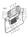
- the closure 3 comprises one on the side wall 4 of the lower part 1 fixed latch 5, the in the illustrated embodiment from a thin, resilient metal strip is bent.
- This nose has a substantially perpendicular to the side wall 4 protruding top 6 on which the Side wall 4 facing away from the free end of the latch 5 arc-shaped merges into an obliquely downward one Aufgleit Structure 7, to which an arc after section 8 deformed on the inside.
- the latch 5 facing downward Locking projection 9 from which one through the section 8 formed return 10 connects.
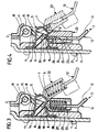
- the latch 5 is slightly elastic overall deformable, so that the locking projection 9 slightly can be moved elastically upwards.
- a plate-shaped Flap 12 pivotally mounted, the Pivot axis 11 opposite edge section 13 of the side wall 4 is bent away so that the gripping the flap 12 is relieved at its free end.
- the flap 12 is essentially U-shaped, the two lateral edge sections forming arms 14, at its free end to a bearing eye 15 are bent, which defines a pivot axis 11 Take up bearing shaft 16. This is your turn stored on cover 2 by suitable eyelets.
- Is located between the two arms 14 in the flap 12 shows a section 17 with one on the pivot axis 11 subsequent wider area 18 and one of the narrower region 19 further away from the pivot axis 11.
- Parallel to the side edge 20 of the narrower area 19 run elongated holes 21 in the flap.
- the width of the corresponds to wider area 18 and that on its side walls continuous longitudinal grooves from top to bottom 23, into which the material of the flap 12 enters, when the locking body 22 from the open side of the Section 17 is inserted into this.
- the flap material thus forms together with the longitudinal grooves 23 a longitudinal guide for the slidable in section 17 stored locking body 22.
- a notch 24 which is immersed in the longitudinal grooves 23, which has an oblique sliding surface on its underside 25 and on its top one transverse to the direction of displacement of the locking body 22 extending stop surface 26 has.
- This catch 24 is elastic can be pushed out of the longitudinal groove 23, this is due to the Self-elasticity of the locking body material 22 allows. It is aligned with the longitudinal grooves 23 in the flap, so that when inserting the locking body 22 in the Section 17 the notches 24 first through the system the flap on the sliding surface 25 from the longitudinal grooves 23 can be lifted out elastically after insertion of the locking body but spring back elastically and then in engage the elongated holes 21. This will make the locking body 22 held captive in the flap, because at the movement of the locking body towards the open The stop surfaces 26 abut the end of the cutout 17 the notches 24 against the ends of the elongated holes 21 and prevent further movement of the locking body.
- the locking body 22 In the area between the elongated holes 21 is in the locking body 22 a cuboid, open towards the bottom Receiving chamber 27 arranged in the shown in the Embodiment three coil springs 28 side by side be introduced. On the one hand, these are supported on the locking body 22 and on the other hand on the lower edge 29 of section 17 and move the Snap body 22 to the open end of the cutout 17.
- the coil springs 28 are preferably preloaded, when the locking body 22 in the cutout 17th is inserted.
- the receiving chamber 27 is so large that several such coil springs 28 side by side in it Find space, but the user can limit the number of coil springs actually used accordingly the desired spring characteristics vary, that states it is easily possible to enter the receiving chamber even use a single coil spring.
- the assembly of the flap is therefore extraordinary simple, because it is enough, in the locking body the desired number of coil springs 28 with the desired one Use spring characteristics and then the Push the locking body into the cutout 17 until the Snap catches 24 into the elongated holes 21, then connect them can the flap in the same way on Lids can be set like this with conventional ones Flaps was the case.
- the top 30 of the locking body 22 is a locking projection trained and rounded. Your location is at relaxed coil springs 28 chosen so that when Swiveling the flap 12 in the closed position the top 30 on the sliding surface 7 of the latch 5 to the system comes. This will cause the Flap 12 of the locking body 22 against the action of Coil spring 28 inserted into the cutout 17, see above that the top 30 of the locking body 22 the locking projection 9 can happen. Once this is done the helical spring 28 presses the locking body 22 with its Top 30 in the recess 10 of the locking lug 5 into it so that the flap 12 is now in the closed position is fixed. The coil spring 28 (or if necessary the coil springs 28) tension in this Position the lid 2 against the lower part 1, the clamping force depends on the characteristics of the coil springs 28 and their number.
- the spring travel of the coil springs 28 can be relatively large be trained so that it is also possible against the Force of the coil springs 28 slightly from the cover Lift off the lower part. This can be important if an overpressure builds up in the container, the described resilient construction of the latching body 22 then leads to a safety valve effect that the Relief of overpressure enables.
Landscapes
- Health & Medical Sciences (AREA)
- Life Sciences & Earth Sciences (AREA)
- Veterinary Medicine (AREA)
- Animal Behavior & Ethology (AREA)
- Engineering & Computer Science (AREA)
- Public Health (AREA)
- Surgery (AREA)
- General Health & Medical Sciences (AREA)
- Heart & Thoracic Surgery (AREA)
- Molecular Biology (AREA)
- Medical Informatics (AREA)
- Biomedical Technology (AREA)
- Nuclear Medicine, Radiotherapy & Molecular Imaging (AREA)
- Epidemiology (AREA)
- Mechanical Engineering (AREA)
- Closures For Containers (AREA)
Abstract
Claims (16)
- Récipient stérile pour applications médicales comprenant une partie inférieure (1) en forme de cuve et un couvercle (2) à poser de manière étanche sur celle-ci, qui peut être serré par une fermeture (3) contre la partie inférieure (1), la fermeture (3) comportant un rabat (12), susceptible de pivoter entre une position d'ouverture et une position de fermeture et muni d'une saillie à encliqueter (30) qui est conçue sous forme de corps à encliqueter séparé du rabat (12), et un taquet d'arrêt (5) muni d'un creux destiné à recevoir la saillie à encliqueter (30) dans la position de fermeture du rabat (12), caractérisé en ce que la saillie à encliqueter (30) dans le rabat (12) peut coulisser de manière souple dans une glissière (23) dans une direction dans laquelle ladite saillie sort du creux (10) du taquet d'arrêt (5).
- Récipient stérile selon la revendication 1, caractérisé en ce que la glissière (23) est ouverte au niveau d'une extrémité et est fermée au niveau de l'autre extrémité.
- Récipient stérile selon la revendication 2, caractérisé en ce que l'extrémité ouverte est orientée vers l'axe de pivotement (11) du rabat (12).
- Récipient stérile selon l'une quelconque des revendications 1 à 3, caractérisé en ce que la glissière est formée par les bordures d'une découpe (17) réalisée dans le rabat (12), lesquelles entrent en prise dans des rainures longitudinales (23) latérales du corps à encliqueter (22).
- Récipient stérile selon l'une quelconque des revendications 2 à 4, caractérisé en ce que le corps à encliqueter (22) est bloqué de manière imperdable dans la glissière (23) par l'intermédiaire d'une butée (24) qui, au moment de l'introduction du corps à encliqueter (22) dans la glissière (23), peut être amenée de manière souple hors de prise.
- Récipient stérile selon la revendication 5, caractérisé en ce que la butée (24) est conçue sous forme d'organe d'arrêt (24) souple, qui s'engage dans un évidement (21) parallèle à la glissière (23).
- Récipient stérile selon l'une quelconque des revendications 1 à 6, caractérisé en ce que des moyens à ressort (28) sont agencés entre le corps à encliqueter (22) et le rabat (12).
- Récipient stérile selon la revendication 7, caractérisé en ce que le rabat (12) et/ou le corps à encliqueter (22) comportent un logement (27) pour les moyens à ressort (28).
- Récipient stérile selon la revendication 8, caractérisé en ce que le logement (27) est dimensionné de telle sorte qu'il peut recevoir plusieurs ressorts de compression (28) juxtaposés, formant les moyens à ressort.
- Récipient stérile selon l'une quelconque des revendications 7 à 9, caractérisé en ce que les moyens à ressort (28) sont précontraints dans la position finale détendue.
- Récipient stérile selon l'une quelconque des revendications 1 à 10, caractérisé en ce que le corps à encliqueter (22) est logé dans le plan du rabat (12) de manière mobile en direction de l'axe de pivotement (11) de celui-ci.
- Récipient stérile selon la revendication 11, caractérisé en ce que le rabat (12) est conçu en forme de U avec deux branches (14), qui définissent l'axe de pivotement (11) au niveau de leurs extrémités libres et avec une découpe (17) centrale destinée à recevoir le corps à encliqueter (22).
- Récipient stérile selon l'une quelconque des revendications précédentes, caractérisé en ce que le taquet d'arrêt (5) est conçu de manière souple, de telle sorte que, au moment du pivotement du rabat (12), il s'écarte légèrement de la saillie à encliqueter (30) sur le rabat (12).
- Récipient stérile pour applications médicales comprenant une partie inférieure en forme de cuve et un couvercle à poser de manière étanche sur celle-ci, qui, au moyen d'une fermeture à appuyer et à détacher à nouveau, peut être serré de manière souple contre la partie inférieure lorsque la fermeture est mise en appui, selon l'une quelconque des revendications précédentes, caractérisé en ce que le couvercle (2), même si la fermeture (3) est mise en appui, peut être retiré à l'encontre de la force de fermeture exercée par les ressorts de la fermeture (3) sur une distance telle qu'il se forme une ouverture entre le couvercle (2) et la partie inférieure (1).
- Récipient stérile selon la revendication 14, caractérisé en ce que, lorsque le couvercle (2) est posé de manière étanche, ledit récipient est complètement fermé et son compartiment intérieur communique avec le milieu ambiant uniquement par une soupape d'admission.
- Récipient stérile selon la revendication 14 ou 15, caractérisé en ce que, au niveau du couvercle (2), est agencé un élément de levage, au niveau duquel le couvercle (2) peut être retiré de la partie inférieure (1) en forme de cuve à l'encontre de la force de fermeture exercée par les ressorts de la fermeture (3) mise en appui.
Applications Claiming Priority (3)
| Application Number | Priority Date | Filing Date | Title |
|---|---|---|---|
| DE19755532 | 1997-12-13 | ||
| DE1997155532 DE19755532C2 (de) | 1997-12-13 | 1997-12-13 | Sterilcontainer für medizinische Zwecke |
| PCT/EP1998/008068 WO1999030630A1 (fr) | 1997-12-13 | 1998-12-10 | Recipient sterile pour applications medicales |
Publications (2)
| Publication Number | Publication Date |
|---|---|
| EP1037568A1 EP1037568A1 (fr) | 2000-09-27 |
| EP1037568B1 true EP1037568B1 (fr) | 2003-10-01 |
Family
ID=7851857
Family Applications (1)
| Application Number | Title | Priority Date | Filing Date |
|---|---|---|---|
| EP98963559A Expired - Lifetime EP1037568B1 (fr) | 1997-12-13 | 1998-12-10 | Recipient sterile pour applications medicales |
Country Status (4)
| Country | Link |
|---|---|
| US (1) | US6371326B1 (fr) |
| EP (1) | EP1037568B1 (fr) |
| DE (1) | DE19755532C2 (fr) |
| WO (1) | WO1999030630A1 (fr) |
Families Citing this family (44)
| Publication number | Priority date | Publication date | Assignee | Title |
|---|---|---|---|---|
| DE202005021090U1 (de) * | 2005-05-27 | 2007-04-05 | Ermis, Mehmet | Sterilbehälter |
| FR2890865B1 (fr) * | 2005-09-21 | 2007-11-23 | Gred Sa | Enceinte de desinfection d'instruments medicaux. |
| FR2899480B1 (fr) * | 2006-04-10 | 2008-10-03 | Gred Sa | Systeme de desinfection d'instruments medicaux |
| FR2914555B1 (fr) * | 2007-04-05 | 2009-06-26 | Germitec Soc Par Actions Simpl | Dispositif de conditionnement d'un appareil medical de type sonde. |
| FR2914554B1 (fr) * | 2007-04-05 | 2009-07-17 | Germitec Soc Par Actions Simpl | Procede de suivi de l'uitilisation d'un appareil medical. |
| DE202010005089U1 (de) | 2010-04-15 | 2010-07-01 | Nopa Instruments Medizintechnik Gmbh | Sterilcontainer für medizinische Zwecke |
| DE102010036489A1 (de) * | 2010-07-19 | 2012-01-19 | Aesculap Ag | Behälterunterteil und Behälteroberteil eines Sterilbehälters und Sterilbehälter |
| US8602256B2 (en) * | 2011-03-28 | 2013-12-10 | Yao-Hung Wang | Quick open structure for a tool box |
| DE202011104615U1 (de) | 2011-08-17 | 2011-11-10 | Innovations-Medical Gmbh | Verschluss für Sterilcontainer |
| DE202012002487U1 (de) | 2012-03-09 | 2012-05-07 | Innovations-Medical Gmbh | Containerverschluss |
| CN103359376B (zh) * | 2012-03-27 | 2016-02-10 | 海洋王照明科技股份有限公司 | 箱体锁紧装置 |
| DE202012102803U1 (de) | 2012-07-26 | 2013-10-29 | Thomas Tontarra Grundstücksverwaltungs GmbH & Co. KG | Sterilcontainer |
| US8976536B2 (en) * | 2013-04-10 | 2015-03-10 | Lenovo Enterprise Solutions (Singapore) Pte. Ltd. | Latching cam handle assembly for securing mated circuit boards |
| DE102014215353B4 (de) | 2014-08-04 | 2025-03-06 | Aesculap Ag | Antimikrobieller Sterilcontainer |
| DE102014117517A1 (de) * | 2014-11-28 | 2016-06-02 | Aesculap Ag | Mediznischer Sterilbehälter mit Sicherheitsbelüftungsventil |
| DE102017108411A1 (de) * | 2017-04-20 | 2018-10-25 | Aesculap Ag | Behälter mit Verschlusssystem |
| AU201717615S (en) | 2017-06-12 | 2018-01-15 | Yeti Coolers | Container |
| USD872485S1 (en) | 2017-06-12 | 2020-01-14 | Yeti Coolers, Llc | Container |
| US11685573B2 (en) | 2017-06-12 | 2023-06-27 | Yeti Coolers, Llc | Carry strap for container |
| WO2018231826A1 (fr) * | 2017-06-12 | 2018-12-20 | Yeti Coolers, Llc | Contenant et système de verrouillage |
| USD873020S1 (en) | 2017-06-12 | 2020-01-21 | Yeti Coolers, Llc | Container |
| US12108853B2 (en) | 2019-01-06 | 2024-10-08 | Yeti Coolers, Llc | Luggage system |
| US11976498B2 (en) | 2017-06-12 | 2024-05-07 | Yeti Coolers, Llc | Container and latching system |
| USD869160S1 (en) | 2017-06-12 | 2019-12-10 | Yeti Coolers, Llc | Container |
| USD838984S1 (en) | 2017-06-12 | 2019-01-29 | Yeti Coolers, Llc | Container |
| USD838983S1 (en) | 2017-06-12 | 2019-01-29 | Yeti Coolers, Llc | Container |
| USD840150S1 (en) | 2017-06-12 | 2019-02-12 | Yeti Coolers, Llc | Container |
| USD872478S1 (en) | 2017-06-12 | 2020-01-14 | Yeti Coolers, Llc | Container |
| USD907445S1 (en) | 2018-12-11 | 2021-01-12 | Yeti Coolers, Llc | Container accessories |
| USD904829S1 (en) | 2018-12-11 | 2020-12-15 | Yeti Coolers, Llc | Container accessories |
| US12225993B2 (en) | 2019-01-06 | 2025-02-18 | Yeti Coolers, Llc | Luggage system |
| MX2021008199A (es) | 2019-01-06 | 2021-11-12 | Yeti Coolers Llc | Sistema de equipaje. |
| CN111468494B (zh) * | 2020-06-16 | 2021-10-22 | 伊魅仕彩妆(深圳)有限公司 | 一种化妆品生产用瓶体清洁消毒装置 |
| USD951643S1 (en) | 2020-06-30 | 2022-05-17 | Yeti Coolers, Llc | Luggage |
| USD954436S1 (en) | 2020-06-30 | 2022-06-14 | Yeti Coolers, Llc | Luggage |
| USD963344S1 (en) | 2020-06-30 | 2022-09-13 | Yeti Coolers, Llc | Luggage |
| USD961926S1 (en) | 2020-06-30 | 2022-08-30 | Yeti Coolers, Llc | Luggage |
| DE102020127370A1 (de) | 2020-10-16 | 2022-04-21 | Innovations-Medical Gmbh | Verschlussvorrichtung für Sterilbehälter sowie Sterilbehälter mit einer derartigen Verschlussvorrichtung |
| USD994438S1 (en) | 2020-12-16 | 2023-08-08 | Yeti Coolers, Llc | Container |
| USD985937S1 (en) | 2020-12-16 | 2023-05-16 | Yeti Coolers, Llc | Container |
| USD960648S1 (en) | 2020-12-16 | 2022-08-16 | Yeti Coolers, Llc | Container accessory |
| DE102021110158A1 (de) | 2021-04-21 | 2022-10-27 | Ermis Medizintechnik E.K. | Griff für einen Sterilisationsbehälter |
| DE202021102136U1 (de) | 2021-04-21 | 2021-05-05 | Ermis Medizintechnik E.K. | Griff für einen Sterilisationsbehälter |
| US11738914B2 (en) | 2021-11-18 | 2023-08-29 | Yeti Coolers, Llc | Container and latching system |
Family Cites Families (15)
| Publication number | Priority date | Publication date | Assignee | Title |
|---|---|---|---|---|
| DE8213349U1 (de) * | 1982-09-09 | Aesculap-Werke Ag Vormals Jetter & Scheerer, 7200 Tuttlingen | Sterilisierbehälter für ärztliche Instrumente | |
| US233195A (en) * | 1880-10-12 | G-ilbebt w | ||
| US1382499A (en) * | 1921-06-21 | Radiatob-cap | ||
| GB190901818A (en) * | 1909-01-25 | 1909-04-15 | George Downing | Improvements in Fastenings for the Lids of Airtight and Watertight Metal Boxes. |
| US1089066A (en) * | 1913-07-30 | 1914-03-03 | Albert W Meyer | Steam-cooker. |
| US1483953A (en) * | 1922-11-01 | 1924-02-19 | Lilius B Rainey | Cap for liquid receptacles |
| DE1586580C3 (de) * | 1967-06-03 | 1975-07-10 | Drägerwerk AG, 2400 Lübeck | Plombierung für kniehebelartige Verschlüsse von Behältern, insbesondere für Atemschutzgeräte |
| US4349118A (en) * | 1975-12-15 | 1982-09-14 | Roger S. Sanderson | Sterilizing and storing medical items |
| US4331257A (en) * | 1980-12-18 | 1982-05-25 | Aesculap-Werke Aktiengesellschaft Vormals Jetter & Scheerer | Closure for a container having additional securing means |
| US4562047A (en) * | 1983-12-19 | 1985-12-31 | American Sterilizer Company | Indicator seal and sterilizer container |
| DE3542404C1 (de) | 1985-11-30 | 1987-06-11 | Aesculap Werke Ag | Sterilisierbehaelter fuer chirurgische Instrumente |
| US5193759A (en) * | 1990-12-28 | 1993-03-16 | Eastman Kodak Company | Film or paper cassette |
| DE4127893C2 (de) * | 1991-08-22 | 2002-04-04 | Daimlerchrysler Aerospace Ag | Spannvorrichtung zur Herstellung einer wieder lösbaren Verbindung zweier Teile |
| JPH0758015B2 (ja) * | 1993-02-18 | 1995-06-21 | タキゲン製造株式会社 | 掛金装置 |
| JP2590049B2 (ja) * | 1994-10-24 | 1997-03-12 | タキゲン製造株式会社 | 掛金装置 |
-
1997
- 1997-12-13 DE DE1997155532 patent/DE19755532C2/de not_active Expired - Lifetime
-
1998
- 1998-12-10 WO PCT/EP1998/008068 patent/WO1999030630A1/fr not_active Ceased
- 1998-12-10 EP EP98963559A patent/EP1037568B1/fr not_active Expired - Lifetime
-
2000
- 2000-06-12 US US09/592,081 patent/US6371326B1/en not_active Expired - Lifetime
Also Published As
| Publication number | Publication date |
|---|---|
| EP1037568A1 (fr) | 2000-09-27 |
| DE19755532A1 (de) | 1999-06-24 |
| US6371326B1 (en) | 2002-04-16 |
| WO1999030630A1 (fr) | 1999-06-24 |
| DE19755532C2 (de) | 2001-07-12 |
Similar Documents
| Publication | Publication Date | Title |
|---|---|---|
| EP1037568B1 (fr) | Recipient sterile pour applications medicales | |
| DE69710260T2 (de) | Durch lateralen Druck lösbare Schnalle mit verbesserter Verriegelungsvorrichtung | |
| EP3658062B1 (fr) | Fermeture de récipient | |
| EP0108858A1 (fr) | Malle avec une serrure de mise en tension | |
| DE2749946A1 (de) | Kniehebel-abgabeverschluss | |
| DE29516306U1 (de) | Schließvorrichtung für Behälter, wie Koffer, Taschen o.dgl. | |
| DE3710049C2 (fr) | ||
| DE69109559T2 (de) | Mit einem einteiligen Verschluss versehener Behälter. | |
| DE1947493U (de) | Betaetigungsvorrichtung fuer aerosolbehaelter. | |
| EP0263430A2 (fr) | Toit pare-soleil | |
| DE202021104825U1 (de) | Sterilcontainer | |
| DE29912563U1 (de) | Öffnungsvorrichtung für eine Schranktür | |
| DE2644947A1 (de) | Verschlusseinrichtung, welche durch druck betaetigbar ist | |
| DE10357285A1 (de) | Haubenverschluß für eine Motor- oder Kofferraumhaube | |
| DE69311351T2 (de) | Verriegelungsvorrichtung für lösbare teile | |
| DE19613035A1 (de) | Griffstück für eine Spritze | |
| DE69302032T2 (de) | Verbindungselement mit einem Bauteil, insbesondere zur Herstellung einer Verbindung zu einem anderen Bauteil | |
| DE29722075U1 (de) | Sterilcontainer für medizinische Zwecke | |
| DE2904290A1 (de) | Verschlussanordnung | |
| DE29922447U1 (de) | Abdichtbarer Behälter | |
| EP4132410B1 (fr) | Mécanisme de fermeture avec dispositif de verrouillage pour récipients stériles, et récipient stérile le comprenant | |
| DE8437898U1 (de) | Behälter für langgestreckte diagnostische Testträger | |
| DE2611077C2 (de) | Verschluß für klapp- oder schwenkbare Bordwandkonstruktionen | |
| DE102020107404A1 (de) | Behälterverschluss und Behälter | |
| EP0767106A1 (fr) | Récipient en matière plastique avec couvercle et fermeture par encliquetage |
Legal Events
| Date | Code | Title | Description |
|---|---|---|---|
| PUAI | Public reference made under article 153(3) epc to a published international application that has entered the european phase |
Free format text: ORIGINAL CODE: 0009012 |
|
| 17P | Request for examination filed |
Effective date: 20000607 |
|
| AK | Designated contracting states |
Kind code of ref document: A1 Designated state(s): ES FR GB IT |
|
| RBV | Designated contracting states (corrected) |
Designated state(s): ES FR GB IT |
|
| GRAH | Despatch of communication of intention to grant a patent |
Free format text: ORIGINAL CODE: EPIDOS IGRA |
|
| GRAS | Grant fee paid |
Free format text: ORIGINAL CODE: EPIDOSNIGR3 |
|
| GRAA | (expected) grant |
Free format text: ORIGINAL CODE: 0009210 |
|
| AK | Designated contracting states |
Kind code of ref document: B1 Designated state(s): ES FR GB IT |
|
| REG | Reference to a national code |
Ref country code: GB Ref legal event code: FG4D Free format text: NOT ENGLISH |
|
| GBT | Gb: translation of ep patent filed (gb section 77(6)(a)/1977) |
Effective date: 20031112 |
|
| PG25 | Lapsed in a contracting state [announced via postgrant information from national office to epo] |
Ref country code: ES Free format text: LAPSE BECAUSE OF FAILURE TO SUBMIT A TRANSLATION OF THE DESCRIPTION OR TO PAY THE FEE WITHIN THE PRESCRIBED TIME-LIMIT Effective date: 20040112 |
|
| ET | Fr: translation filed | ||
| PLBE | No opposition filed within time limit |
Free format text: ORIGINAL CODE: 0009261 |
|
| STAA | Information on the status of an ep patent application or granted ep patent |
Free format text: STATUS: NO OPPOSITION FILED WITHIN TIME LIMIT |
|
| 26N | No opposition filed |
Effective date: 20040702 |
|
| REG | Reference to a national code |
Ref country code: FR Ref legal event code: PLFP Year of fee payment: 18 |
|
| REG | Reference to a national code |
Ref country code: FR Ref legal event code: PLFP Year of fee payment: 19 |
|
| REG | Reference to a national code |
Ref country code: FR Ref legal event code: PLFP Year of fee payment: 20 |
|
| PGFP | Annual fee paid to national office [announced via postgrant information from national office to epo] |
Ref country code: FR Payment date: 20171219 Year of fee payment: 20 |
|
| PGFP | Annual fee paid to national office [announced via postgrant information from national office to epo] |
Ref country code: GB Payment date: 20171221 Year of fee payment: 20 Ref country code: IT Payment date: 20171218 Year of fee payment: 20 |
|
| REG | Reference to a national code |
Ref country code: GB Ref legal event code: PE20 Expiry date: 20181209 |
|
| PG25 | Lapsed in a contracting state [announced via postgrant information from national office to epo] |
Ref country code: GB Free format text: LAPSE BECAUSE OF EXPIRATION OF PROTECTION Effective date: 20181209 |