EP1037729B1 - Stützteller für schleifartikel und anwendungsverfahren - Google Patents
Stützteller für schleifartikel und anwendungsverfahren Download PDFInfo
- Publication number
- EP1037729B1 EP1037729B1 EP98911514A EP98911514A EP1037729B1 EP 1037729 B1 EP1037729 B1 EP 1037729B1 EP 98911514 A EP98911514 A EP 98911514A EP 98911514 A EP98911514 A EP 98911514A EP 1037729 B1 EP1037729 B1 EP 1037729B1
- Authority
- EP
- European Patent Office
- Prior art keywords
- backup pad
- abrasive article
- opening
- boss
- section
- Prior art date
- Legal status (The legal status is an assumption and is not a legal conclusion. Google has not performed a legal analysis and makes no representation as to the accuracy of the status listed.)
- Expired - Lifetime
Links
Images


Classifications
-
- B—PERFORMING OPERATIONS; TRANSPORTING
- B24—GRINDING; POLISHING
- B24B—MACHINES, DEVICES, OR PROCESSES FOR GRINDING OR POLISHING; DRESSING OR CONDITIONING OF ABRADING SURFACES; FEEDING OF GRINDING, POLISHING, OR LAPPING AGENTS
- B24B45/00—Means for securing grinding wheels on rotary arbors
- B24B45/006—Quick mount and release means for disc-like wheels, e.g. on power tools
-
- B—PERFORMING OPERATIONS; TRANSPORTING
- B24—GRINDING; POLISHING
- B24D—TOOLS FOR GRINDING, BUFFING OR SHARPENING
- B24D13/00—Wheels having flexibly-acting working parts, e.g. buffing wheels; Mountings therefor
- B24D13/20—Mountings for the wheels
-
- B—PERFORMING OPERATIONS; TRANSPORTING
- B24—GRINDING; POLISHING
- B24D—TOOLS FOR GRINDING, BUFFING OR SHARPENING
- B24D7/00—Bonded abrasive wheels, or wheels with inserted abrasive blocks, designed for acting otherwise than only by their periphery, e.g. by the front face; Bushings or mountings therefor
- B24D7/16—Bushings; Mountings
-
- B—PERFORMING OPERATIONS; TRANSPORTING
- B24—GRINDING; POLISHING
- B24D—TOOLS FOR GRINDING, BUFFING OR SHARPENING
- B24D9/00—Wheels or drums supporting in exchangeable arrangement a layer of flexible abrasive material, e.g. sandpaper
- B24D9/08—Circular back-plates for carrying flexible material
- B24D9/085—Devices for mounting sheets on a backing plate
Definitions
- the present invention relates generally to backup pads for use with abrasive articles, and more particularly to backup pads having a quick-release mechanism.
- a backup pad to support abrasive articles, such as abrasive sheets which may be converted into any form, such as circular discs.
- the backup pad may be a hand-held pad for manual operation, or a backup pad for use with a power tool such as a rotary or orbital sander.
- a power tool such as a rotary or orbital sander.
- the backup pad is for use on a rotary power tool, it is necessary to mount the backup pad to the rotary tool in a secure manner to prevent relative rotation between the backup pad and the power tool drive shaft.
- the backup pad is bolted to or is threaded engagement with the drive shaft on the power tool.
- EP 397624 upon which the preamble of Claim 1 is based, which discloses a back-up pad for releasably engaging an abrasive article.
- the back-up pad includes releasable engagement means on the front surface of the back-up pad and a mounting boss on the rear surface.
- the mounting boss faces away from the back-up pad and includes a circular threaded opening for threaded engagement with a drive shaft.
- Other arrangements for securing the backup pad to the drive shall of the rotary tool have also been used. (See for example, U.S. Patent No, 3,270,467.)
- the backup pad for releasably engaging an abrasive article.
- the backup pad comprises a body having a front surface and a back surface, releasable engagement means provided on the front surface for releasably engaging an abrasive article, and a mounting boss provided on the rear surface.
- the mounting boss includes a first end facing away from the body and an opening in the first end of the boss.
- the opening is formed by an inner surface generally perpendicular to the body and defining a non-circular cross section.
- the opening includes elastic means for releasably engaging a drive shaft mounted in the opening.
- the inner surface of the opening may a polygonal cross section, a regular polygonal cross section, or a hexagonal cross-section.
- the elastic engaging means in the opening may comprise an elastic ring retained in a groove in the inner surface.
- the elastic ring may be, for example, an o-ring or a snap ring.
- the releasable engagement means may comprise a vinyl surface adapted for releasable engagement with an adhesive layer on an abrasive article, a plurality of hooking stems adapted for releasable engagement with a loop material on an abrasive article, or a loop material adapted for releasable engagement with a plurality of hooking stems on an abrasive article.
- the present invention also provides, as defined by Claim 12, a quick release system for releasably attaching a backup pad on a mounting shaft.
- the system comprises a backup pad and a mounting shaft.
- the backup pad is as described above.
- the mounting shaft includes a first end and a second end. The first end includes a groove for engagement with the elastic means.
- the mounting shaft also includes a mating portion defining a cross section corresponding to the opening cross section in the boss.
- the present invention also provides a method of refining a surface of an object with a plurality of abrasive articles as defined by Claim 13.
- the first abrasive article may have a composition different from the second abrasive article.
- the first and second backup pads preferably are mounted to the power tool by the quick release system described above.
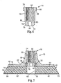
- FIG. 1 is a side view of a preferred embodiment of a backup pad 10 according to the present invention.
- Backup pad 10 includes a backing plate 12 having a front surface 14 and rear surface 16.
- a boss 18 extends from the rear surface 16 of the backing plate 12.
- Boss 18 includes a first end 20 remote from the backing plate 12 and a second end 22 adjacent the backing plate 12.
- Boss 18 is preferably unitary with the backing plate 12. Alternatively, boss 18 and backing plate 12 may be two pieces joined or bonded together.
- the backup pad 10 also includes a resilient pad 40 which has a front surface 42 and a rear surface 44.
- the resilient pad 40 is attached at rear surface 44 to the front surface 14 of the backing plate 12.
- the backup pad also includes an engagement element 50 attached to the front surface 42 of the resilient pad.
- Engagement element 50 includes a front surface for releasable engagement with an abrasive article and a rear surface 54 which is attached to the front surface of the resilient pad.
- boss 18 includes an opening 24 at the first end 20.
- the boss opening 24 is configured for mounting on a drive shaft 70, which will be described in detail below.
- the opening 24 includes flat walls 26 which join at corners 28.
- the walls define a hexagonal cross-sectional opening 24 in the boss 18.
- the opening also includes a groove 30 in which is retained an o-ring 36.
- the groove 30 may be molded or machined into the boss 18.
- a recess may be formed in the opening 24 in boss 18 which opens to the front surface 14 of the backing plate 12.
- Annular ring 31 may then be press fit part way into this recess thereby forming the groove 30 to retain the o-ring 36.
- the backup pad 10 may optionally be configured to allow coolant or lubricant to flow through the backup pad to the surface being abraded or finished.
- the resilient pad 40 includes water passage 46 aligned with the opening 24 in the boss 18, and the engagement element 50 includes a water passage 56 aligned with the pad water passage 46.
- the coolant flow may also be routed through passages which are directed away from the central axis.
- FIG. 4 illustrates a side view of a preferred embodiment of a mounting shaft 70 for use with the backup pad described herein.
- Mounting shaft 70 may be a separate element that can be attached to a drive shaft of conventional power tools used with the backup pad 10.
- drive shaft 70 may be a permanent element of a power tool.
- the mounting shaft 70 includes a first end 72 which is configured to fit into the opening 24 in boss 18 of the backup pad 10.
- Shaft 70 also includes second end 74 for attachment to the drive shaft of a power tool (not illustrated).
- Adjacent first end 72 is a tapered portion 76 to facilitate engagement of the drive shaft 70 into the opening 24 in the boss 18 and to facilitate engagement with the o-ring 36.
- Adjacent to and rearward from the taper 76 is a flat portion.
- groove 80 which defines the bottom end of groove 80.
- Rearward of groove 80 is a taper 82 which transitions into flat walls 84 and corners 86 on the mounting shaft 70.
- the walls 84 and corners 86 are configured for close fit with the walls 26 and corners 28 of the opening in the boss on the backup pad.
- the walls 84 thus define a mating portion with a cross section corresponding to the cross section of opening 24 in the boss 18.
- the groove 80 is configured for a snap engagement with the o-ring 36 in the backup pad 10.
- Rearward of the flat walls 84 is shoulder 88.
- Shank 90 extends rearward from the shoulder 88 and terminates at second end 74 of the mounting shaft 70.
- the mating portion of the shaft 70 defined by walls 84 may be tapered so as to be smaller near the first end 72.
- the opening 24 in the boss of the backup pad may have a corresponding taper.
- the mounting shaft 70 includes a threaded inner diameter surface 92 for engagement with the drive shaft on the power tool.
- Mounting shaft 70 can optionally include water passage 94 for allowing coolant and/or lubricant to be provided through the mounting shaft 70 and the opening in the backup pad 10 onto the surface being abraded or polished.
- Figure 7 illustrates the backup pad 10 mounted onto the drive shaft 70.
- the drive shaft 70 and opening 24 in the boss 18 are configured for close engagement with one another to minimize relative rotation between the backup pad 10 and the mounting shaft 70 during operation.
- the material and size of boss 18 and mounting shaft 70 are selected to withstand the torque imparted during use of the backup pad 10 with a power tool.
- Preferred materials for boss 18 include metals such as aluminum and steel, and plastics such as nylon.
- Preferred materials for mounting shaft 70 include metals such as steel and aluminum, graphites, and plastic.
- Groove 80 engages with o-ring 36 to prevent inadvertent release of the backup pad 10 from the mounting shaft 70, while allowing the backup pad to be easily removed from the drive shaft without tools simply by pulling or pushing the backup pad 10 away with the drive shaft with enough force to overcome the snap fit between the o-ring 36 and groove 80.
- the distance between the shoulder 88 and groove 80 on the drive shaft 70 can be chosen such that first end 20 of the boss 18 on the backup pad engages with the shoulder 88 on the drive shaft 70 when groove 80 is engaged with the o-ring 36.
- taper 76 on the drive shaft 70 facilitates engagement of the mounting shaft with the o-ring, and expands the o-ring as the drive shaft 70 is inserted into the opening in the boss 18.
- the resilient o-ring 36 then snaps back to a small diameter and engages with the groove 80 in the mounting shaft 70
- the O-ring 36 may instead be any elastic member that can releasably engage with groove 80 on shaft 70, such as a snap ring, C-clip, or the like. These can be made of any suitable material such metal, rubber, vinyl, or composites selected to allow the elastic member to expand elastically without significant permanent deformation, and then contract into the groove in the shaft. It is preferred that the elastic member be retained with the groove as illustrated. The outermost wall of the groove thereby limits the expansion of the elastic member during use. This will prolong the life of the elastic member by reducing the amount of permanent stretch or growth. caused during use.
- the dimensions of the walls on the drive shaft 70 relative to the opening 24 in the boss 18 should be selected to minimize relative rotation between the backup pad and the drive shaft during use, while allowing easy mounting and dismounting of the backup pad from the mounting shaft 70.
- Arrangements for the cross-sectional shape of the mounting shaft 70 and opening 24 other than hexagonal may be chosen.
- Preferred arrangements include any polygonal cross-sectional shapes.
- 3, 4, or 7 or more walls may be used on the mounting shaft. 70 and in the opening 24 in the boss 18.
- a regular polygon is used, that is all walls are the same size, to reduce the need to index the backup pad 10 at any particular angular orientation relative to the mounting shaft 70.
- a non-regular or non-symmetrical arrangement may be used if desired.
- any non-polygonal arrangement may be used for the cross-sectional shape of the shaft and opening, except for circular, to provide an arrangement in which the backup pad. does not rotate relative to the drive shaft. Therefore, what is required is that the opening 24 and the corresponding portion of the mounting shaft 70 be non-cylindrical, thereby providing a fit to prevent relative rotation between the backup pad and the shaft.
- Pad 40 and backing plate 12 may be an integral, unitary element, rather than of two-piece construction as illustrated herein.
- boss 18 may be integral and unitary with plate 12, or may be a separate part joined thereto.
- resilient pad 40 is preferably a resilient material such as a flexible foam, for example, polyurethane, polyester, polyester-urethane, polyether-urethane, a natural or artificial rubber such as a polybutadiene, polyisoprene, EPDM polymer, polyvinylchloride (PVC), polychloroprene, or styrene/butadiene copolymer.
- the foam can be open or closed cell.
- Additives, such as coupling agents, toughening agents, curing agents, antioxidants, reinforcing materials, and the like can be added to the foam formulation to achieve the desired characteristics. Dyes, pigments, fillers, anti-static agents, fire retardants, and scrim can also be added to the foam.
- Particularly useful foams include TDI (toluene diisocyanate)/polyester and MDI (methylene diphenyl diisocyanate)/polyester foams.
- a preferred foam is a resilient, open cell polyurethane foam formed as the reaction product of a polyether polyol and an aromatic polyisocyanate.
- the aromatic polyisocyanate includes methylene diphenyl diisocyante (MDI). Further details on this preferred foam are disclosed in WIPO International Patent Application Publication Number WO97/20662, (Keipert).
- One method for forming the backup pad 10 of the present invention is to form the resilient pad 40 in. situ within a mold in which the desired engagement element 50 and backing plate 12 have been placed.
- the engagement element 50 and backing plate 12 can be inserted in the mold either before the foam is injected into the mold or after the foam is injected but before it has completely cured. Alternately, the foam. can be cured and removed from the mold, after which the desired engagement element 50 and backing plate 12 are adhered to the front and rear surfaces 42, 44 of the resilient pad 40. It is also possible to include either one of the engagement element and backing plate in the mold, and subsequently adhere the other.
- Conventional foam machines useful for this method of backup pad manufacture generally come in two varieties.
- the first type is a "low pressure” machine which relies on a mechanical mixing device in the dispensing head to mix two component streams, which when mixed, react to create the foam.
- a second type of foam machine is a "high pressure” or impingement mixing machine. In this type of device, mixing is achieved by impingement of two high velocity component streams within the mixing chamber. Methods of using such foam machines are known in the art.
- pre-fabricated foam in sheet form can be converted, that is, cut to the desired final configuration of the pad 40.
- the engagement element 50 and the backing plate 12 are then laminated onto the pad 40.
- the engagement element 50 can be laminated onto the face of the foam sheeting with a suitable adhesive and then the laminated composite (foam and engagement element) can be converted to the desired shape.
- the hardness and other physical properties of the backup pad 10 and resilient pad 40 are tailored to the desired abrading application. For example, in polishing applications it may be desired to used a softer, more flexible material for the resilient pad 40. Conversely, in more severe polishing applications, it is typically desired to use a hard, stiffer material such as a hard rubber. Since the backup pad is designed for use with power tools, the backup pad and its components should be made from materials that are capable of withstanding the intended rotational speeds. Typical speeds for a power driven rotary tool are 5,000 to 15,000 rpm, although faster and slower speeds are also used.
- the resilient pad 40 may alternately be selected from other rigid materials such as plastic, metal, rubber, and the like.
- the engagement element 50 on the front surface 42 of the resilient pad 40 is adapted for releasably engaging abrasive articles, such as abrasive sheets.
- Preferred embodiments of attachment systems for engagement element 50 include mechanical fastening systems such as hook and loop systems, and adhesive systems.
- hooks for use as engagement element 50 to releasably engage loop materials on abrasive sheets include mushroom hooks, "J” hooks, stalks, and "T” hooks.
- Commercially available hooks useful for the present invention for releasably engaging loop-backed abrasives include various hooks available from manufacturers such as Kanebo Belltouch Ltd. (of Osaka, Japan), and Velcro Inc. (of Manchester, NH). Examples of other suitable embodiments of hooks for use as engagement element 50 are disclosed in U.S. Patent No. 5,505,747, "Method of Making an Abrasive Article, " (Chesley et al.).
- hook-engaging materials for use as engagement element 50 to releasably engage hook-backed abrasives include loop materials commonly known as stitched loop, brushed loop, formed loop; tricot loop, and the like.
- Commercially available loops useful for the present invention include various loops available from manufacturers such as Kanebo Belltouch Ltd. (of Osaka, Japan), Guilford Mills (of Greensboro, NJ), and Woodeaves, Ltd. (of Lancaster, England).
- a backup pad having a highly durable and preferred loop system is disclosed in U.S. Patent No. 5,692,949 (Sheffield et al.).
- either the hook component or the loop component can be on the backup pad Hooks adapted to releasably engage a complementary hook material, i.e., attachment systems where two hooks engage such as the system available under the trade designation of "Dual Lock” from 3M, can also be used for the backup pad of the present invention.
- Adhesive systems useful as engagement element 50 include pressure sensitive. adhesives.
- the abrasive sheet has a pre-coated layer of adhesive on the side opposite the abrasive coating.
- the backup pad typically includes a smooth surface such as vinyl or rubber as engagement element 50 for receiving the abrasive article.
- the adhesive layer on the abrasive article can be adhered to the complementary mating surface of the backup pad.
- the abrasive article can then be easily removed when desired.
- the arrangement of the adhesive and vinyl components on the abrasive article and backup pad may be reversed.
- One preferred PSA attachment system is the "Stikit" attachment system from 3M.
- Another adhesive attachment system includes the use of an adhesive commonly known as a "feathering adhesive".
- the abrasive article initially has no adhesive, e.g., PSA, thereon.
- the feathering adhesive is applied (typically sprayed) onto either the abrasive article backing or the surface of the backup pad, or both.
- the abrasive article is then releasably attached to the backup pad.
- the preferred engagement element 50 used for both feathering adhesives and PSAs is generally a smooth non-porous surface, such as vinyl, rubber, or metal, although other surfaces are suitable. In some feathering applications, cloth mating surfaces are preferred.
- adhesives suitable for both a PSA or a feathering adhesive include latex crepe, rosin, acrylic polymers and copolymers (e.g., polybutylacrylate), polyacrylate ester, vinyl ethers (e.g., polyvinyl n-butyl ether), vinyl acetate adhesives, alkyd adhesives, rubber adhesives (e.g., natural rubber, synthetic rubber, chlorinated rubber), and mixtures thereof.
- One preferred pressure sensitive adhesive is an isooctylacrylate:acrylic acid copolymer.
- the abrasive articles useful for attachment to the backup pad of the present invention are not particularly limited, although they generally will be a conformable sheet or sheet-like configuration for most applications. At least one major face of the abrasive article will have an abrasive coating thereon, or the abrasive coating, i.e., abrasive grains, can extend throughout the thickness of the article, such as in a lofty non-woven abrasive article.
- the abrasive articles usable in the invention include, but are not limited to, coated abrasive articles, structured abrasives, non-woven abrasives, slurry coated abrasive articles, buffing pads,. and polishing pads. These articles are known in the abrasives art.
- a preferred use for the back-up pad of the present invention is for glass polishing, for example, television screens, CRT screens, lenses, mirrors, and the like.
- a first abrasive article having a first abrasive grade is used to remove nicks and large scratches in the workpiece surface.
- This is followed by polishing with a second abrasive article having a second abrasive grade which has a smaller average particle size than the first abrasive article.
- This second abrasive article removes any scratches left by the first abrasive article.
- it is generally necessary to remove the first abrasive article from the backup pad and then attach the second abrasive article. Repeated removal and reapplication of an abrasive article can damage the article, such as by tearing, creasing, or shelling, thereby reducing the useful life of the abrasive article.
- an abrasive particle which might be freed from the first. abrasive article may be trapped, for example, in the. water passage, could then be dislodged during the second polishing step. This large abrasive particle tends to produce deep wild scratches in the workpiece surface which are unacceptable.
- the back-up pad having the quick release attachment system is extremely useful in overcoming many of the shortcomings of conventional backup pads.
- By removing the entire backup pad and abrasive article assembly the chance of having a large abrasive particle from the first abrasive article left at the workpiece surface is greatly reduced. Additionally, the need to remove and reapply abrasive articles to the backup pad; which may deteriorate the abrasive article, is minimized.
- a preferred method of using the back-up pad of the present invention would actually be to have one grinder or power tool and two back-up pads, with a first abrasive article on one pad and a second abrasive article on the other pad..
- the back-up pad having the first abrasive article thereon would be attached to the grinder and then polish the workpiece. Once a finish acceptable for that step has been achieved, the back-up pad would be removed from. the grinder and the other back-up pad having the second abrasive article thereon would be attached. The workpiece surface would then be polished with this second abrasive article.
- the back-up pad would be removed and the workpiece subjected to a third polishing step or a new workpiece would be retrieved. If a new workpiece is to be polished next, then the first back-up pad and abrasive article can be reattached to the grinder and the process is repeated.
- the backup pad is preferably adapted for use with a power tool, such as, for example, an orbital sander, random orbital sander, rotary sander, dual action sander, vibratory sander, and corner sander.
- the backup pad can be any shape which will adapt to the tool being used.
- Well known tool manufactures include Black & Decker, Ryobi. Porter Cable, DeWalt, Skil, Aro and Dynabrade.
- Usable shapes for backup pad 10 include circles, ellipses, rectangles (including squares), triangles, hexagons, and the like.
- the backup pad may optionally have holes and channels therein for collecting. dust, debris, and swarf, or for transporting coolant to the polishing interface, as is well known in the art.
- the backup pad 10 is generally between about 2.5 cm and 30 cm in diameter (measured across the longest dimension), preferably between about 7.5 and 20 cm.
- the thickness of the backup pad is selected to provide the desired properties from the backup pad and is generally equal throughout the pad, although there may be some instances where a tapered or sectional backup pad may be desired.
- the backup pad is generally between about 0.5 cm and 10 cm thick, preferably between about 0.9 and 5 cm.
- the peripheral side walls or edges of the can be perpendicular or at an angle to provide a tapered pad. Backup pads larger or smaller than those just described also are within the scope of the present invention..
Landscapes
- Engineering & Computer Science (AREA)
- Mechanical Engineering (AREA)
- Polishing Bodies And Polishing Tools (AREA)
- Constituent Portions Of Griding Lathes, Driving, Sensing And Control (AREA)
Claims (14)
- Stützteller (10) zum lösbaren Festhalten eines Schleifartikels, wobei der Stützteller aufweist:wobei die Befestigungsnabe (18) ein von dem Körper (40) weg gerichtetes erstes Ende (20) und eine Öffnung in dem ersten Ende (20) der Nabe (18) aufweist, dadurch gekennzeichnet, daß die Öffnung durch eine Innenfläche (24) gebildet ist, die im allgemeinen senkrecht zu dem Körper (40) verläuft und einen nicht-kreisförmigen Querschnitt definiert, und daß die Öffnung eine elastische Einrichtung (36) für einen lösbaren Eingriff mit einer in der Öffnung befestigten Antriebswelle aufweist.einen Körper (40) mit einer Vorderseite (42) und einer Rückseite (44);eine lösbare Festhalteeinrichtung (50), die an der Vorderseite für ein lösbares Festhalten eines Schleifartikels vorgesehen ist; undeine Befestigungsnabe (18) die auf der Rückseite (44) vorgesehen ist;
- Stützteller (10) nach Anspruch 1, wobei die Innenfläche (24) einen polygonalen Querschnitt definiert.
- Stützteller (10) nach Anspruch 2, wobei die Innenfläche (24) einen regelmäßigen polygonalen Querschnitt definiert.
- Stützteller (10) nach Anspruch 3, wobei die Innenfläche (24) einen sechseckigen Querschnitt definiert.
- Stützteller (10) nach Anspruch 1, wobei die elastische Eingriffseinrichtung (36) einen elastischen Ring aufweist, der in einer Nut (30) in der Innenfläche (24) festgehalten ist.
- Stützteller (10) nach Anspruch 5, wobei der Ring (36) einen O-Ring aufweist.
- Stützteller (10) nach Anspruch 5, wobei der Ring (36) einen Seeger-Ring aufweist.
- Stützteller (10) nach Anspruch 1, wobei die lösbare Festhalteeinrichtung (50) eine Vinyloberfläche aufweist, welche für einen lösbaren Eingriff an einer Kleberschicht auf einem Schleifartikel angepaßt ist.
- Stützteller (10) nach Anspruch 1, wobei die lösbare Festhalteeinrichtung (50) eine Vielzahl von Hakenstämmen aufweist, welche für eine lösbare Befestigung an einem Schlingenmaterial auf einem Schleifartikel angepaßt sind.
- Stützteller (10) nach Anspruch 1, wobei die lösbare Festhalteeinrichtung (50) ein Schlingenmaterial aufweist, das für eine lösbare Befestigung an mehreren Hakenstämmen auf einem Schleifartikel angepaßt ist.
- Stützteller (10) nach Anspruch 1, wobei die Öffnung in der Nabe (18) kegelförmig ist, so daß sie an dem ersten Ende (20) der Nabe (18) größer ist.
- Schnellösesystem zum lösbaren Befestigen eines Stütztellers (10) gemäß einem der Ansprüche 1 bis 11 an einer Befestigungswelle, wobei das System aufweist:(a) einen Stützteller (10) gemäß einem der Ansprüche 1 bis 11; und(b) eine Befestigungswelle (70) mit einem ersten Ende (72) und einem zweiten Ende (74), wobei das erste Ende (72) eine Nut (80) für einen Eingriff mit der elastischen Einrichtung (36) aufweist, die Befestigungswelle (70) einen Verbindungsabschnitt aufweist, der einen Querschnitt definiert, der dem Öffnungsquerschnitt in der Nabe (18) entspricht.
- Verfahren zur Veredelung einer Oberfläche eines Objektes mit mehreren Schleifartikeln mit den Schritten:(a) Verfeinern der Oberfläche mit einem auf einem ersten Stützteller (10) gehaltenen ersten Schleifartikel,
wobei der erste Stützteller (10) lösbar an einem Antriebswerkzeug befestigt ist;(b) Entfernen des ersten Stütztellers von dem Antriebswerkzeug;(c) Befestigen eines zweiten Stütztellers (10) an dem Antriebswerkzeug, wobei ein zweiter Schleifartikel auf dem zweiten Stützteller (10) gehalten ist; und(d) weiteres Veredeln der Oberfläche mit dem zweiten Stützteller (10) und dem zweiten Schleifartikel; wobei der erste und zweite Stützteller (10) an dem Antriebswerkzeug durch ein Schnellösesystem befestigt sind, wobei das Schnellösesystem aufweist:einen Stützteller (10) mit:i) einem Körper (40) mit einer Vorderseite (42) und einer Rückseite (44);ii) einer lösbaren Festhalteeinrichtung (50), die an der Vorderseite für ein lösbares Festhalten eines Schleifartikels vorgesehen ist; undiii) einer Befestigungsnabe (18), die auf der Rückseite (44) vorgesehen ist, wobei die Befestigungsnabe (18) ein von dem Körper (40) weg gerichtetes erstes Ende (20) und eine Öffnung in dem ersten Ende (20) der Nabe (18) aufweist, wobei die Öffnung von einer Innenfläche (24) gebildet ist, die im allgemeinen senkrecht zu dem Körper (40) verläuft und einen nicht-kreisförmigen Querschnitt definiert, und die Öffnung eine elastische Einrichtung (36) für einen lösbaren Eingriff mit einer in der Öffnung befestigten Antriebswelle aufweist; undeine Befestigungswelle (70) mit einem ersten Ende (72) und einem zweiten Ende (74), wobei das erste Ende (72) eine Nut (80) für einen Eingriff mit einer elastischen Einrichtung (36) aufweist, die Befestigungswelle (70) einen Verbindungsabschnitt aufweist, der einen Querschnitt definiert, der dem Öffnungsquerschnitt in der Nabe (18) entspricht. - Verfahren nach Anspruch 13, wobei der erste Schleifartikel eine sich von dem zweiten Schleifartikel unterscheidende Zusammensetzung aufweist.
Applications Claiming Priority (3)
| Application Number | Priority Date | Filing Date | Title |
|---|---|---|---|
| US966643 | 1997-11-10 | ||
| US08/966,643 US6142858A (en) | 1997-11-10 | 1997-11-10 | Backup pad for abrasive articles |
| PCT/US1998/004464 WO1999024222A1 (en) | 1997-11-10 | 1998-03-06 | Backup pad for abrasive articles, and method of use |
Publications (2)
| Publication Number | Publication Date |
|---|---|
| EP1037729A1 EP1037729A1 (de) | 2000-09-27 |
| EP1037729B1 true EP1037729B1 (de) | 2002-10-09 |
Family
ID=25511690
Family Applications (1)
| Application Number | Title | Priority Date | Filing Date |
|---|---|---|---|
| EP98911514A Expired - Lifetime EP1037729B1 (de) | 1997-11-10 | 1998-03-06 | Stützteller für schleifartikel und anwendungsverfahren |
Country Status (10)
| Country | Link |
|---|---|
| US (2) | US6142858A (de) |
| EP (1) | EP1037729B1 (de) |
| JP (1) | JP2001522731A (de) |
| KR (1) | KR20010024600A (de) |
| CN (1) | CN1278202A (de) |
| AU (1) | AU6545198A (de) |
| BR (1) | BR9813993A (de) |
| CA (1) | CA2308764A1 (de) |
| DE (1) | DE69808668D1 (de) |
| WO (1) | WO1999024222A1 (de) |
Families Citing this family (65)
| Publication number | Priority date | Publication date | Assignee | Title |
|---|---|---|---|---|
| WO2001036157A1 (fr) * | 1999-11-12 | 2001-05-25 | Sankyo Diamond Industrial Co., Ltd. | Dispositif de fixation d'un element coupant rotatif a des outils electriques ou analogues et outil coupant rotatif pourvu d'un tel dispositif de fixation |
| ATE316448T1 (de) * | 2000-04-18 | 2006-02-15 | 3M Innovative Properties Co | Verfahren zum anbringen eines befestigungselements auf einem oberflächenbehandelungsgegenstand und damit hergestellter gegenstand |
| US6722955B2 (en) | 2001-01-10 | 2004-04-20 | 3M Innovative Properties Company | Buckup plate assembly for grinding system |
| DE20207016U1 (de) * | 2002-05-03 | 2002-08-14 | The Gleason Works, Rochester, N.Y. | Innenverzahntes Honrad |
| US6755878B2 (en) | 2002-08-02 | 2004-06-29 | 3M Innovative Properties Company | Abrasive articles and methods of making and using the same |
| FR2843553B1 (fr) * | 2002-08-14 | 2005-07-08 | Abdelouahab Otmane | Ensemble support et element fonctionnel rotatif, et notamment disque abrasif, concu pour etre monte de maniere amovible sur un arbre moteur |
| NZ519162A (en) * | 2002-08-27 | 2004-10-29 | Stephen Ross Hope | Abrasive holder |
| DE10247899B4 (de) * | 2002-10-14 | 2011-08-11 | Robert Bosch GmbH, 70469 | Verfahren zur Herstellung einer Schleifplatte |
| US20050101232A1 (en) * | 2002-12-13 | 2005-05-12 | Eastman Kodak Company | Machine for polishing the surface of a work piece |
| US6988941B2 (en) * | 2003-07-01 | 2006-01-24 | 3M Innovative Properties Company | Engaging assembly for abrasive back-up pad |
| WO2005087435A1 (fr) * | 2004-02-13 | 2005-09-22 | Abdelouahab Otmane | Ensemble support et element fonctionnel rotatif, et notamment disque abrasif, concu pour etre monte de maniere amovible sur un arbre moteur |
| US8240719B2 (en) * | 2004-07-21 | 2012-08-14 | Parker-Hannifin Corporation | Adaptor and method for converting standard tube fitting/port to push-to-connect tube fitting/port |
| US7914050B2 (en) * | 2004-07-21 | 2011-03-29 | Parker-Hannifin Corporation | Adaptor and method for converting standard tube fitting/port to push-to-connect tube fitting/port |
| US20060019585A1 (en) * | 2004-07-26 | 2006-01-26 | Zayat Charles D | Device for circular grinding, sanding and stripping tools to attach to any power drive |
| DE102005010583A1 (de) * | 2005-03-04 | 2006-09-07 | Satisloh Gmbh | Polierteller für ein Werkzeug zur Feinbearbeitung von optisch wirksamen Flächen an insbesondere Brillengläsern |
| US20070018400A1 (en) * | 2005-07-19 | 2007-01-25 | New Vision Gaming And Development, Inc. | Method of playing a bonus wager for poker games that have community cards |
| US7396015B2 (en) * | 2005-07-19 | 2008-07-08 | New Vision Gaming & Development, Inc. | Method of playing a poker-type game |
| WO2007101249A2 (en) * | 2006-02-28 | 2007-09-07 | 3M Innovative Properties Company | Abrasive article and method of making the same |
| USD559068S1 (en) | 2006-05-16 | 2008-01-08 | Umbrell Richard T | Waffle round edge pad |
| USD580728S1 (en) | 2006-05-16 | 2008-11-18 | Umbrell Richard T | Contoured buffing pad |
| US7657960B2 (en) * | 2006-05-17 | 2010-02-09 | Umbrell Richard T | Quick release connector for dual-sided buffing pad |
| US8607399B2 (en) * | 2006-05-17 | 2013-12-17 | Richard T. Umbrell | Quick release connector for a single or dual-sided pad |
| USD559069S1 (en) | 2006-05-17 | 2008-01-08 | Umbrell Richard T | Single waffle round edge pad |
| US20080233845A1 (en) * | 2007-03-21 | 2008-09-25 | 3M Innovative Properties Company | Abrasive articles, rotationally reciprocating tools, and methods |
| DE102007026841A1 (de) * | 2007-06-06 | 2008-12-11 | Satisloh Ag | Polierteller für ein Werkzeug zur Feinbearbeitung von optisch wirksamen Flächen an insbesondere Brillengläsern und Verfahren für dessen Herstellung |
| DE102007047131B4 (de) * | 2007-10-02 | 2018-09-06 | Gerd Eisenblätter Gmbh | Rotationssymmetrische Schleif- oder Polierscheibe sowie Gewindeeinsatz hierfür |
| DE102008062097A1 (de) * | 2008-12-16 | 2010-06-17 | Schneider Gmbh & Co. Kg | Polierkopf zum zonalen Bearbeiten von optischen Brillenflächen |
| DE202009018907U1 (de) * | 2009-08-12 | 2014-05-15 | Satisloh Ag | Flexibles Polierwerkzeug zur Feinbearbeitung von optisch wirksamen Flächen an insbesondere Brillengläsern |
| USD619152S1 (en) | 2009-12-18 | 2010-07-06 | Techtronic Power Tools Technology Limited | Adapter |
| USD623034S1 (en) | 2009-12-18 | 2010-09-07 | Techtronic Power Tools Technology Limited | Tool arbor |
| DE102010003616A1 (de) | 2010-04-01 | 2011-10-06 | Robert Bosch Gmbh | Haltekörper für flexibles Schleifmittel und Schleifsystem |
| WO2012020275A1 (en) * | 2010-08-10 | 2012-02-16 | Miksa Marton | Sanding apparatus |
| USD651062S1 (en) | 2010-09-29 | 2011-12-27 | Milwaukee Electric Tool Corporation | Tool interface for an accessory |
| USD646542S1 (en) | 2010-09-29 | 2011-10-11 | Milwaukee Electric Tool Corporation | Accessory interface for a tool |
| USD653523S1 (en) | 2010-09-29 | 2012-02-07 | Milwaukee Electric Tool Corporation | Adapter for a tool |
| USD674271S1 (en) * | 2011-02-28 | 2013-01-15 | Scott Ethan Rodwin | Earbud holder |
| CN102363279A (zh) * | 2011-06-28 | 2012-02-29 | 吴江市精工铝字制造厂 | 一种抛光机机座 |
| JP5746645B2 (ja) | 2012-02-03 | 2015-07-08 | 株式会社マキタ | 作業工具 |
| EP2662185A1 (de) * | 2012-05-11 | 2013-11-13 | Cerium Group Limited | Linsenschleifauflage |
| CN203092275U (zh) * | 2012-12-19 | 2013-07-31 | 富鼎电子科技(嘉善)有限公司 | 打磨机构 |
| USD701448S1 (en) | 2013-04-26 | 2014-03-25 | Scott Ethan Rodwin | Earbud holder |
| US9555554B2 (en) | 2013-05-06 | 2017-01-31 | Milwaukee Electric Tool Corporation | Oscillating multi-tool system |
| NO2884309T3 (de) | 2013-08-01 | 2018-09-08 | ||
| DE202013006920U1 (de) | 2013-08-01 | 2014-11-03 | C. & E. Fein Gmbh | Werkzeugeinrichtung |
| DE202013006900U1 (de) * | 2013-08-01 | 2014-11-03 | C. & E. Fein Gmbh | Werkzeugmaschine |
| US20150202743A1 (en) * | 2014-01-21 | 2015-07-23 | Cherif Morcos | Universal fit sanding pad for random orbital sanders |
| USD785339S1 (en) * | 2014-10-23 | 2017-05-02 | Griot's Garage, Inc. | Hand applicator buffing pad |
| DE102015113190A1 (de) * | 2015-08-11 | 2017-02-16 | Festool Gmbh | Schleifteller und damit ausgestattete Schleifmaschine |
| US10040170B2 (en) * | 2016-03-02 | 2018-08-07 | Perry D. Bechthold | Rotary sanding system |
| MY190340A (en) * | 2017-02-13 | 2022-04-15 | Tokyo Seimitsu Co Ltd | Hub-type blade and hub-type blade manufacturing method |
| US11518001B2 (en) | 2018-02-20 | 2022-12-06 | Weiler Corporation | Backing pad assembly with anti-rotational locking feature for resin fiber discs |
| JP7096032B2 (ja) | 2018-03-28 | 2022-07-05 | 株式会社マキタ | マルチツール |
| SG11202011556UA (en) * | 2018-07-18 | 2020-12-30 | Univ Nanyang Tech | Polishing tool |
| EP3670076A1 (de) * | 2018-12-20 | 2020-06-24 | 3M Innovative Properties Company | Befestigungsnabe, sicherungspad und schleifscheibe |
| US11000937B2 (en) * | 2019-08-16 | 2021-05-11 | Ali Industries, Llc | Rotatable head with arbor for use with abrasive article |
| USD876502S1 (en) * | 2019-08-16 | 2020-02-25 | Terry Ali | Hex driver foam sander |
| US11590593B2 (en) | 2019-11-28 | 2023-02-28 | Makita Corporation | Power tool |
| US11660690B2 (en) | 2019-11-28 | 2023-05-30 | Makita Corporation | Power tool |
| JP7422538B2 (ja) | 2019-12-26 | 2024-01-26 | 株式会社マキタ | 作業工具 |
| JP7330914B2 (ja) | 2020-02-13 | 2023-08-22 | 株式会社マキタ | 振動工具 |
| KR102417270B1 (ko) * | 2020-07-03 | 2022-07-04 | 전창수 | 핸드 그라인더 |
| EP4056316B1 (de) * | 2021-03-08 | 2025-05-07 | Andrea Valentini | Stützunterlage für ein handgeführtes polier- oder schleifelektrowerkzeug |
| WO2023102007A1 (en) * | 2021-12-03 | 2023-06-08 | 3M Innovative Properties Company | Backup pads and methods of using the same |
| JP7511918B2 (ja) | 2022-02-10 | 2024-07-08 | ケヰテック株式会社 | バフ研磨盤 |
| DE102023104054A1 (de) * | 2023-02-17 | 2024-08-22 | Thomas Grüneberg | Polierwerkzeug |
Citations (1)
| Publication number | Priority date | Publication date | Assignee | Title |
|---|---|---|---|---|
| EP0397624A2 (de) * | 1989-05-11 | 1990-11-14 | ROMANINI, Franco | Schleif- oder Polierteller |
Family Cites Families (57)
| Publication number | Priority date | Publication date | Assignee | Title |
|---|---|---|---|---|
| US26552A (en) * | 1859-12-20 | Assjgnqk | ||
| US1587843A (en) * | 1925-05-19 | 1926-06-08 | Koreneff Philipp | Polishing tool |
| US2671994A (en) * | 1953-03-20 | 1954-03-16 | Henry E Hickman | Release device for buffer and sanding disks |
| US2805529A (en) * | 1955-11-01 | 1957-09-10 | William E Mathes | Polishing devices for silverware and the like |
| US2764853A (en) * | 1956-03-12 | 1956-10-02 | Carm P Rhees | Mounting head for grinding polishing, and featheredging tools |
| US2800752A (en) * | 1956-04-11 | 1957-07-30 | Black & Decker Mfg Co | Sanding disk |
| US3154894A (en) * | 1960-10-04 | 1964-11-03 | Diagrit Electrometallics Ltd | Tool for dressing the surface of a conical hole |
| US3157010A (en) * | 1962-01-17 | 1964-11-17 | Merit Products Inc | Abrading article |
| US3270467A (en) * | 1963-07-01 | 1966-09-06 | Merit Products Inc | Abrasive device |
| US3270468A (en) * | 1963-07-01 | 1966-09-06 | Merit Products Inc | Abrasive device |
| US3210892A (en) * | 1963-10-30 | 1965-10-12 | Albertson & Co Inc | Safety wheel assembly |
| US3362114A (en) * | 1964-11-04 | 1968-01-09 | Rexall Drug Chemical | Universal driving spindle and wheel assembly |
| US3315420A (en) * | 1964-11-17 | 1967-04-25 | Atlas Copco Ab | Holder for abrasive disks |
| US3376675A (en) * | 1965-05-17 | 1968-04-09 | Alma A. Hutchins | Quick-change rotary tool |
| US3460292A (en) * | 1965-10-19 | 1969-08-12 | Gen Motors Corp | Finishing tool |
| USRE26552E (en) | 1967-06-26 | 1969-03-25 | Abrasive device | |
| US3603042A (en) * | 1967-09-20 | 1971-09-07 | Speedfam Corp | Polishing machine |
| US3526065A (en) * | 1967-09-26 | 1970-09-01 | James H Lee | Rotary finishing tool |
| US3579917A (en) * | 1968-11-15 | 1971-05-25 | Speedfam Corp | Polishing machine |
| US3562968A (en) * | 1969-03-12 | 1971-02-16 | Minnesota Mining & Mfg | Surface treating tool |
| US3667169A (en) * | 1970-04-27 | 1972-06-06 | Norton Co | Abrasive finishing article |
| US3688453A (en) * | 1970-12-11 | 1972-09-05 | Minnesota Mining & Mfg | Abrasive articles |
| US3739535A (en) * | 1971-03-03 | 1973-06-19 | Red Lee Metal Finishing Co Inc | Fluid cooled hub assembly for a contact wheel |
| US3747286A (en) * | 1971-07-14 | 1973-07-24 | Standard Abrasives | Abrasive finishing article assembly |
| US3858368A (en) * | 1973-09-14 | 1975-01-07 | Francis E Cocherell | Disposable quick coupling rotary grinding disc for compoundly curved surfaces |
| US4015371A (en) * | 1976-04-08 | 1977-04-05 | Machinery Brokers, Inc. | Grinding wheel assembly |
| US4311489A (en) * | 1978-08-04 | 1982-01-19 | Norton Company | Coated abrasive having brittle agglomerates of abrasive grain |
| JPS59124579A (ja) * | 1982-12-27 | 1984-07-18 | 室金属工業株式会社 | 連続ビス締付機 |
| US4541205A (en) * | 1983-04-08 | 1985-09-17 | United Abrasives, Inc. | Abrasive wheel assembly |
| US4605154A (en) * | 1985-01-28 | 1986-08-12 | Johnstone Railway Supply Mfg., Co. Inc. | Radiator heater solder pouring process |
| US4652275A (en) * | 1985-08-07 | 1987-03-24 | Minnesota Mining And Manufacturing Company | Erodable agglomerates and abrasive products containing the same |
| DE3607580A1 (de) * | 1986-03-07 | 1987-09-10 | Gehring Gmbh Maschf | Honeinrichtung |
| US4799939A (en) * | 1987-02-26 | 1989-01-24 | Minnesota Mining And Manufacturing Company | Erodable agglomerates and abrasive products containing the same |
| US4944638A (en) * | 1988-05-31 | 1990-07-31 | Brohammer Lawrence F | Removable spindle for drill heads |
| ES2059858T3 (es) * | 1989-04-01 | 1994-11-16 | Messer Griesheim Gmbh | Dispositivo de pulido o esmerilado. |
| US4932163A (en) * | 1989-08-29 | 1990-06-12 | Chilton Douglas L | Dust control system for an abrasive grinder |
| US5309682A (en) * | 1990-03-28 | 1994-05-10 | Robert Bosch Gmbh | Hand held power tool with working disc |
| DE9016232U1 (de) * | 1990-11-29 | 1991-03-21 | Fa. Andreas Stihl, 71336 Waiblingen | Formschlußkupplung für ein Handarbeitsgerät |
| US5207028A (en) * | 1991-05-17 | 1993-05-04 | Black & Decker Inc. | Tool element subassembly and method of manufacturing same |
| TW307801B (de) * | 1992-03-19 | 1997-06-11 | Minnesota Mining & Mfg | |
| US5226682A (en) * | 1992-07-21 | 1993-07-13 | Aeroquip Corporation | Coupling assembly |
| FR2695853B1 (fr) * | 1992-09-18 | 1994-11-25 | Thibaut Sa | Machine à fraiser, à surfacer et à polir à changement automatique d'outils et dispositif correspondant. |
| DE4236964A1 (de) * | 1992-11-02 | 1994-05-05 | Hilti Ag | Scheibenförmiges Werkzeug für Winkelschleifer |
| US5297366A (en) * | 1993-03-26 | 1994-03-29 | Huddleston Michael D | Self affixing sanding and buffing pads/system and apparatus |
| US5443413A (en) * | 1993-07-30 | 1995-08-22 | Western Atlas Inc. | Brushless spindle motor for a grinding machine including hydrostatic bearings |
| US5423717A (en) * | 1993-10-04 | 1995-06-13 | Ford Motor Company | Grinding wheel assembly |
| JP3036348B2 (ja) * | 1994-03-23 | 2000-04-24 | 三菱マテリアル株式会社 | ウェーハ研磨パッドのツルーイング装置 |
| US5505747A (en) * | 1994-01-13 | 1996-04-09 | Minnesota Mining And Manufacturing Company | Method of making an abrasive article |
| US5639273A (en) * | 1995-02-03 | 1997-06-17 | C.M.E. Blasting & Mining Equipment Ltd. | Grinding cup and holder device |
| MX9708204A (es) * | 1995-04-28 | 1997-12-31 | Minnesota Mining & Mfg | Articulo abrasivo que tiene un sistema de adhesion que comprende un polisiloxano. |
| AU5568496A (en) * | 1995-04-28 | 1996-11-18 | Minnesota Mining And Manufacturing Company | Abrasive brush and filaments |
| US5679067A (en) * | 1995-04-28 | 1997-10-21 | Minnesota Mining And Manufacturing Company | Molded abrasive brush |
| GB2306593A (en) * | 1995-08-04 | 1997-05-07 | Smiths Industries Plc | Releasable Fluid coupling |
| US5692949A (en) * | 1995-11-17 | 1997-12-02 | Minnesota Mining And Manufacturing Company | Back-up pad for use with abrasive articles |
| US5611724A (en) * | 1995-12-01 | 1997-03-18 | General Electric Company | Grinding wheel having dead end grooves and method for grinding therewith |
| US5816625A (en) * | 1997-08-14 | 1998-10-06 | Clarke; Robert H. | Quick release coupling with spacer ring to align spline rod |
| JPH11226834A (ja) * | 1998-02-13 | 1999-08-24 | Koito Mfg Co Ltd | 金型研磨装置における研磨工具の自動交換機構および自動交換方法 |
-
1997
- 1997-11-10 US US08/966,643 patent/US6142858A/en not_active Expired - Fee Related
-
1998
- 1998-03-06 WO PCT/US1998/004464 patent/WO1999024222A1/en not_active Ceased
- 1998-03-06 EP EP98911514A patent/EP1037729B1/de not_active Expired - Lifetime
- 1998-03-06 CA CA002308764A patent/CA2308764A1/en not_active Abandoned
- 1998-03-06 CN CN98810884A patent/CN1278202A/zh active Pending
- 1998-03-06 AU AU65451/98A patent/AU6545198A/en not_active Abandoned
- 1998-03-06 BR BR9813993-2A patent/BR9813993A/pt not_active Application Discontinuation
- 1998-03-06 KR KR1020007005007A patent/KR20010024600A/ko not_active Withdrawn
- 1998-03-06 JP JP2000520274A patent/JP2001522731A/ja active Pending
- 1998-03-06 DE DE69808668T patent/DE69808668D1/de not_active Expired - Lifetime
-
2000
- 2000-11-02 US US09/705,086 patent/US6371837B1/en not_active Expired - Fee Related
Patent Citations (1)
| Publication number | Priority date | Publication date | Assignee | Title |
|---|---|---|---|---|
| EP0397624A2 (de) * | 1989-05-11 | 1990-11-14 | ROMANINI, Franco | Schleif- oder Polierteller |
Also Published As
| Publication number | Publication date |
|---|---|
| JP2001522731A (ja) | 2001-11-20 |
| US6371837B1 (en) | 2002-04-16 |
| BR9813993A (pt) | 2000-09-26 |
| CN1278202A (zh) | 2000-12-27 |
| AU6545198A (en) | 1999-05-31 |
| KR20010024600A (ko) | 2001-03-26 |
| WO1999024222A1 (en) | 1999-05-20 |
| US6142858A (en) | 2000-11-07 |
| DE69808668D1 (de) | 2002-11-14 |
| EP1037729A1 (de) | 2000-09-27 |
| CA2308764A1 (en) | 1999-05-20 |
Similar Documents
| Publication | Publication Date | Title |
|---|---|---|
| EP1037729B1 (de) | Stützteller für schleifartikel und anwendungsverfahren | |
| EP0886557B1 (de) | Umdrehbares schleifkissen | |
| US6059644A (en) | Back-up pad for abrasive articles and method of making | |
| US5170595A (en) | Pull tab for velcro backed marble grinding pad and method for removal | |
| CA2713756C (en) | Method, system, and apparatus for modifying surfaces | |
| AU2006294911B2 (en) | Conformable abrasive articles and methods of making and using the same | |
| CA2273963A1 (en) | Multiple abrasive assembly and method | |
| EP2262613B1 (de) | Eine adapteranordnung zur modifizierung von flächen verwendende(s) verfahren, vorrichtung und system | |
| US6530828B1 (en) | Supporting plate for rotating tools for the fine machining of surfaces | |
| MXPA00004360A (en) | Backup pad for abrasive articles, and method of use | |
| WO2023102007A1 (en) | Backup pads and methods of using the same | |
| JP2002103239A (ja) | 弾性材料およびそれを用いた研掃用具 | |
| JP2002095618A (ja) | 清掃用具 |
Legal Events
| Date | Code | Title | Description |
|---|---|---|---|
| PUAI | Public reference made under article 153(3) epc to a published international application that has entered the european phase |
Free format text: ORIGINAL CODE: 0009012 |
|
| 17P | Request for examination filed |
Effective date: 20000526 |
|
| AK | Designated contracting states |
Kind code of ref document: A1 Designated state(s): DE ES FR GB IT |
|
| 17Q | First examination report despatched |
Effective date: 20001121 |
|
| GRAG | Despatch of communication of intention to grant |
Free format text: ORIGINAL CODE: EPIDOS AGRA |
|
| GRAG | Despatch of communication of intention to grant |
Free format text: ORIGINAL CODE: EPIDOS AGRA |
|
| GRAG | Despatch of communication of intention to grant |
Free format text: ORIGINAL CODE: EPIDOS AGRA |
|
| GRAH | Despatch of communication of intention to grant a patent |
Free format text: ORIGINAL CODE: EPIDOS IGRA |
|
| GRAH | Despatch of communication of intention to grant a patent |
Free format text: ORIGINAL CODE: EPIDOS IGRA |
|
| GRAA | (expected) grant |
Free format text: ORIGINAL CODE: 0009210 |
|
| AK | Designated contracting states |
Kind code of ref document: B1 Designated state(s): DE ES FR GB IT |
|
| PG25 | Lapsed in a contracting state [announced via postgrant information from national office to epo] |
Ref country code: IT Free format text: LAPSE BECAUSE OF FAILURE TO SUBMIT A TRANSLATION OF THE DESCRIPTION OR TO PAY THE FEE WITHIN THE PRESCRIBED TIME-LIMIT;WARNING: LAPSES OF ITALIAN PATENTS WITH EFFECTIVE DATE BEFORE 2007 MAY HAVE OCCURRED AT ANY TIME BEFORE 2007. THE CORRECT EFFECTIVE DATE MAY BE DIFFERENT FROM THE ONE RECORDED. Effective date: 20021009 Ref country code: FR Free format text: LAPSE BECAUSE OF FAILURE TO SUBMIT A TRANSLATION OF THE DESCRIPTION OR TO PAY THE FEE WITHIN THE PRESCRIBED TIME-LIMIT Effective date: 20021009 |
|
| REG | Reference to a national code |
Ref country code: GB Ref legal event code: FG4D |
|
| REF | Corresponds to: |
Ref document number: 69808668 Country of ref document: DE Date of ref document: 20021114 |
|
| PG25 | Lapsed in a contracting state [announced via postgrant information from national office to epo] |
Ref country code: DE Free format text: LAPSE BECAUSE OF FAILURE TO SUBMIT A TRANSLATION OF THE DESCRIPTION OR TO PAY THE FEE WITHIN THE PRESCRIBED TIME-LIMIT Effective date: 20030110 |
|
| PG25 | Lapsed in a contracting state [announced via postgrant information from national office to epo] |
Ref country code: GB Free format text: LAPSE BECAUSE OF NON-PAYMENT OF DUE FEES Effective date: 20030306 |
|
| PG25 | Lapsed in a contracting state [announced via postgrant information from national office to epo] |
Ref country code: ES Free format text: LAPSE BECAUSE OF FAILURE TO SUBMIT A TRANSLATION OF THE DESCRIPTION OR TO PAY THE FEE WITHIN THE PRESCRIBED TIME-LIMIT Effective date: 20030429 |
|
| EN | Fr: translation not filed | ||
| PLBE | No opposition filed within time limit |
Free format text: ORIGINAL CODE: 0009261 |
|
| STAA | Information on the status of an ep patent application or granted ep patent |
Free format text: STATUS: NO OPPOSITION FILED WITHIN TIME LIMIT |
|
| 26N | No opposition filed |
Effective date: 20030710 |
|
| GBPC | Gb: european patent ceased through non-payment of renewal fee |
Effective date: 20030306 |