EP1038075B1 - Hitzebeständige verbundplatte - Google Patents
Hitzebeständige verbundplatte Download PDFInfo
- Publication number
- EP1038075B1 EP1038075B1 EP98958412A EP98958412A EP1038075B1 EP 1038075 B1 EP1038075 B1 EP 1038075B1 EP 98958412 A EP98958412 A EP 98958412A EP 98958412 A EP98958412 A EP 98958412A EP 1038075 B1 EP1038075 B1 EP 1038075B1
- Authority
- EP
- European Patent Office
- Prior art keywords
- composite panel
- heat resistant
- aluminium
- core
- panel according
- Prior art date
- Legal status (The legal status is an assumption and is not a legal conclusion. Google has not performed a legal analysis and makes no representation as to the accuracy of the status listed.)
- Expired - Lifetime
Links
Images


Classifications
-
- B—PERFORMING OPERATIONS; TRANSPORTING
- B32—LAYERED PRODUCTS
- B32B—LAYERED PRODUCTS, i.e. PRODUCTS BUILT-UP OF STRATA OF FLAT OR NON-FLAT, e.g. CELLULAR OR HONEYCOMB, FORM
- B32B3/00—Layered products comprising a layer with external or internal discontinuities or unevennesses, or a layer of non-planar shape; Layered products comprising a layer having particular features of form
- B32B3/10—Layered products comprising a layer with external or internal discontinuities or unevennesses, or a layer of non-planar shape; Layered products comprising a layer having particular features of form characterised by a discontinuous layer, i.e. formed of separate pieces of material
- B32B3/12—Layered products comprising a layer with external or internal discontinuities or unevennesses, or a layer of non-planar shape; Layered products comprising a layer having particular features of form characterised by a discontinuous layer, i.e. formed of separate pieces of material characterised by a layer of regularly- arranged cells, e.g. a honeycomb structure
-
- B—PERFORMING OPERATIONS; TRANSPORTING
- B32—LAYERED PRODUCTS
- B32B—LAYERED PRODUCTS, i.e. PRODUCTS BUILT-UP OF STRATA OF FLAT OR NON-FLAT, e.g. CELLULAR OR HONEYCOMB, FORM
- B32B15/00—Layered products comprising a layer of metal
- B32B15/04—Layered products comprising a layer of metal comprising metal as the main or only constituent of a layer, which is next to another layer of the same or of a different material
- B32B15/12—Layered products comprising a layer of metal comprising metal as the main or only constituent of a layer, which is next to another layer of the same or of a different material of paper or cardboard
-
- B—PERFORMING OPERATIONS; TRANSPORTING
- B32—LAYERED PRODUCTS
- B32B—LAYERED PRODUCTS, i.e. PRODUCTS BUILT-UP OF STRATA OF FLAT OR NON-FLAT, e.g. CELLULAR OR HONEYCOMB, FORM
- B32B15/00—Layered products comprising a layer of metal
- B32B15/14—Layered products comprising a layer of metal next to a fibrous or filamentary layer
-
- E—FIXED CONSTRUCTIONS
- E04—BUILDING
- E04B—GENERAL BUILDING CONSTRUCTIONS; WALLS, e.g. PARTITIONS; ROOFS; FLOORS; CEILINGS; INSULATION OR OTHER PROTECTION OF BUILDINGS
- E04B1/00—Constructions in general; Structures which are not restricted either to walls, e.g. partitions, or floors or ceilings or roofs
- E04B1/62—Insulation or other protection; Elements or use of specified material therefor
- E04B1/92—Protection against other undesired influences or dangers
- E04B1/94—Protection against other undesired influences or dangers against fire
- E04B1/941—Building elements specially adapted therefor
- E04B1/942—Building elements specially adapted therefor slab-shaped
-
- E—FIXED CONSTRUCTIONS
- E04—BUILDING
- E04C—STRUCTURAL ELEMENTS; BUILDING MATERIALS
- E04C2/00—Building elements of relatively thin form for the construction of parts of buildings, e.g. sheet materials, slabs, or panels
- E04C2/30—Building elements of relatively thin form for the construction of parts of buildings, e.g. sheet materials, slabs, or panels characterised by the shape or structure
- E04C2/34—Building elements of relatively thin form for the construction of parts of buildings, e.g. sheet materials, slabs, or panels characterised by the shape or structure composed of two or more spaced sheet-like parts
- E04C2/36—Building elements of relatively thin form for the construction of parts of buildings, e.g. sheet materials, slabs, or panels characterised by the shape or structure composed of two or more spaced sheet-like parts spaced apart by transversely-placed strip material, e.g. honeycomb panels
- E04C2/365—Building elements of relatively thin form for the construction of parts of buildings, e.g. sheet materials, slabs, or panels characterised by the shape or structure composed of two or more spaced sheet-like parts spaced apart by transversely-placed strip material, e.g. honeycomb panels by honeycomb structures
-
- B—PERFORMING OPERATIONS; TRANSPORTING
- B32—LAYERED PRODUCTS
- B32B—LAYERED PRODUCTS, i.e. PRODUCTS BUILT-UP OF STRATA OF FLAT OR NON-FLAT, e.g. CELLULAR OR HONEYCOMB, FORM
- B32B2305/00—Condition, form or state of the layers or laminate
- B32B2305/02—Cellular or porous
- B32B2305/024—Honeycomb
-
- B—PERFORMING OPERATIONS; TRANSPORTING
- B32—LAYERED PRODUCTS
- B32B—LAYERED PRODUCTS, i.e. PRODUCTS BUILT-UP OF STRATA OF FLAT OR NON-FLAT, e.g. CELLULAR OR HONEYCOMB, FORM
- B32B2307/00—Properties of the layers or laminate
- B32B2307/30—Properties of the layers or laminate having particular thermal properties
- B32B2307/306—Resistant to heat
-
- B—PERFORMING OPERATIONS; TRANSPORTING
- B32—LAYERED PRODUCTS
- B32B—LAYERED PRODUCTS, i.e. PRODUCTS BUILT-UP OF STRATA OF FLAT OR NON-FLAT, e.g. CELLULAR OR HONEYCOMB, FORM
- B32B2311/00—Metals, their alloys or their compounds
- B32B2311/24—Aluminium
-
- B—PERFORMING OPERATIONS; TRANSPORTING
- B32—LAYERED PRODUCTS
- B32B—LAYERED PRODUCTS, i.e. PRODUCTS BUILT-UP OF STRATA OF FLAT OR NON-FLAT, e.g. CELLULAR OR HONEYCOMB, FORM
- B32B2607/00—Walls, panels
Definitions
- the present invention relates to heat resistant composite panels, particularly for use in the construction of walls, ceilings, floors and other parts of offshore installations as well as for the use in houses, containers and other buildings and constructions.
- EP-A 568270 discloses a composite panel comprising a core having a honeycomb structure made from a natural fibre material such as kraft paper, where the core is impregnated with a liquid composition comprising a thermosetting resin and where the cells of the core is filled with a filler composition such as expanded perlite and with a material which rdeases water at elevated temperatures.
- the core has on its outer sides sheets made from a natural fibre material such as corrugated cardboard impregnated with a thermosetting resin.
- the composite panel according to EP-A 568270 does however have a very limited fire resistance and will in addition be to heavy for the use on ships and in offshore installations.
- US-A-3998023 discloses a heat resistant composite panel including a core with a honeycomb structure made from a non-metallic material in which the cells are filled with an insulating material such as expanded silicate.
- the panels include sheets affixed to each side of the core which may be of aluminium.
- the present invention relates to a heat resistant composite panel comprising a core having a honeycomb structure made from a non-metallic material where the cells of the core are filled with a particulate mineral material or with a mineral or ceramic fibre material, wherein said composite panels further comprises sheets of aluminium or an aluminium alloy affixed to each side of the core characterised in that the composite panels further comprise a high temperature resistant glass fibre cloth affixed to the outside of at least one of the sheets of aluminium or aluminium alloy.
- At least one of the ends of the composite panel has on the inside of the sheets of aluminium or aluminium alloy means for connecting two composite panels together, said means comprising substantially rectangular grooves which grooves are intended to face each other when two composite panels are facing each other, and where said grooves are intended for receiving connecting elements.
- the honeycomb structure as used in the specification and claims shall mean an integral assembly of pipes, preferably of six-sided cross-section.
- the pipes are preferably made from impregnated paper.
- the thickness of the core can vary according to the intended use of the composite panels, but is preferably between 10 and 200 mm.
- the thickness of the core is chosen in accordance to the degree of noise insulation required such that where a high degree of noise insulation is required the thickness of the core is high.
- a more preferred thickness of the core is between 30 and 60 mm.
- a composite panel having a good noise insulation is thereby obtained.
- the core has preferably a cell diameter between 5 and 15 mm. A low cell diameter gives a high stiffness and the stiffness decreases with increasing cell diameter.
- the particulate mineral filler material in the cells of the core is preferably expanded perlite which has a very high heat resistance.
- other heat resistant particulate mineral material or ceramic or mineral fibre materials can be used.
- the aluminium or aluminium alloy sheets used in the composite panel of the present invention can have a thickness from about 0.7 mm and greater. In order to obtain a high stiffness of the composite panel it is preferred to use aluminium or aluminium alloy sheets having a thickness of about 1 mm. The upper limit of the thickness of the aluminium or aluminium alloy sheets is restricted by the weight ofthe composite panel.
- a glass fibre cloth As high temperature heat resistant glass fibre cloth it is preferred to use a glass fibre cloth as disclosed in Norwegian Patent application No. 820919.
- This glass fibre cloth has one or more polymer-based coatings to which there has been added flame retarding agents.
- Suitable polymers comprises chloride-containing polymers such as polyvinyl chloride, polyvinyl chloride acetate copolymer, acrylic vinyl chloride latex or ethylene chloridine chloride polymers.
- the polymer can be polychloride propene (Neopren), chloride sulfonate polyethers or silicone rubber.
- the flame retarding agents are preferably antimony pentoxide and/or antimony trioxide with aluminium trihydrate as a filler.
- This glass fibre cloth has a very high resistance to heat and a very low heat conductivity and when exposed to high temperature the glass fibre cloth does not release any hazardous gases.
- the grooves near the ends of at least one of the short sides of the composite panel are formed by bending the aluminium or the aluminium alloy sheets in order to form substantially rectangular grooves where the thickness of the grooves are substantially less than the thickness of the core. In this way heat bridging across the core is avoided.
- the composite panel according to the present invention has a very low weight
- a composite panel according to the present invention having a total thickness of 35 mm will thus have a weight of 10 kg/m 2 while conventional fire resistant panels have a weight of 20 kg/m 2 and a thickness of 50 mm.
- the composite panel according to the present invention satisfies very strict requirements as to heat resistance in connection with fires. Even though the sheets of aluminium or aluminium alloy have a melting point of about 650 - 700°C it has been found that the composite panels according to the present invention can withstand much higher temperatures for longer periods of time.
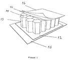
- FIG. 1 shows a composite panel according to the present invention.
- the composite panel comprises two sheets 11,12 of aluminium or aluminium alloy affixed to opposite sides of a core 13.
- the sheets 11,12 may for example have a thickness of 1 mm.
- the core 13 is made from impregnated paper and has a cellular form or a so-called honeycomb structure; that is an integral assembly of pipes preferably having a six-sided cross-section.
- the cells in the core 13 are filled with a heat resistant material 14 preferably consisting of porous particles having a grain size between 0.1 and 1 mm, or with mineral or ceramic fibres. With heat resistant material it shall be understood a material which can resist a fire in Class B 30 or better.
- a preferred material is expanded perlite which can be produced by burning perlite, which is a volcanic mineral, at high temperatures of about 900° C, whereby water is released.
- Perlite may contain 65 - 80 % by weight of SiO 2 and 12 - 16 % by weight of Al 2 O 3 and has a density between 35 and 200 kg/m 2 .
- the core 13 is affixed to the sheets 11,12 by means of a layer of glue which can be applied in the form of a foil and activated by means of heat or radiation.
- glue can be applied as a liquid such as for example a one or two component polyurethane glue.
- a heat resistant glass fibre cloth 16 To the outside of at least one of the sheets 11, 12 of aluminium or aluminium alloy there is affixed a heat resistant glass fibre cloth 16.
- the glass fibre cloth 16 is affixed to the sheets 11, 12 by means of a glue layer which can be applied in the form of a foil or which can be an integral part of the glass fibre cloth.
- the layer of glue can be activated by means of heat or radiation.
- the glue can be applied as a liquid such as for example a one or two component polyurethane glue.
- a glass fibre cloth As high temperature heat resistant glass fibre cloth it is preferred to use a glass fibre cloth as disclosed in Norwegian Patent application No. 820919.
- This glass fibre cloth has one or more polymer-based coatings to which there has been added flame retarding agents.
- Suitable polymers comprises chloride-containing polymers such as polyvinyl chloride, polyvinyl chloride acetate copolymer, acrylic vinyl chloride latex or ethylene chlordane chloride polymers.
- the polymer can be polychloride propene (Neopren), chloride sulfonate polyethers or silicone rubber.
- the flame retarding agents are preferably antimony pentoxide and/or antimony trioxide with aluminium trihydrate as a filler.
- FIG 2 there is shown a cross-section through two composite panels 17, 18 which are joined together.
- the aluminium or aluminium alloy sheets 11, 12 are bended to form channels or grooves 19, 20 of substantially rectangular cross-section at the edge of the composite panels.
- the sheets 11, 12 have on their outer sides a glass fibre cloth 16.
- the grooves 19, 20 are extending into the core 13 in such a way that the grooves in adjacent composite panels are facing each other. In this way the core 13 continue from one composite panel to the next one without any formation of heat bridges in the area of the joint between the composite panels.
- connecting members 21, 22 in such a way that the parts of the sheets 11, 12 which forms the grooves, are pressing against the connecting members21, 22. In this way the edges of the composite panels 17, 18 are connected by a sealed joint which prevents penetration of dust or the like.
- the cores 13 in each of the composite panels 17, 18 will be in contact with each other when the two composite panels are joined together.
- the connecting members 21, 22 are preferably in the form of open profiles made from aluminium or steel and are preferably filled with a heat resistant mineral or ceramic fibre material or with a heat resistant particulate material.
- FIG 3 there is shown two composite panels 23 and 24 connected to each other at an angle of 90°.
- the composite panel 23 is identical to the composite panels shown in figure 2.
- the sheet 11 is bended to form two grooves 25, 26, which grooves have their openings on the side of the composite panel 24 facing the composite panel 23, one outer groove 25 and one inner groove 26 located at a distance from the edge of the composite panel 24, said distance corresponding to the thickness of the composite panel.
- the composite panels 23, 24 have on their outer sides affixed a glass fibre cloth 16.
- the two composite panels 23, 24 are joined together by means of connecting members 27, 28 inserted into the grooves . It will be seen that for both kind of connections of the composite panels shown in figures 3 and 4 the connecting members are separated by the core 13. This will ensure a safe connection which will prevent heat penetration when the joint is exposed to fire.
- FIG 4 there is shown an arc-shaped panel 30 for connection of two composite panels according to the present invention.
- the arc-shaped panel 30 comprises two outer sheets 11, 12 of aluminium or aluminium alloy having affixed on their other side a glass fibre cloth 16.
- the arc-shaped panel 30 has a core 35 which may be identical to the core 13 described above.
- the arc-shaped panel 30 has on its end sides rectangular grooves 32, 33 formed by bending the aluminium or aluminium sheets 11, 12.
- the arc-shaped panel 30 is connected to the composite panels by means of connecting members as described above.
- the composite panels according to the present invention are joined together by inserting connection members into the grooves in one composite panel whereafter another composite panel is placed adjacent the first composite panel and then forced against the connection members until the connection members are pressed into the grooves in the second composite panel. Thereafter any empty spaces in the joint is filled with a particulate or fibre material. For most uses the joint between the composite panels will be tight and smooth and does not need any aftertreatment.
- one or both of the connecting members are permanently affixed in the grooves of one composite panel whereby the connecting members will extend out from the end of the composite panel.
- the composite panel of the present invention is primarily used for walls in different kinds of living quarters and rooms for technical installations on shore, on ships and on offshore structures. Further the composite panels can be used for floors and ceilings. A noise resistance test has shown that for a composite panel having a thickness of 34 mm the noise level was reduced by 34 dB across the composite panel.
- the composite panels according to the present invention have further a substantially lower weight than conventional fire resistant panels.
- test panels In order to test the fire resistance of the composite panels according to the present invention, two composite panels joined together as shown in figure 2 were tested in a gas-fired test furnace.
- the test furnace had inner dimensions of 1m x 1 m x 1m.
- the heating of the test furnace was done according to a time/temperature curve as set out in IMO res A. 754.
- the test panels consisted of two panels according to the present invention, each panel being 1200 mm long and 600 mm wide and connected by a joint using connecting members made from aluminium profiles filled with mineral wool fibres.
- the panels where according to the embodiment shown in figures 1 and 2.
- the honeycomb core was made form paper and had a thickness of 33 mm.
- the cells of the core were filled with expanded perlite having a particle size of 0 - 1 mm.
- the glue was Casco Nobel, type Polyurethane, two-component, 1805 with hardener No. 1802.
- test panels was placed in the open front of the test furnace as shown in figure 5.
- the test lasted for 30 minutes.
- figure 6 there is shown the average temperature and the maximum temperature on the non-exposed side of the test panels during the test period.
- the temperature on the non-exposed side of the test panels was measured by seven thermocouples. The positions of the thermocouples are shown in figure 7.
- the highest average temperature during the test was 140 °C at the end of the test, while the highest maximum temperature was 225 °C.
- the maximum temperature was measured with one of the thermocouples placed in the joint between the two test panels. No penetration of hot gases or flames were observed during the test. The only observation made was a small leakage of smoke in part of the joint between the two panels.
- the test showed that the composite panels according to the present invention have a very high resistance against fire and fulfils the requirements to fire resistance for such panels for the use in ships and on offshore structures.
Landscapes
- Engineering & Computer Science (AREA)
- Architecture (AREA)
- Civil Engineering (AREA)
- Structural Engineering (AREA)
- Physics & Mathematics (AREA)
- Electromagnetism (AREA)
- Building Environments (AREA)
- Laminated Bodies (AREA)
Claims (11)
- Hitzebeständige Verbundplatte enthaltend einen Kern (13) mit einer zellenartigen Struktur aus einem nicht-metallischen Material, wobei die Zellen des Kerns (13) mit einem partikelförmigen mineralischen Material oder mit einem mineralischen oder keramischen Fasermaterial (14) gefüllt sind und wobei die Verbundplatte ferner Bleche (11,12) aus Aluminium oder einer Aluminiumlegierung aufweist, die an jeder Seite des Kerns (13) befestigt sind,
dadurch gekennzeichnet, daß die Verbundplatte ferner ein hochtemperaturbeständiges Glasfasertuch (16) enthält, das an der Außenseite wenigstens eines der Bleche (11,12) aus Aluminium oder Aluminiumlegierung befestigt ist. - Hitzebeständige Verbundplatte nach Anspruch 1,
dadurch gekennzeichnet, daß wenigstens ein Ende der Verbundplatte an der Innenseite der Bleche aus Aluminium oder Aluminiumlegierung (11,12) Mittel zum gegenseitigen Verbinden zweiter Verbundplatten aufweist, wobei die Mittel im wesentlichen rechtwinklige Nuten (19,20) enthalten, wobei die Nuten (19,20) in einer Verbundplatte entsprechenden Nuten in einer zweiten Verbundplatte gegenüberliegen, wenn zwei Verbundplatten einander zugewandt sind, und wobei die Nuten (19,20) dazu vorgesehen sind, Verbindungselemente (21,22) aufzunehmen. - Hitzebeständige Verbundplatte nach Anspruch 1 oder 2,
dadurch gekennzeichnet, daß die zellenartige Struktur des Kerns (13) aus imprägniertem Papier besteht. - Hitzebeständige Verbundplatte nach Anspruch 3,
dadurch gekennzeichnet, daß die Dicke des Kerns (13) zwischen 10 und 200 mm liegt. - Hitzebeständige Verbundplatte nach Anspruch 1 bis 4,
dadurch gekennzeichnet, daß der Kern (13) einen Zellendurchmesser zwischen 5 und 15 mm hat. - Hitzebeständige Verbundplatte nach Anspruch 1 bis 5,
dadurch gekennzeichnet, daß expandiertes Perlit als partikelförmiges mineralisches Material in den Zellen des Kerns (13) verwendet wird. - Hitzebeständige Verbundplatte nach Anspruch 1,
dadurch gekennzeichnet, daß die Bleche aus Aluminium oder Aluminiumlegierung (11, 12) eine Dicke von wenigstens 0,7 mm haben, - Hitzebeständige Verbundplatte nach Anspruch 1,
dadurch gekennzeichnet, daß das Glasfasertuch (16) eine oder mehrere Schichten aus einem Polymer-basiertern Material aufweist, dem ein brandverzögerndes Mittel hinzugefügt ist. - Hitzebeständige Verbundplatte nach Anspruch 2,
dadurch gekennzeichnet, daß die Nuten (19,20) durch Biegen der Bleche aus Aluminium oder Aluminiumlegierung (11,12) geformt sind. - Hitzebeständige Verbundplatte nach Anspruch 2,
dadurch gekennzeichnet, daß zu einer senkrecht zueinander liegenden Verbindung zweier Verbundplatten eine Verbundplatte Nuten (25,26) hat, die an einer der langen Seiten der Verbundplatte angeordnet sind. - Hitzebeständige Verbundplatte nach Anspruch 2,
dadurch gekennzeichnet, daß die Verbindungselemente (21,22) die Form von Hohlprofilen aus Stahl oder Aluminium haben, wobei der Hohlraum mit einem mineralischen oder keramischen Fasermaterial gefüllt ist.
Applications Claiming Priority (3)
| Application Number | Priority Date | Filing Date | Title |
|---|---|---|---|
| NO975108A NO975108A (no) | 1997-11-06 | 1997-11-06 | Varmemotstandsdyktige paneler |
| NO975108 | 1997-11-06 | ||
| PCT/NO1998/000331 WO1999024682A1 (en) | 1997-11-06 | 1998-11-04 | Heat resistant composite panels |
Publications (2)
| Publication Number | Publication Date |
|---|---|
| EP1038075A1 EP1038075A1 (de) | 2000-09-27 |
| EP1038075B1 true EP1038075B1 (de) | 2004-09-15 |
Family
ID=19901299
Family Applications (1)
| Application Number | Title | Priority Date | Filing Date |
|---|---|---|---|
| EP98958412A Expired - Lifetime EP1038075B1 (de) | 1997-11-06 | 1998-11-04 | Hitzebeständige verbundplatte |
Country Status (5)
| Country | Link |
|---|---|
| EP (1) | EP1038075B1 (de) |
| AU (1) | AU1447099A (de) |
| DE (1) | DE69826316D1 (de) |
| NO (1) | NO975108A (de) |
| WO (1) | WO1999024682A1 (de) |
Families Citing this family (14)
| Publication number | Priority date | Publication date | Assignee | Title |
|---|---|---|---|---|
| DE60017043D1 (de) * | 1999-10-07 | 2005-02-03 | Impresa Marinoni S R L | Feuer- und gasdichte Schottdurchführung |
| GR1003563B (el) * | 2000-06-01 | 2001-03-22 | Caretta Interiors �.�. | Συστημα πυρανθεκτικων και ηχομονωτικων πετασματων για επενδυση εσωτερικων χωρων πλοιων |
| US6992027B1 (en) | 2000-11-13 | 2006-01-31 | Hexcel Composites Ltd | Composite panel with fire resistant face sheets |
| AU2001216574A1 (en) * | 2000-11-13 | 2002-05-21 | Hexcel Corporation | Composite panel with fire resistant face sheets |
| JP3505588B2 (ja) * | 2001-02-01 | 2004-03-08 | 独立行政法人交通安全環境研究所 | 軌道用吸音構造 |
| FR2854419A1 (fr) * | 2003-04-29 | 2004-11-05 | Jean Philippe Pisano | Panneau sandwich a ame isolante comportant une structure en nid d'abeilles |
| FR2876720B1 (fr) * | 2004-10-14 | 2007-03-16 | Jean Philippe Pisano | Panneau composite leger rassemblant des qualites d'isolation thermique et phonique |
| WO2009125045A1 (en) * | 2008-04-08 | 2009-10-15 | Joptek Oy Composites | Floor construction |
| WO2010094496A1 (de) * | 2009-02-21 | 2010-08-26 | Herbert Gundelsheimer | Verfahren und system zur kontinuierlichen fertigung von sandwichmaterial |
| ITMI20111007A1 (it) * | 2011-06-01 | 2012-12-02 | Silcart S R L | Pannello multistrato di impermeabilizzazione |
| DE102013111275A1 (de) * | 2013-10-11 | 2015-04-16 | Thyssenkrupp Ag | Bauelement |
| CN108678240B (zh) * | 2018-06-21 | 2019-09-13 | 上海语翀金属制品有限公司 | 一种铝单板的制造工艺 |
| CN111179896B (zh) * | 2020-01-06 | 2022-06-14 | 苏州大学 | 一种蜂窝内嵌耦合结构复合材料及制备方法 |
| CN119239074A (zh) * | 2024-09-30 | 2025-01-03 | 河南科技大学 | 一种铝基复合材料及其制备方法 |
Citations (4)
| Publication number | Priority date | Publication date | Assignee | Title |
|---|---|---|---|---|
| US3998023A (en) * | 1975-08-04 | 1976-12-21 | H. H. Robertson Company | Double-skin insulated building panel |
| US4299872A (en) * | 1977-09-16 | 1981-11-10 | The United States Of America As Represented By The Secretary Of The Navy | Intumescent material-honeycomb thermal barrier |
| US4526830A (en) * | 1980-07-23 | 1985-07-02 | Daniel Ferziger | Coated fabric and mattress ticking |
| US5022208A (en) * | 1988-09-19 | 1991-06-11 | Swiss Aluminium Ltd. | Butt joints for panels and/or sections |
Family Cites Families (5)
| Publication number | Priority date | Publication date | Assignee | Title |
|---|---|---|---|---|
| SE225374C1 (de) * | 1969-03-11 | |||
| WO1984004727A1 (en) * | 1983-05-27 | 1984-12-06 | Boeing Co | Lightweight, fire-retardant structural panel |
| US4598007A (en) * | 1985-02-28 | 1986-07-01 | The United States Of America As Represented By The Administrator Of The National Aeronautics And Space Administration | Light weight fire resistant graphite composites |
| EP0552573B1 (de) * | 1992-01-22 | 2000-05-17 | Isover Saint-Gobain | Feuerfeste Mineralfaserplatte |
| CA2094367A1 (en) * | 1992-04-22 | 1993-10-23 | Michael Windsor Symons | Composite panel |
-
1997
- 1997-11-06 NO NO975108A patent/NO975108A/no unknown
-
1998
- 1998-11-04 DE DE69826316T patent/DE69826316D1/de not_active Expired - Lifetime
- 1998-11-04 EP EP98958412A patent/EP1038075B1/de not_active Expired - Lifetime
- 1998-11-04 WO PCT/NO1998/000331 patent/WO1999024682A1/en not_active Ceased
- 1998-11-04 AU AU14470/99A patent/AU1447099A/en not_active Abandoned
Patent Citations (4)
| Publication number | Priority date | Publication date | Assignee | Title |
|---|---|---|---|---|
| US3998023A (en) * | 1975-08-04 | 1976-12-21 | H. H. Robertson Company | Double-skin insulated building panel |
| US4299872A (en) * | 1977-09-16 | 1981-11-10 | The United States Of America As Represented By The Secretary Of The Navy | Intumescent material-honeycomb thermal barrier |
| US4526830A (en) * | 1980-07-23 | 1985-07-02 | Daniel Ferziger | Coated fabric and mattress ticking |
| US5022208A (en) * | 1988-09-19 | 1991-06-11 | Swiss Aluminium Ltd. | Butt joints for panels and/or sections |
Also Published As
| Publication number | Publication date |
|---|---|
| AU1447099A (en) | 1999-05-31 |
| WO1999024682A1 (en) | 1999-05-20 |
| DE69826316D1 (de) | 2004-10-21 |
| NO304442B1 (no) | 1998-12-14 |
| NO975108A (no) | 1998-12-14 |
| EP1038075A1 (de) | 2000-09-27 |
| NO975108D0 (no) | 1997-11-06 |
Similar Documents
| Publication | Publication Date | Title |
|---|---|---|
| EP1038075B1 (de) | Hitzebeständige verbundplatte | |
| US4467577A (en) | Intumescent fire barrier material laminated with restraining layer | |
| CA1166816A (en) | Building element | |
| US7018699B2 (en) | Fire stop article | |
| US4747247A (en) | Roof system | |
| JP7402212B2 (ja) | 建築パネル | |
| KR100850965B1 (ko) | 단열접착제 조성물 및 이를 이용한 단열재 | |
| JP2008184896A (ja) | 耐火性部材と、その施工方法 | |
| CA2617021C (en) | Composite insulated building panel | |
| KR20200143223A (ko) | 건축용 복합 단열판재 | |
| CA1168969A (en) | Intumescent fire barrier material laminated with restraining layer | |
| JP5283490B2 (ja) | 目地材 | |
| KR102809364B1 (ko) | 내화 발포 시트 및 이를 이용한 샌드위치 패널 | |
| CN213143589U (zh) | 一种用于换流变阀厅的封堵板材 | |
| CN223048238U (zh) | 一种装配式防火墙材 | |
| CN210501695U (zh) | 耐腐蚀防火h型钢板 | |
| CN217463530U (zh) | 一种复合板制成的耐高温复合型风管 | |
| CN223116002U (zh) | 一种叠层气凝胶复合板材 | |
| EP4706953A1 (de) | Schichtaufbau einer flachen, formstabilen bauplatte und aus dem schichtaufbau hergestellter selbsttragender luftkanal | |
| JP2021008712A (ja) | 断熱パネルで構成された壁の耐火被覆構造、および断熱パネル耐火用被覆体 | |
| WO2005003479A2 (en) | Improvements to building components | |
| CN217400090U (zh) | 一种低碳节能建筑墙板 | |
| JPH1136473A (ja) | 断熱耐火シート | |
| KR200496605Y1 (ko) | 건축용 합지보드 | |
| JPS6035698Y2 (ja) | 耐火断熱性建築用板 |
Legal Events
| Date | Code | Title | Description |
|---|---|---|---|
| PUAI | Public reference made under article 153(3) epc to a published international application that has entered the european phase |
Free format text: ORIGINAL CODE: 0009012 |
|
| 17P | Request for examination filed |
Effective date: 20000606 |
|
| AK | Designated contracting states |
Kind code of ref document: A1 Designated state(s): DE DK ES FI FR GB IE IT |
|
| 17Q | First examination report despatched |
Effective date: 20030129 |
|
| GRAP | Despatch of communication of intention to grant a patent |
Free format text: ORIGINAL CODE: EPIDOSNIGR1 |
|
| GRAS | Grant fee paid |
Free format text: ORIGINAL CODE: EPIDOSNIGR3 |
|
| GRAA | (expected) grant |
Free format text: ORIGINAL CODE: 0009210 |
|
| AK | Designated contracting states |
Kind code of ref document: B1 Designated state(s): DE DK ES FI FR GB IE IT |
|
| PG25 | Lapsed in a contracting state [announced via postgrant information from national office to epo] |
Ref country code: IT Free format text: LAPSE BECAUSE OF FAILURE TO SUBMIT A TRANSLATION OF THE DESCRIPTION OR TO PAY THE FEE WITHIN THE PRESCRIBED TIME-LIMIT;WARNING: LAPSES OF ITALIAN PATENTS WITH EFFECTIVE DATE BEFORE 2007 MAY HAVE OCCURRED AT ANY TIME BEFORE 2007. THE CORRECT EFFECTIVE DATE MAY BE DIFFERENT FROM THE ONE RECORDED. Effective date: 20040915 Ref country code: FR Free format text: LAPSE BECAUSE OF FAILURE TO SUBMIT A TRANSLATION OF THE DESCRIPTION OR TO PAY THE FEE WITHIN THE PRESCRIBED TIME-LIMIT Effective date: 20040915 Ref country code: FI Free format text: LAPSE BECAUSE OF FAILURE TO SUBMIT A TRANSLATION OF THE DESCRIPTION OR TO PAY THE FEE WITHIN THE PRESCRIBED TIME-LIMIT Effective date: 20040915 |
|
| REG | Reference to a national code |
Ref country code: GB Ref legal event code: FG4D |
|
| REG | Reference to a national code |
Ref country code: IE Ref legal event code: FG4D |
|
| REF | Corresponds to: |
Ref document number: 69826316 Country of ref document: DE Date of ref document: 20041021 Kind code of ref document: P |
|
| PG25 | Lapsed in a contracting state [announced via postgrant information from national office to epo] |
Ref country code: IE Free format text: LAPSE BECAUSE OF NON-PAYMENT OF DUE FEES Effective date: 20041104 |
|
| PG25 | Lapsed in a contracting state [announced via postgrant information from national office to epo] |
Ref country code: GB Free format text: LAPSE BECAUSE OF NON-PAYMENT OF DUE FEES Effective date: 20041215 Ref country code: DK Free format text: LAPSE BECAUSE OF FAILURE TO SUBMIT A TRANSLATION OF THE DESCRIPTION OR TO PAY THE FEE WITHIN THE PRESCRIBED TIME-LIMIT Effective date: 20041215 |
|
| PG25 | Lapsed in a contracting state [announced via postgrant information from national office to epo] |
Ref country code: DE Free format text: LAPSE BECAUSE OF FAILURE TO SUBMIT A TRANSLATION OF THE DESCRIPTION OR TO PAY THE FEE WITHIN THE PRESCRIBED TIME-LIMIT Effective date: 20041216 |
|
| PG25 | Lapsed in a contracting state [announced via postgrant information from national office to epo] |
Ref country code: ES Free format text: LAPSE BECAUSE OF FAILURE TO SUBMIT A TRANSLATION OF THE DESCRIPTION OR TO PAY THE FEE WITHIN THE PRESCRIBED TIME-LIMIT Effective date: 20041226 |
|
| PLBE | No opposition filed within time limit |
Free format text: ORIGINAL CODE: 0009261 |
|
| STAA | Information on the status of an ep patent application or granted ep patent |
Free format text: STATUS: NO OPPOSITION FILED WITHIN TIME LIMIT |
|
| GBPC | Gb: european patent ceased through non-payment of renewal fee |
Effective date: 20041215 |
|
| REG | Reference to a national code |
Ref country code: IE Ref legal event code: MM4A |
|
| 26N | No opposition filed |
Effective date: 20050616 |
|
| EN | Fr: translation not filed |