EP1038481A2 - Kleiderbügel - Google Patents
Kleiderbügel Download PDFInfo
- Publication number
- EP1038481A2 EP1038481A2 EP00103225A EP00103225A EP1038481A2 EP 1038481 A2 EP1038481 A2 EP 1038481A2 EP 00103225 A EP00103225 A EP 00103225A EP 00103225 A EP00103225 A EP 00103225A EP 1038481 A2 EP1038481 A2 EP 1038481A2
- Authority
- EP
- European Patent Office
- Prior art keywords
- deflector
- bracket
- clothes hanger
- hanger according
- legs
- Prior art date
- Legal status (The legal status is an assumption and is not a legal conclusion. Google has not performed a legal analysis and makes no representation as to the accuracy of the status listed.)
- Withdrawn
Links
- 239000000725 suspension Substances 0.000 claims description 6
- 229920003023 plastic Polymers 0.000 abstract description 3
- 230000000903 blocking effect Effects 0.000 abstract 1
- 239000002184 metal Substances 0.000 description 2
- 230000026058 directional locomotion Effects 0.000 description 1
- 229920002457 flexible plastic Polymers 0.000 description 1
- 230000033001 locomotion Effects 0.000 description 1
- 238000000034 method Methods 0.000 description 1
- 230000035515 penetration Effects 0.000 description 1
- 230000002787 reinforcement Effects 0.000 description 1
- 239000011435 rock Substances 0.000 description 1
Images


Classifications
-
- A—HUMAN NECESSITIES
- A47—FURNITURE; DOMESTIC ARTICLES OR APPLIANCES; COFFEE MILLS; SPICE MILLS; SUCTION CLEANERS IN GENERAL
- A47G—HOUSEHOLD OR TABLE EQUIPMENT
- A47G25/00—Household implements used in connection with wearing apparel; Dress, hat or umbrella holders
- A47G25/14—Clothing hangers, e.g. suit hangers
- A47G25/48—Hangers with clamps or the like, e.g. for trousers or skirts
- A47G25/483—Hangers with clamps or the like, e.g. for trousers or skirts with pivoting clamps or clips having axis of rotation parallel with the hanger arms
- A47G25/485—Hangers with clamps or the like, e.g. for trousers or skirts with pivoting clamps or clips having axis of rotation parallel with the hanger arms with a plurality of clips integral with, or supported by, the trouser-supporting bar
-
- A—HUMAN NECESSITIES
- A47—FURNITURE; DOMESTIC ARTICLES OR APPLIANCES; COFFEE MILLS; SPICE MILLS; SUCTION CLEANERS IN GENERAL
- A47G—HOUSEHOLD OR TABLE EQUIPMENT
- A47G25/00—Household implements used in connection with wearing apparel; Dress, hat or umbrella holders
- A47G25/14—Clothing hangers, e.g. suit hangers
- A47G25/48—Hangers with clamps or the like, e.g. for trousers or skirts
- A47G25/483—Hangers with clamps or the like, e.g. for trousers or skirts with pivoting clamps or clips having axis of rotation parallel with the hanger arms
- A47G2025/484—Hangers for trousers or skirts with clamps comprising protection means against inadvertent opening
Definitions
- the invention relates to a hanger with a Temple body, in the middle area an upwards protruding hanging hook is arranged and the two pointing to opposite sides of the suspension hook Forms arm arms, on each of which at least one bracket is arranged, the two pivotable on the bracket body has bracketed legs attached to the in her arranged lower jaws by means of a Are tensioned against each other and in their upper Area each have an actuating section.
- Such a hanger is usually called a clip hanger designated and is e.g. in EP 0 656 185 shown. It serves items of clothing such as skirts, pants etc. in a hanging position for transport, storage and keep the presentation safe.
- the hanger consists mainly of plastic, only the Suspension hook and the spring designed as a metal part are.
- Each clip consists of two clip legs that point to arranged and on different sides of the bracket body this are pivotally mounted. Every clip leg has a jaw located under the temple body and one arranged above the bracket body Actuating section, the clamp legs by means of the spring are clamped against each other on the jaws.
- the user opens to clip on a piece of clothing the clamp by holding the two clamp legs their operating sections located at the upper ends presses against the force of the spring, whereby the staple legs pivot relative to each other and a space between their lower jaws form, into which the garment to be hung can be inserted is. After releasing the clamp legs, the Jaws moved towards each other due to the spring force and clamp the garment between them.
- the invention has for its object a hanger to create the type mentioned, in which a jamming of clips with other hangers in conveyor and Sorting systems is reliably avoided.
- the deflector elements arranged on the bracket body on both sides of the bracket Deflector plates are formed.
- the deflector plates are not part of the bracket, but attached to the bracket body, so that the constructive Structure of the actual bracket does not change.
- the deflector plates on the top to form the bracket body so that they are essentially vertically upwards and perpendicular to the temple level extend.
- the deflector plates form together with the clasp legs a circumferential, outside in essentially closed housing in which long objects, such as someone else’s temple body Hangers, can not penetrate.
- the deflector plates have a width at their upper edges that larger than the distance between the inside of the Upper edges of the clamp legs and smaller than that Distance between the outsides of the tops of the Brace leg is. In this way it can be achieved that the deflector plates are not in the transverse direction of the Protruding from the clip and on the other hand is between the inner surfaces of the staple legs and the deflector plates have not formed a gap in the one Component of another hanger can penetrate.
- the deflector elements from on the top the flexible limb attached to the clamp leg are formed, which are directed towards each other.
- the Deflector lips are thus directly in the gap between the operating sections of the staple legs and at least partially shield it from the outside.
- the deflector lips preferably abut one another, so that the space between the operating sections the bracket leg is completely covered.
- the operating portions of the Bracket legs are moved towards each other flexible deflector lips elastically deformed so that the Opening movement is not hindered. After closing the The deflector lips sweep clamp due to their elasticity back to their starting position.
- the deflector lips can essentially be directly on top of each other to be directed and thus run horizontally, however, it is preferably provided that the deflector lips slanting from the top edge of the staple legs extend upwards. In this way, on the one hand achieved that the deflector lips when opening the Let the bracket deform slightly, on the other hand guide the Deflector lips an adjacent, approaching from above Hangers due to their roof-like configuration sideways, so that jamming reliably avoided is.
- the deflector lips can be made of a flexible plastic consist and for example also on the Plastic existing clamp legs in a two-component process be sprayed on.
- the deflector elements from in the upper area the clamp leg arranged, one on top of the other are formed into directional deflector fingers that are offset to each other that when you press the Run the bracket past each other. It is preferable a deflector finger on each side of each clamp leg arranged in this way at least in the upper area the bracket has a substantially closed to get all-round frame.
- the top edges of the deflector fingers should be on the same Height with the upper edges of the clamp legs.
- bracket leg of a bracket should be something longer than half the distance between the clamp legs in the be the upper area so that the facing each other Deflector finger in the unactuated state of the clamp around slightly overlapping. Even in this condition thus penetration of another hanger into the Clearance between the operating sections one Brackets difficult or prevented.
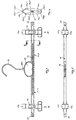
- a hanger 10 shown in FIGS. 1 to 3 has a rod-shaped elongated, horizontally arranged bracket body 11 on the one in its midsection on top a molded-on middle part 13 with a Has reinforcement 13a in which an extending upward Suspension hook 12 is set.
- the temple body 11 forms two on opposite sides of the Suspension hook 12 pointing bracket arms 11.1 and 11.2 in their outer end areas with one after each outside facing rock hooks 20 are provided.
- everybody Arm 11.1 and 11.2 carries a bracket 15 with which Garment can be clamped.
- the bracket body 11 has an I-shaped Cross section with an additional middle bracing Rib.
- On a top flange 11a of the bracket body 11 is a clip leg 15a or 15b of the clip 15 with an inner central support section 15a3 or 15b3.
- the clamp legs 15a and 15b are made of metal U-shaped spring 14 in its on the top chord 11a held in position and point in their an actuating section 15a1 or 15b1 as well as one in their lower area Clamping jaws 15a2 or 15b2.
- the jaws 15a2 and 15b2 are biased by the spring 14 so that they rest against each other under the force of the spring 14.
- bracket 15 At the upper end of the bracket 15 have the operating sections 15a1 and 15b1 of the clamp legs 15a and 15b a mutual distance that allows the two clamp legs 15a and 15b for opening the Bracket 15 at its operating portions 15a1 and 15b1 compress against the force of the spring 14, whereby the clamp legs 15a and 15b relative to each other swivel around their support axis sections 15a3 and 15b3 and one between their lower jaws 15a2 and 15b2 Form a gap in the garment to be hung can be introduced. After releasing the staple legs 15a and 15b are the jaws 15a2 and 15b2 as a result the spring force moves towards each other again and clamp the garment firmly between them.
- each bracket 15 Deflector plate 16a and 16b arranged on the Top of the bracket body 11 is formed and itself extends vertically upwards and perpendicular to the temple level. The distance between the two deflector plates 16a and 16b corresponds to the width of the bracket 15, so that the deflector plates 16a and 16b the clamp legs 15a and 15b between them tightly.
- FIG. 3 shows the width of the deflector plates 16a and 16b starting from the bracket body 11 upwards steadily increasing, with the deflector plates in all cross sections have a width greater than the distance between the inner sides of the clamp legs 15a and 15b and less than the distance between the outside of the Bracket legs 15a and 15b is so that the deflector plates 16a and 16b not laterally over the clamp legs 15a and 15b protrude, however, the sides of the between completely cover this formed space.
- the height of the deflector plates 16a and 16b is such that their upper edges 16a1 and 16b1 with the upper edges of the Bracket legs 15a and 15b are at one height. On this prevents a bracket body from a another hanger from above into the space between can penetrate the clamp legs of a clamp, if several hangers side by side on a clothes rail or a transport device of an automatic Sorting and conveyor system hang.
- Figures 4 to 6 show a second embodiment of a hanger 10, which with the first exemplary embodiment agrees in essential points and differs from this only in that flexible deflector lips instead of deflector plates 17a and 17b are provided on the top of the Bracket legs 15a and 15b are attached and starting of these run towards each other at an angle so that with their free edges 17a1 and 17b1 issue.
- the deflector lips 17a and 17b extend over the entire width of the clamp legs 15a and 15b and thus cover the upper one formed between them Gap in roof-like configuration ( Figure 6). When the clamp is operated or opened, the deflector lips become 17a and 17b elastically deformed, but sweep after releasing the clip back into its original position back.
- FIGS 7 to 9 show a third embodiment, this also in the basic structure of the former Embodiment corresponds and from this differs in that instead of the deflector plates now attached in the upper area of the clamp legs, deflector fingers 18a directed towards one another, 18b, 19a, 19b are provided.
- deflector fingers 18a directed towards one another, 18b, 19a, 19b are provided on each side of each Bracket legs 15a and 15b.
- the deflector fingers in the longitudinal direction of the bracket body are offset from each other that they run close together when the clamp 15 is actuated.
- the length of the deflector fingers 18a, 18b, 19a and 19b is dimensioned so that the deflector fingers in unactuated state of the bracket 15 to a small extent overlap, their upper edges 18b1, 19a1 being on the same Height with the upper edges of the clamp legs 15a and 15b lie.
- the deflector fingers are on opposite sides outside the Bracket legs molded.
- the deflector fingers can also be used in the middle area of the Actuating sections of the clamp legs are formed be and then also when the clamp is pressed together walk past.
Landscapes
- Holders For Apparel And Elements Relating To Apparel (AREA)
- Pharmaceuticals Containing Other Organic And Inorganic Compounds (AREA)
- Chain Conveyers (AREA)
Abstract
Description
- Figur 1
- eine Seitenansicht eines Kleiderbügels gemäß einem ersten Ausführungsbeispiel,
- Figur 2
- eine Aufsicht auf den Kleiderbügel gemäß Figur 1,
- Figur 3
- den Schnitt III-III in Figur 1,
- Figur 4
- eine Seitenansicht eines Kleiderbügels gemäß einem zweiten Ausführungsbeispiel,
- Figur 5
- eine Aufsicht auf den Kleiderbügel gemäß Figur 4,
- Figur 6
- den Schnitt VI-VI in Figur 4,
- Figur 7
- eine Seitenansicht eines Kleiderbügels gemäß einem dritten Ausführungsbeispiels,
- Figur 8
- eine Aufsicht auf den Kleiderbügel gemäß Figur 7 und
- Figur 9
- den Schnitt IX-IX in Figur 7.
Claims (13)
- Kleiderbügel mit einem Bügelkörper (11), in dessen mittlerem Bereich ein nach oben hervorstehender Aufhängehaken (12) angeordnet ist und der zwei zu entgegengesetzten Seiten des Aufhängehakens (12) weisende Bügelarme (11.1, 11.2) bildet, auf denen jeweils zumindest eine Klammer (15) angeordnet ist, die zwei schwenkbar am Bügelkörper (11) gelagerte Klammerschenkel (15a, 15b) aufweist, die an in ihrem unteren Bereich angeordneten Klemmbacken (15a2, 15b2) mittels einer Feder (14) gegeneinander gespannt sind und in ihrem oberen Bereich jeweils einen Betätigungsabschnitt (15a1, 15b1) aufweisen, dadurch gekennzeichnet, daß den Betätigungsabschnitten (15a1, 15b1) Abweiserelemente (16a, 16b; 17a, 17b; 18a, 18b, 19a, 19b) zugeordnet sind, die den Zwischenraum zwischen den Betätigungsabschnitten (15a1, 15b1) überbrücken.
- Kleiderbügel nach Anspruch 1, dadurch gekennzeichnet, daß die Abweiserelemente von am Bügelkörper (11) auf beiden Seiten der Klammer (15) angeordneten Abweiserplatten (16a, 16b) gebildet sind.
- Kleiderbügel nach Anspruch 2, dadurch gekennzeichnet, daß die Abweiserplatten (16a, 16b) auf der Oberseite des Bügelkörpers (11) angeformt sind und sich im wesentlichen vertikal nach oben und senkrecht zur Bügelebene erstrecken.
- Kleiderbügel nach Anspruch 2 oder 3, dadurch gekennzeichnet, daß die Abweiserplatten (16a, 16b) die Klammerschenkel (15a, 15b) unter enger Passung zwischen sich aufnehmen.
- Kleiderbügel nach einem der Ansprüche 2 bis 4, dadurch gekennzeichnet, daß die Oberkanten (16a1, 16b1) der Abweiserplatten (16a, 16b) in Höhe der Oberkanten der Klammerschenkel (15a1, 15b1) liegen.
- Kleiderbügel nach einem der Ansprüche 2 bis 5, dadurch gekennzeichnet, daß die Abweiserplatten (16a, 16b) an ihren Oberkanten (16a1, 16b1) eine Breite aufweisen, die größer als der Abstand zwischen den Innenseiten der Oberkanten der Klammerschenkel (15a, 15b) und kleiner als der Abstand zwischen Außenseiten der Oberkanten der Klammerschenkel (15a, 15b) ist.
- Kleiderbügel nach Anspruch 1, dadurch gekennzeichnet, daß die Abweiserelemente von an der Oberseite der Klammerschenkel (15a, 15b) angebrachten, flexiblen Abweiserlippen (17a, 17b) gebildet sind, die aufeinander zugerichtet sind.
- Kleiderbügel nach Anspruch 7, dadurch gekennzeichnet, daß die Abweiserlippen (17a, 17b) aneinander anliegen.
- Kleiderbügel nach Anspruch 7 oder 8, dadurch gekennzeichnet, daß die Abweiserlippen (17a, 17b) sich von der Oberkante der Klammerschenkel (15a, 15b) schräg nach oben erstrecken.
- Kleiderbügel nach Anspruch 1, dadurch gekennzeichnet, daß die Abweiserelemente von im oberen Bereich der Klammerschenkel (15a, 16b) angeordneten, aufeinander zu gerichteten Abweiserfingern (18a, 18b, 19a, 19b) gebildet sind, die derart zueinander versetzt sind, daß sie bei Betätigung der Klammer (15) aneinander vorbeilaufen.
- Kleiderbügel nach Anspruch 10, dadurch gekennzeichnet, daß auf jeder Seite des Klammerschenkels (15a, 15b) ein Abweiserfinger (18a, 18b, 19a, 19b) angeordnet ist.
- Kleiderbügel nach Anspruch 10 oder 11, dadurch gekennzeichnet, daß die Oberkanten der Abweiserfinger (18a, 18b, 19a, 19b) auf gleicher Höhe mit den Oberkanten der Klammerschenkel (15a, 15b) liegen.
- Kleiderbügel nach einem der Ansprüche 10 bis 12, dadurch gekennzeichnet, daß die einander zugewandten Abweiserfinger (18a, 18b, 19a, 19b) sich im unbetätigten Zustand der Klammer (15) um ein geringes Maß überlappen.
Applications Claiming Priority (2)
| Application Number | Priority Date | Filing Date | Title |
|---|---|---|---|
| DE29905270U | 1999-03-23 | ||
| DE29905270U DE29905270U1 (de) | 1999-03-23 | 1999-03-23 | Kleiderbügel |
Publications (2)
| Publication Number | Publication Date |
|---|---|
| EP1038481A2 true EP1038481A2 (de) | 2000-09-27 |
| EP1038481A3 EP1038481A3 (de) | 2003-01-15 |
Family
ID=8071244
Family Applications (1)
| Application Number | Title | Priority Date | Filing Date |
|---|---|---|---|
| EP00103225A Withdrawn EP1038481A3 (de) | 1999-03-23 | 2000-02-17 | Kleiderbügel |
Country Status (2)
| Country | Link |
|---|---|
| EP (1) | EP1038481A3 (de) |
| DE (1) | DE29905270U1 (de) |
Cited By (1)
| Publication number | Priority date | Publication date | Assignee | Title |
|---|---|---|---|---|
| GB2401038B (en) * | 2002-02-15 | 2006-05-17 | Stanley Frederick Gouldson | Improved pinch grip hangers |
Citations (1)
| Publication number | Priority date | Publication date | Assignee | Title |
|---|---|---|---|---|
| EP0656185A2 (de) | 1993-12-03 | 1995-06-07 | Batts, Inc. | Verstellbarer Kleiderbügel |
Family Cites Families (3)
| Publication number | Priority date | Publication date | Assignee | Title |
|---|---|---|---|---|
| US3946915A (en) * | 1974-12-05 | 1976-03-30 | A & E Plastik Pak Co., Inc. | Garment hanger with clamp guard |
| US4009807A (en) * | 1975-12-11 | 1977-03-01 | Red Wing Products Inc. | Garment hanger |
| AU635426B2 (en) * | 1990-06-01 | 1993-03-18 | Spotless Plastics Pty. Ltd. | Improved clip for garment hanger |
-
1999
- 1999-03-23 DE DE29905270U patent/DE29905270U1/de not_active Expired - Lifetime
-
2000
- 2000-02-17 EP EP00103225A patent/EP1038481A3/de not_active Withdrawn
Patent Citations (1)
| Publication number | Priority date | Publication date | Assignee | Title |
|---|---|---|---|---|
| EP0656185A2 (de) | 1993-12-03 | 1995-06-07 | Batts, Inc. | Verstellbarer Kleiderbügel |
Cited By (5)
| Publication number | Priority date | Publication date | Assignee | Title |
|---|---|---|---|---|
| GB2401038B (en) * | 2002-02-15 | 2006-05-17 | Stanley Frederick Gouldson | Improved pinch grip hangers |
| GB2420698A (en) * | 2002-02-15 | 2006-06-07 | Stanley Frederick Gouldson | Elongated pinch grip hanger |
| GB2420698B (en) * | 2002-02-15 | 2006-09-20 | Stanley Frederick Gouldson | Improved pinch grip hangers |
| GB2424829A (en) * | 2002-02-15 | 2006-10-11 | Stanley Frederick Gouldson | Pinch grip garment hanger including an offset mounting portion for magazine feed and automated loading of garments |
| GB2424829B (en) * | 2002-02-15 | 2007-02-28 | Stanley Frederick Gouldson | Improved pinch grip hangers |
Also Published As
| Publication number | Publication date |
|---|---|
| EP1038481A3 (de) | 2003-01-15 |
| DE29905270U1 (de) | 1999-06-24 |
Similar Documents
| Publication | Publication Date | Title |
|---|---|---|
| EP0346780B1 (de) | Rock- oder Hosenspanner | |
| DE69100036T2 (de) | Beschlag fuer einen fensterfluegel eines kippfensters mit verbesserter schliessung. | |
| EP1038481A2 (de) | Kleiderbügel | |
| DE3207307A1 (de) | Vorrichtung zum spannen von zu buegelnden hosen u.dgl. | |
| WO2017072106A1 (de) | Führungsanordnung für schiebetüren und schrankmöbel | |
| DE8800293U1 (de) | Korpus, insbesondere Möbelstück, mit einem Beschlag für eine Tür | |
| AT409880B (de) | Kreuzgelenkscharnier | |
| DE19646053A1 (de) | Aufhängerstütze für Kleiderbeutel | |
| EP0388668A1 (de) | Einhängevorrichtung für einen Hängeförderer | |
| EP0289714A1 (de) | Kleiderbügel | |
| DE9210451U1 (de) | Transportbügel | |
| DE10053626B4 (de) | Kleiderbügel | |
| EP1336363B1 (de) | Kleider- und Wäschebügel | |
| DE202004009513U1 (de) | Bügel für insbesondere Bekleidungsstücke | |
| DE60119617T2 (de) | Kleiderbügel | |
| DE3901870C2 (de) | ||
| DE2949339A1 (de) | Buegelsicherung fuer eine in transportbehaeltern, insbesondere containern, zum transport von kleidungsstuecken parallel zur oeffnungsseite des transportbehaelters | |
| DE4101323A1 (de) | Vorrichtung zum transport von kleidungsstuecken, die auf kleiderbuegeln haengen | |
| DE9301172U1 (de) | Abhängeelement zur Befestigung von Tragschienen für abgehängte Decken | |
| DE29515437U1 (de) | Transportbügel | |
| DE926155C (de) | Rollklammer fuer Gardinen, Vorhaenge od. dgl. | |
| DE20216373U1 (de) | Wäschebügel, insbesondere für String-Tanga | |
| EP0796581A1 (de) | Transportbügel | |
| DE29603274U1 (de) | Wäscheklammer | |
| DE1790777U (de) | Einbaukratzer fuer doppelkettenfoerderer. |
Legal Events
| Date | Code | Title | Description |
|---|---|---|---|
| PUAI | Public reference made under article 153(3) epc to a published international application that has entered the european phase |
Free format text: ORIGINAL CODE: 0009012 |
|
| AK | Designated contracting states |
Kind code of ref document: A2 Designated state(s): AT BE CH CY DE DK ES FI FR GB GR IE IT LI LU MC NL PT SE |
|
| AX | Request for extension of the european patent |
Free format text: AL;LT;LV;MK;RO;SI |
|
| PUAL | Search report despatched |
Free format text: ORIGINAL CODE: 0009013 |
|
| AK | Designated contracting states |
Kind code of ref document: A3 Designated state(s): AT BE CH CY DE DK ES FI FR GB GR IE IT LI LU MC NL PT SE |
|
| AX | Request for extension of the european patent |
Free format text: AL;LT;LV;MK;RO;SI |
|
| AKX | Designation fees paid | ||
| REG | Reference to a national code |
Ref country code: DE Ref legal event code: 8566 |
|
| STAA | Information on the status of an ep patent application or granted ep patent |
Free format text: STATUS: THE APPLICATION IS DEEMED TO BE WITHDRAWN |
|
| 18D | Application deemed to be withdrawn |
Effective date: 20030716 |