EP1038486A2 - Jeu de pièces pour cloisons de douches - Google Patents
Jeu de pièces pour cloisons de douches Download PDFInfo
- Publication number
- EP1038486A2 EP1038486A2 EP00105275A EP00105275A EP1038486A2 EP 1038486 A2 EP1038486 A2 EP 1038486A2 EP 00105275 A EP00105275 A EP 00105275A EP 00105275 A EP00105275 A EP 00105275A EP 1038486 A2 EP1038486 A2 EP 1038486A2
- Authority
- EP
- European Patent Office
- Prior art keywords
- profile
- leg
- profiles
- web
- kit
- Prior art date
- Legal status (The legal status is an assumption and is not a legal conclusion. Google has not performed a legal analysis and makes no representation as to the accuracy of the status listed.)
- Granted
Links
Images



Classifications
-
- A—HUMAN NECESSITIES
- A47—FURNITURE; DOMESTIC ARTICLES OR APPLIANCES; COFFEE MILLS; SPICE MILLS; SUCTION CLEANERS IN GENERAL
- A47K—SANITARY EQUIPMENT; ACCESSORIES THEREFOR, e.g. TOILET ACCESSORIES
- A47K3/00—Baths; Showers; Appurtenances therefor
- A47K3/28—Showers or bathing douches
- A47K3/30—Screens or collapsible cabinets for showers or baths
-
- A—HUMAN NECESSITIES
- A47—FURNITURE; DOMESTIC ARTICLES OR APPLIANCES; COFFEE MILLS; SPICE MILLS; SUCTION CLEANERS IN GENERAL
- A47K—SANITARY EQUIPMENT; ACCESSORIES THEREFOR, e.g. TOILET ACCESSORIES
- A47K3/00—Baths; Showers; Appurtenances therefor
- A47K3/28—Showers or bathing douches
- A47K3/30—Screens or collapsible cabinets for showers or baths
- A47K3/34—Slidable screens
-
- A—HUMAN NECESSITIES
- A47—FURNITURE; DOMESTIC ARTICLES OR APPLIANCES; COFFEE MILLS; SPICE MILLS; SUCTION CLEANERS IN GENERAL
- A47K—SANITARY EQUIPMENT; ACCESSORIES THEREFOR, e.g. TOILET ACCESSORIES
- A47K3/00—Baths; Showers; Appurtenances therefor
- A47K3/28—Showers or bathing douches
- A47K3/30—Screens or collapsible cabinets for showers or baths
- A47K2003/307—Adjustable connections to the wall
Definitions
- the invention relates to a kit for shower enclosures according to the The preamble of claim 1 features specified.
- shower enclosures contain frames made of profiled rails, which are made in particular Aluminum or an aluminum alloy and with suitable fasteners are interconnected.
- shower enclosures can be telescopic sliding doors that can be moved relative to each other, hinged wing doors or folding doors included, with suitable guide means or bearing means being provided, wherein the doors essentially as flat elements or as curved or as required angled elements can be formed.
- shower enclosures can have fixed wall elements which are on the side of a passage opening, which can be closed with the doors mentioned and released if necessary become. Such fixed wall elements can be in the side of the passage opening the same vertical plane as this or at a predeterminable angle to this can be arranged. Due to the variety of types of shower enclosures was previously a correspondingly large number of rails and thus a high manufacturing and Warehousing effort required.
- the invention has for its object a kit of Propose rails, which in different types of shower partition and / or can be provided for different installation options.
- the profile rails hereinafter referred to simply as profiles, should according to the respective conditions of use with each other and if necessary with other profit tracks or profiles can be combined and with a reduced
- the share of profiles and accessories is said to be a large variety of types of shower enclosures can be realized.
- the kit proposed according to the invention comprises a first profile with a approximately U-shaped cross section and a second profile with an approximate L-shaped cross-section, the respective outer legs of these profiles in Area of the visible outer surfaces approximately coincident are.
- the two profiles can be connected to one another with connecting elements for example a corner post with two matching ones visible to a viewer and approximately at right angles to each other outer surfaces receive.
- the first profile contains approximately parallel to the outer leg mentioned an inner leg, said leg with a connecting leg are interconnected.
- the connecting leg are more appropriate Way fasteners in the form of grooves, rear-engaging webs or the like Attachment of another profile assigned.
- the fasteners are also arranged such that the first profile with a wall, be it a fixed room wall a shower or bath room or with a side wall of the shower partition is connectable.
- the second profile contains the one angled from the outer leg Leg a groove for receiving a plate, in particular a fixed wall element. This groove is particularly provided such that the plate approximately runs in the same direction as the outer leg of the second profile.
- the profiles mentioned can be shared with others Profiles are combined, which, for example, articulated body for a door leaf contain or the connection of a fixed wall element in a predetermined Allow angles.
- the outer leg and the inner leg of the first profile are preferably designed and assigned to one another such that a compensation profile at the required depth in the space between the legs can be inserted, a connection body being provided in an expedient manner is to specify the insertion depth in cooperation with a connecting element to be able to.
- the fixed wall elements are for the different types of shower partitions are designed to match, so that the manufacturing and storage costs is further reduced.
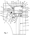
- the two profiles 1, 2 are part of a frame, which According to the drawing, an upper profile rail, not shown here, in front of the drawing level and has a lower profile rail 4 lying behind the plane of the drawing, which is indicated with dash-dotted lines.
- the two rails are used for Suspension and guidance of three sliding doors, only one sliding door 6 is partially shown.
- This sliding door 6 contains a plate 8, in particular made of glass or a transparent plastic, and a handle profile 10 and is suitable slidably suspended in the above horizontal rail.
- Both profiles 1, 2 are in the corner area of a shower tray which is only partially shown here 12 arranged and substantially perpendicular to the sliding door 6 is a fixed Wall element 14 is provided, which has a lower horizontal rail 15 and likewise a plate 16 made of glass or a preferably transparent plastic contains.
- the first profile 1 is approximately U-shaped with an outer leg 18 and one Inner leg 20 formed, which with each other via a connecting leg 22 are connected.
- the outer leg 18 and the connecting leg 22 are approximately arranged parallel to each other, the outer leg 18 having a curved outer surface 24 provided with a comparatively large radius of curvature has and is arranged inclined to the plane of the inner leg 20 that the free end 26 of the outer leg 18 to the inner leg 20 a greater distance has as the outer leg 18 in the region of the connecting leg 22.
- Der Radius of curvature of the curved outer surface 14 is substantially larger than the distance the outer surface 24 to the longitudinal plane 30 of the first profile 1.
- In the area of its free End 26 contains the outer leg 18 an open groove 28, which in the direction away from Connecting leg 22 is open.
- the inner leg 20 runs essentially parallel to the longitudinal plane 30, which is orthogonal to the connecting leg 22.
- the second profile 2 contains an outer leg 32, the contour or outer surface 34 essentially corresponds to that of the outer leg 18 of the first profile 1. Die both outer legs 18 and 32 abut each other at their free ends 26, 37, an inwardly directed web 36 expediently in said groove 28 of the free end 37 of the outer leg 32 of the second profile 2 engages. So is a positive and / or non-positive connection of the free ends 26, 37 of the outer legs 18, 32 of the two profiles 1 and 2 guaranteed.
- the second profile 2 has an L-shaped cross section in principle, the to Outer leg 32 essentially perpendicularly arranged cross leg 38 one for Contains open groove 40.
- the fixed wall element 14 is also in this groove 40 used its vertical longitudinal edge, with a conveniently another U-shaped clamping or sealing profile 42 is provided.
- With the cross leg 38 is the lower rail 15 and possibly an upper horizontal rail of the wall element 14 firmly connected by means of screws or the like.
- the cross leg 38 is thus part of the frame 16 surrounding the fixed wall element 14.
- the partial area 44 containing the groove 40 lies on the inside and / or Inner leg 20 is supported on partial area 44.
- the cross leg also contains 38 a web also directed towards the inner leg 20 of the first profile 1 46, the free end of which also abuts the inner leg 20 or vice versa.
- the two are Profiles 1, 2 by means of a connecting element 48, which is designed here as a screw is connected.
- the screw penetrates a corresponding hole in the connecting leg 22, being left with its screw head according to the drawing rests on the connecting leg 22.
- the connecting element 48 engages on the other hand, in a channel 50 on the inner surface of the outer leg 32 of the second Profile, said channel is expediently designed as a screw channel.
- the form two interlocking and interconnected two profiles 1, 2 a stable corner post. There is no need to emphasize that about the Longitudinal extension of the two vertical profiles 1, 2 appropriately several Connecting elements 48 are provided.
- the two profiles are 1, 2 Part of the shower enclosure frame.
- the plate 16 of the fixed Wall element 14 is expediently by means of the clamping and / or sealing profile 42 anchored in the vertical longitudinal groove 40, according to the groove depth without problems tolerance compensation is guaranteed.
- the first profile 1 contains in the area of Connecting leg 22 and on the inner leg 20 substantially orthogonal then an extension leg 52, on which the second profile 2 with his cross leg 38 abuts.
- the extension leg 52 has has a substantially L-shaped cross section and contains the inner leg on it 20 facing away from a web 54 or an interlocking groove 56.
- the webs 54 and 58 mentioned are diametrical and are used for receiving a further profile 62, which in particular as a sealing profile with a magnetic tape 64 is formed.
- the sealing profile 62 is sufficiently elastic that a reliable Sealing is guaranteed with respect to the sliding door 6, which on its associated Longitudinal edge contains the grip profile 10 with another magnetic tape 68.
- the two magnetic tapes 64 and 68 are polarized against each other, so that by magnetic tensile forces the seal in the closed state shown in the Way is guaranteed.
- the two magnetic tapes 64 and 68 lie in one contact plane 70 to each other, this contact plane to the longitudinal plane of the sliding doors 6 preferably at an angle of less than 90 °, expediently on the order of 45 °, is arranged inclined, whereby the sealing effect is further increased.
- the grip profile 10 contains a U-shaped longitudinal groove, in which the longitudinal edge of the plate 8 in turn is secured with a clamping sealing profile 72, in the same way as that Plate 16 of the fixed wall element 14.
- Fig. 2 shows the first profile 1 in a different installation situation, namely as a second vertical frame profile, which according to FIG. 1 there at the left ends of the two explained horizontal upper and lower rail 4 connects. It is the one here third sliding door 74 partially shown with its left vertical longitudinal edge which the handle profile 10 is arranged rotated accordingly.
- the grip profiles 66 the two sliding doors 6, 74 are designed to match and is also here another profile or sealing profile 62 available.
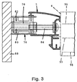
- the compensation profile 76 is preferably designed as a U-profile and contains two parallel legs 80, 82, the lower leg 82 according to the drawing on the inner surface of the inner leg 20 of the first profile 1 is present.
- the connecting body 78 is preferably made of plastic and enables the adjustment in cooperation with a connecting element 84 the compensation profile 76 in the direction of arrow 86 with respect to the first profile 1.
- the compensation profile 76 is for example on a room wall 88 by means of screws and dowels attached in a known manner.
- the connecting element 84 is in the area of its head 90 in a corresponding recess in the connecting axis arm 22 rotatably fixed, while the connecting body 78 with the compensation profile 76th is connected, as indicated by dash-dotted lines 92. Can be seen thus the first profile 1 on the room wall 88 or the like in the desired Mounted in this way and precisely adjusted.
- Fig. 3 basically corresponds to Fig. 2, but with the compensation profile 76 in one is shown from the first profile 1 moved out position. This was done by Rotate the connecting element 84, which is designed as a screw bolt and which is connected to its external thread into a corresponding internal thread of the connecting body 78 engages. The distance between the first profile 1 and the room wall 88 and thus the entire Frame of the shower partition with the three sliding doors, which are dash-dotted Lines 96, 97, 98 are indicated, and with the lower rail 4 is accordingly enlarged.
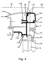
- Fig. 4 shows an installation situation of the first profile 1 and the second profile 2 in Connection area of a bathtub 100 to the shower tray 12, the outer contours with dash-dotted lines are indicated.
- a Connection profile 102 is provided, which has an outer body 104 between the free End edges 26 and 37 of the two profiles 1 and 2 has.
- the connection profile 102 contains a cross bar 106, which is on the one hand on the extension leg 52 of the first Profile 1 is supported and on the other hand, the second profile 2 with his Cross leg 38 or its web 46 and the portion 44 is supported.
- the outer end 104 of the connecting profile 102 is partially at its lower end on the edge of the bathtub 100 while the other part of the outer body 104 extended down on the tub edge of the shower tray 12 stands up.
- connection profile 102 contains also a channel or screw channel 108 corresponding to the channel or screw channel 50 of the second profile 2, with connecting elements not shown here or screw the connection of the two profiles 1, 2 with and over the connection profile 102 is manufactured.
- outer body 104 contains a web 110 and an open groove 112, the web 110 in the longitudinal groove 28 of the outer leg 18th engages and in the groove 112 of the web 36 of the outer leg 32 of the second profile 2nd
- the second connection profile 114 is in principle L-like trained and contains webs and grooves for contacting and supporting the corresponding Parts of the two profiles 1 and 2.
- the two profiles 1 and 2 are between a fixed room wall 88 and the fixed wall element 14, the Plate 16 in turn in the U-shaped groove of the portion 44 of the second profile 2nd is inserted.
- the first profile 1 is on the extension leg 52 and the Connection area between the outer leg 18 and the connecting leg 22 or the web 58 provided there is supported on the wall 88.
- webs 58 and 54 lie in the same plane, which is essentially runs orthogonal to the longitudinal plane 30. Furthermore, is particularly useful Way in the connection area of the extension leg 52 to the inner leg 20 to the wall 88 opening channel 115 is provided, which is preferably a screw channel is formed and in particular a connection to the wall 88 or others Components enabled.
- Fig. 6 shows the second profile 2 in combination with a connection profile 116 for one Ceiling support 118.
- the ceiling support 118 is telescopic inside the preferred annular connecting profile 116 arranged movably, but not further here shown means a lock can be carried out.
- the second profile 2 is between the connection profile 116 and the fixed wall element 14 with the plate 16 arranged.
- To connect the connection profile 116 with the second profile 2 again a screw or the like according to the dash-dotted line 120 in the channel 50 of the second profile 2 anchored.
- Fig. 7 shows a special use of the two profiles 1 and 2 for Aligning the wall element 16 at a predeterminable angle to one through the first Profile 1 predetermined level 122.
- the two profiles 1, 2 are joint profiles 124, 126 connected, which contain mutually corresponding joint bodies 128, 130.
- the outer joint body 128 surrounds the over a predetermined angular range other joint body 130 such that the wall element 14 in an angular range 132nd is adjustable with respect to said level 122.
- the two are Joint profiles 124, 126 supported on the assigned profile 1 or 2 and by means of analog Connecting elements, webs or the like connected together.
- a door wing of the shower partition can also be used with the angular range be connected to the first profile 1.
- Fig. 8 shows an application of the modified first profile 1 with the second Profile 2.
- the slightly opposite first profile 1 shown here again shows the basically U-shaped cross-section, but does not contain the above Extension leg. Since the inner leg 20 of the first profile 1 on the inside of the outer leg 24 of the second profile 2 abuts, which in turn with the web 46 is supported on the outside of the inner leg 20, is nevertheless a stable connection of the Profiles 1 and 2 guaranteed.
- the two profiles 1 and 2 are between as corner posts two fixed wall elements 14, 14 'arranged and by means of the connecting body 78, which is shown exploded detached from the interior the connection between the two profiles 1 and 2 specified. Furthermore, it is Cross-sectional area 133 of the lower profile rail 15 of the fixed wall element 14 indicated by rotation in the drawing plane.
- FIGS. 9 and 10 show an application of the first profile 1 for connecting the fixed wall element 14 at different angles to one here schematically indicated space wall 88.
- a hinge profile 134 is connected to the first profile 1, the installation depth by means of the connecting body 78 and the compensation profile 76 can be specified in accordance with the requirements.
- the hinge profile 134 is by means of here Screws and the like, not shown, with the compensation profile 76 and / or the connecting body 78 firmly connected.
- the one with the fixed one A further joint profile 136 is assigned to the joint element 134 connected to the wall element, with mutually corresponding and interlocking joint bodies are provided.
- a swivel range is predefined in accordance with the angle 140, so that the wall element 14 in the required manner with respect to the room wall 88 can be arranged.
- Said angular range 140 which is characterized by the Room wall connected joint profile 136 is specified, is not symmetrical to Center plane 142 of said joint profile 136, but offset to one side.
- the Joint profile 136 in FIG. 10 is at 180 ° in comparison to the position of FIG. 9 rotated position with respect to the room wall 88 is provided. So the connection can of the fixed wall element 14 on the room wall 88 with the same profiles can be mounted over a total angle of more than 180 °, although a stable and tight connection is ensured.
Landscapes
- Health & Medical Sciences (AREA)
- Public Health (AREA)
- Epidemiology (AREA)
- General Health & Medical Sciences (AREA)
- Residential Or Office Buildings (AREA)
- Devices For Medical Bathing And Washing (AREA)
- Soy Sauces And Products Related Thereto (AREA)
- Casings For Electric Apparatus (AREA)
- Patch Boards (AREA)
- Domestic Plumbing Installations (AREA)
Applications Claiming Priority (2)
| Application Number | Priority Date | Filing Date | Title |
|---|---|---|---|
| DE29905125U DE29905125U1 (de) | 1999-03-22 | 1999-03-22 | Bausatz für Duschabtrennungen |
| DE29905125U | 1999-03-22 |
Publications (3)
| Publication Number | Publication Date |
|---|---|
| EP1038486A2 true EP1038486A2 (fr) | 2000-09-27 |
| EP1038486A3 EP1038486A3 (fr) | 2002-02-06 |
| EP1038486B1 EP1038486B1 (fr) | 2006-05-17 |
Family
ID=8071138
Family Applications (1)
| Application Number | Title | Priority Date | Filing Date |
|---|---|---|---|
| EP00105275A Expired - Lifetime EP1038486B1 (fr) | 1999-03-22 | 2000-03-14 | Jeu de pièces pour cloisons de douches |
Country Status (4)
| Country | Link |
|---|---|
| EP (1) | EP1038486B1 (fr) |
| AT (1) | ATE326168T1 (fr) |
| DE (2) | DE29905125U1 (fr) |
| ZA (1) | ZA200001414B (fr) |
Cited By (2)
| Publication number | Priority date | Publication date | Assignee | Title |
|---|---|---|---|---|
| EP1116468A3 (fr) * | 2000-01-13 | 2003-05-21 | Jeremy David Lenighan | Ensemble de cloison de douche |
| EP1679409A1 (fr) * | 2004-12-21 | 2006-07-12 | Geberit Technik Ag | Dispositif pour la fixation d'un article sanitaire |
Families Citing this family (2)
| Publication number | Priority date | Publication date | Assignee | Title |
|---|---|---|---|---|
| DE202009002906U1 (de) | 2009-03-04 | 2010-04-29 | Altura Leiden Holding B.V. | Verbindungsanordnung von Trennelementen |
| DE102014103206B4 (de) | 2014-03-11 | 2019-07-11 | Mepa-Pauli Und Menden Gmbh | Verfahren und Dichtanordnung zur Abdichtung eines Wannenrandes |
Family Cites Families (4)
| Publication number | Priority date | Publication date | Assignee | Title |
|---|---|---|---|---|
| DE8107393U1 (de) | 1981-03-14 | 1982-04-22 | Theiner, Dieter E., 6940 Weinheim | "verbindungsprofil fuer eine duschabtrennung" |
| DE3347917C1 (de) * | 1983-03-19 | 1986-01-23 | Heinz Georg Hünibach Thun Baus | Verbindung von zwei Profilschienen |
| DE4106116A1 (de) * | 1991-02-27 | 1992-09-03 | Semer Gmbh & Co Kg W | Rahmen fuer trennwaende, insbesondere fuer duschabtrennungen u. dgl. |
| DE9417351U1 (de) | 1993-10-29 | 1995-01-26 | A. Artweger Ges. m.b.H., Bad Ischl | Einstellbare Befestigungsvorrichtung für Plattenelemente |
-
1999
- 1999-03-22 DE DE29905125U patent/DE29905125U1/de not_active Expired - Lifetime
-
2000
- 2000-03-14 DE DE50012743T patent/DE50012743D1/de not_active Expired - Lifetime
- 2000-03-14 EP EP00105275A patent/EP1038486B1/fr not_active Expired - Lifetime
- 2000-03-14 AT AT00105275T patent/ATE326168T1/de active
- 2000-03-20 ZA ZA200001414A patent/ZA200001414B/xx unknown
Cited By (2)
| Publication number | Priority date | Publication date | Assignee | Title |
|---|---|---|---|---|
| EP1116468A3 (fr) * | 2000-01-13 | 2003-05-21 | Jeremy David Lenighan | Ensemble de cloison de douche |
| EP1679409A1 (fr) * | 2004-12-21 | 2006-07-12 | Geberit Technik Ag | Dispositif pour la fixation d'un article sanitaire |
Also Published As
| Publication number | Publication date |
|---|---|
| EP1038486B1 (fr) | 2006-05-17 |
| ATE326168T1 (de) | 2006-06-15 |
| DE29905125U1 (de) | 1999-06-10 |
| ZA200001414B (en) | 2000-10-20 |
| EP1038486A3 (fr) | 2002-02-06 |
| DE50012743D1 (de) | 2006-06-22 |
Similar Documents
| Publication | Publication Date | Title |
|---|---|---|
| DE3705433C2 (fr) | ||
| DE2706013C2 (de) | Treibstangenbeschlag an Fenstern, Türen od.dgl. aus Metall- oder Kunststoffprofilen | |
| DE9413972U1 (de) | Lagerungselement für ein im wesentlichen plattenförmiges Bauteil | |
| EP0384224B1 (fr) | Dispositif de guidage | |
| DE3039499C2 (fr) | ||
| DE102015116192B3 (de) | Bandaufnahmeteil für ein verdeckt liegendes Bandsystem für Türen oder Fenster und Türband mit dem Bandaufnahmeteil | |
| EP0285914A2 (fr) | Séparation de douche | |
| CH670555A5 (fr) | ||
| DE7830415U1 (de) | Fluegelgelenkband fuer fenster, tueren o.dgl. | |
| DE102019100538B3 (de) | Gebäudetür und Türband | |
| DE2405620C2 (de) | Ecklager für Fenster, Türen od. dgl. insbesondere mit Drehkippflügel | |
| EP0784956A1 (fr) | Cloison de douche | |
| EP0118050B1 (fr) | Dispositif de réglage d'une penture de paumelle | |
| DE3104973A1 (de) | "aufschraubband, insbesondere fuer schwere fenster- oder tuerfluegel mit kunststoffprofilen" | |
| EP1038486B1 (fr) | Jeu de pièces pour cloisons de douches | |
| DE8809618U1 (de) | Duschabtrennung | |
| DE102012111547B3 (de) | Türband | |
| EP1243212B1 (fr) | Cloison de douche | |
| EP0552721A1 (fr) | Fenêtre à aile à rabattement | |
| DE19607931C2 (de) | Dachfenster | |
| DE9202441U1 (de) | Duschabtrennung | |
| DE202005010513U1 (de) | Schwenktür mit einer Halterung zur Einspannung einer Glasscheibe und eine Duschabtrennung mit einer solchen Schwenktür | |
| DE3526288C2 (fr) | ||
| DE20211901U1 (de) | Trennwand | |
| DE2645671A1 (de) | Deckengliedertor |
Legal Events
| Date | Code | Title | Description |
|---|---|---|---|
| PUAI | Public reference made under article 153(3) epc to a published international application that has entered the european phase |
Free format text: ORIGINAL CODE: 0009012 |
|
| AK | Designated contracting states |
Kind code of ref document: A2 Designated state(s): AT BE CH CY DE DK ES FI FR GB GR IE IT LI LU MC NL PT SE |
|
| AX | Request for extension of the european patent |
Free format text: AL;LT;LV;MK;RO;SI |
|
| PUAL | Search report despatched |
Free format text: ORIGINAL CODE: 0009013 |
|
| AK | Designated contracting states |
Kind code of ref document: A3 Designated state(s): AT BE CH CY DE DK ES FI FR GB GR IE IT LI LU MC NL PT SE |
|
| AX | Request for extension of the european patent |
Free format text: AL;LT;LV;MK;RO;SI |
|
| 17P | Request for examination filed |
Effective date: 20020307 |
|
| AKX | Designation fees paid |
Free format text: AT BE CH CY DE DK ES FI FR GB GR IE IT LI LU MC NL PT SE |
|
| 17Q | First examination report despatched |
Effective date: 20041115 |
|
| GRAP | Despatch of communication of intention to grant a patent |
Free format text: ORIGINAL CODE: EPIDOSNIGR1 |
|
| GRAS | Grant fee paid |
Free format text: ORIGINAL CODE: EPIDOSNIGR3 |
|
| GRAA | (expected) grant |
Free format text: ORIGINAL CODE: 0009210 |
|
| AK | Designated contracting states |
Kind code of ref document: B1 Designated state(s): AT BE CH CY DE DK ES FI FR GB GR IE IT LI LU MC NL PT SE |
|
| PG25 | Lapsed in a contracting state [announced via postgrant information from national office to epo] |
Ref country code: IE Free format text: LAPSE BECAUSE OF FAILURE TO SUBMIT A TRANSLATION OF THE DESCRIPTION OR TO PAY THE FEE WITHIN THE PRESCRIBED TIME-LIMIT Effective date: 20060517 Ref country code: FI Free format text: LAPSE BECAUSE OF FAILURE TO SUBMIT A TRANSLATION OF THE DESCRIPTION OR TO PAY THE FEE WITHIN THE PRESCRIBED TIME-LIMIT Effective date: 20060517 Ref country code: GB Free format text: LAPSE BECAUSE OF FAILURE TO SUBMIT A TRANSLATION OF THE DESCRIPTION OR TO PAY THE FEE WITHIN THE PRESCRIBED TIME-LIMIT Effective date: 20060517 Ref country code: IT Free format text: LAPSE BECAUSE OF FAILURE TO SUBMIT A TRANSLATION OF THE DESCRIPTION OR TO PAY THE FEE WITHIN THE PRESCRIBED TIME-LIMIT;WARNING: LAPSES OF ITALIAN PATENTS WITH EFFECTIVE DATE BEFORE 2007 MAY HAVE OCCURRED AT ANY TIME BEFORE 2007. THE CORRECT EFFECTIVE DATE MAY BE DIFFERENT FROM THE ONE RECORDED. Effective date: 20060517 |
|
| REG | Reference to a national code |
Ref country code: GB Ref legal event code: FG4D Free format text: NOT ENGLISH |
|
| REG | Reference to a national code |
Ref country code: CH Ref legal event code: EP |
|
| REG | Reference to a national code |
Ref country code: IE Ref legal event code: FG4D Free format text: LANGUAGE OF EP DOCUMENT: GERMAN |
|
| REF | Corresponds to: |
Ref document number: 50012743 Country of ref document: DE Date of ref document: 20060622 Kind code of ref document: P |
|
| PG25 | Lapsed in a contracting state [announced via postgrant information from national office to epo] |
Ref country code: DK Free format text: LAPSE BECAUSE OF FAILURE TO SUBMIT A TRANSLATION OF THE DESCRIPTION OR TO PAY THE FEE WITHIN THE PRESCRIBED TIME-LIMIT Effective date: 20060817 Ref country code: SE Free format text: LAPSE BECAUSE OF FAILURE TO SUBMIT A TRANSLATION OF THE DESCRIPTION OR TO PAY THE FEE WITHIN THE PRESCRIBED TIME-LIMIT Effective date: 20060817 |
|
| PG25 | Lapsed in a contracting state [announced via postgrant information from national office to epo] |
Ref country code: ES Free format text: LAPSE BECAUSE OF FAILURE TO SUBMIT A TRANSLATION OF THE DESCRIPTION OR TO PAY THE FEE WITHIN THE PRESCRIBED TIME-LIMIT Effective date: 20060828 |
|
| PG25 | Lapsed in a contracting state [announced via postgrant information from national office to epo] |
Ref country code: PT Free format text: LAPSE BECAUSE OF FAILURE TO SUBMIT A TRANSLATION OF THE DESCRIPTION OR TO PAY THE FEE WITHIN THE PRESCRIBED TIME-LIMIT Effective date: 20061017 |
|
| ET | Fr: translation filed | ||
| GBV | Gb: ep patent (uk) treated as always having been void in accordance with gb section 77(7)/1977 [no translation filed] |
Effective date: 20060517 |
|
| REG | Reference to a national code |
Ref country code: IE Ref legal event code: FD4D |
|
| PLBE | No opposition filed within time limit |
Free format text: ORIGINAL CODE: 0009261 |
|
| STAA | Information on the status of an ep patent application or granted ep patent |
Free format text: STATUS: NO OPPOSITION FILED WITHIN TIME LIMIT |
|
| 26N | No opposition filed |
Effective date: 20070220 |
|
| PG25 | Lapsed in a contracting state [announced via postgrant information from national office to epo] |
Ref country code: MC Free format text: LAPSE BECAUSE OF NON-PAYMENT OF DUE FEES Effective date: 20070331 |
|
| PG25 | Lapsed in a contracting state [announced via postgrant information from national office to epo] |
Ref country code: CY Free format text: LAPSE BECAUSE OF FAILURE TO SUBMIT A TRANSLATION OF THE DESCRIPTION OR TO PAY THE FEE WITHIN THE PRESCRIBED TIME-LIMIT Effective date: 20060517 Ref country code: LU Free format text: LAPSE BECAUSE OF NON-PAYMENT OF DUE FEES Effective date: 20070314 |
|
| PGFP | Annual fee paid to national office [announced via postgrant information from national office to epo] |
Ref country code: FR Payment date: 20110401 Year of fee payment: 12 Ref country code: NL Payment date: 20110328 Year of fee payment: 12 |
|
| PG25 | Lapsed in a contracting state [announced via postgrant information from national office to epo] |
Ref country code: GR Free format text: LAPSE BECAUSE OF NON-PAYMENT OF DUE FEES Effective date: 20070331 |
|
| REG | Reference to a national code |
Ref country code: NL Ref legal event code: V1 Effective date: 20121001 |
|
| REG | Reference to a national code |
Ref country code: FR Ref legal event code: ST Effective date: 20121130 |
|
| PG25 | Lapsed in a contracting state [announced via postgrant information from national office to epo] |
Ref country code: FR Free format text: LAPSE BECAUSE OF NON-PAYMENT OF DUE FEES Effective date: 20120402 |
|
| PG25 | Lapsed in a contracting state [announced via postgrant information from national office to epo] |
Ref country code: NL Free format text: LAPSE BECAUSE OF NON-PAYMENT OF DUE FEES Effective date: 20121001 |
|
| REG | Reference to a national code |
Ref country code: DE Ref legal event code: R082 Ref document number: 50012743 Country of ref document: DE Representative=s name: REBLE KLOSE SCHMITT PARTNERSCHAFTSGESELLSCHAFT, DE |
|
| PGFP | Annual fee paid to national office [announced via postgrant information from national office to epo] |
Ref country code: CH Payment date: 20170327 Year of fee payment: 18 |
|
| PGFP | Annual fee paid to national office [announced via postgrant information from national office to epo] |
Ref country code: AT Payment date: 20170322 Year of fee payment: 18 Ref country code: BE Payment date: 20170323 Year of fee payment: 18 |
|
| PGFP | Annual fee paid to national office [announced via postgrant information from national office to epo] |
Ref country code: DE Payment date: 20170331 Year of fee payment: 18 |
|
| REG | Reference to a national code |
Ref country code: DE Ref legal event code: R119 Ref document number: 50012743 Country of ref document: DE |
|
| REG | Reference to a national code |
Ref country code: CH Ref legal event code: PL |
|
| REG | Reference to a national code |
Ref country code: AT Ref legal event code: MM01 Ref document number: 326168 Country of ref document: AT Kind code of ref document: T Effective date: 20180314 |
|
| REG | Reference to a national code |
Ref country code: BE Ref legal event code: MM Effective date: 20180331 |
|
| PG25 | Lapsed in a contracting state [announced via postgrant information from national office to epo] |
Ref country code: DE Free format text: LAPSE BECAUSE OF NON-PAYMENT OF DUE FEES Effective date: 20181002 Ref country code: AT Free format text: LAPSE BECAUSE OF NON-PAYMENT OF DUE FEES Effective date: 20180314 |
|
| PG25 | Lapsed in a contracting state [announced via postgrant information from national office to epo] |
Ref country code: CH Free format text: LAPSE BECAUSE OF NON-PAYMENT OF DUE FEES Effective date: 20180331 Ref country code: BE Free format text: LAPSE BECAUSE OF NON-PAYMENT OF DUE FEES Effective date: 20180331 Ref country code: LI Free format text: LAPSE BECAUSE OF NON-PAYMENT OF DUE FEES Effective date: 20180331 |