EP1038489A2 - Installation de douches - Google Patents
Installation de douches Download PDFInfo
- Publication number
- EP1038489A2 EP1038489A2 EP00105446A EP00105446A EP1038489A2 EP 1038489 A2 EP1038489 A2 EP 1038489A2 EP 00105446 A EP00105446 A EP 00105446A EP 00105446 A EP00105446 A EP 00105446A EP 1038489 A2 EP1038489 A2 EP 1038489A2
- Authority
- EP
- European Patent Office
- Prior art keywords
- column
- traverse
- shower
- shower device
- angle
- Prior art date
- Legal status (The legal status is an assumption and is not a legal conclusion. Google has not performed a legal analysis and makes no representation as to the accuracy of the status listed.)
- Granted
Links
Images


Classifications
-
- A—HUMAN NECESSITIES
- A47—FURNITURE; DOMESTIC ARTICLES OR APPLIANCES; COFFEE MILLS; SPICE MILLS; SUCTION CLEANERS IN GENERAL
- A47K—SANITARY EQUIPMENT; ACCESSORIES THEREFOR, e.g. TOILET ACCESSORIES
- A47K3/00—Baths; Showers; Appurtenances therefor
- A47K3/28—Showers or bathing douches
Definitions
- the invention relates to a shower device, in particular a shower cubicle which has at least one laterally arranged has essentially vertical column, which in its upper Area at least one angle with at least one die shower device is connected to the superior traverse.
- a shower device of this type is known from the DE 39 01 162.
- This shower device has four vertical Columns, one of which struts to a middle one Knot piece comes off with an overhead shower. But there are the cross sections of the column and strut extreme different or the pillars many times thicker.
- the invention allows the column and crossbeam not only to be used same, but new with different cross sections be formed. By cutting at an angle a certain angle is an adjustment of the connection points possible together. An angle unequal to half The angle between the column and the crossbeam enables use different cross-sections while at the same time if possible elegant and even transition from pillar to crossbar. Alternatively, the transition can take place in several stages, for example with three or four intermediate angles, the sum of which is the final total angle between the column and Traverse determined, preferably at an angle between pillar and crossbar in this case one of the Intermediate angle should be understood.
- the oblique cuts of the column and the connected crossbar in the assembled state of the shower facility essentially parallel, preferably exactly parallel.
- This enables the traverse to be trained to be connected directly to the column or the bevel cuts to sit directly next to each other.
- each diagonal cut of the column and the cross beam according to Art a straight cut in one plane. It is possible that Form connection as a joint, preferably as a flat joint.
- the oblique cuts of the column and the traverse connected to it have the same outer contours have or define the same areas.
- the cross sections of the column and are particularly preferred Traverse derived from one another, in particular by a simple geometric transformation, e.g. a Stretching.
- a relationship of the cross sections can be found in it exist that in particular straight cuts through column and Traverse can be drawn using the same cut surfaces result, preferably identical cut surfaces.
- a cross section i.e. a vertical section, through a profile, an oblique cut through the other Match profile.
- the larger one Cross section from an oblique cut through the smaller one Cross-section can be derived.
- the at least one traverse horizontally and in particular approximately run at right angles to the vertical column.
- the angle to the other part can then be the difference to be 90 °.
- With a right-angled arrangement of The column and crossbar would normally be a bevel cut made at 45 °, so that according to the invention a clear Deviation from the usual.
- the cross sections of the column and the crossbeam are preferred rounded, being parabolic or elliptical in particular Have outer contours.
- the one derived from each other partially elliptical outer contours can each be the same Underlying circles.
- the cross sections are preferred at least convex to the outside, especially in the Interior of the shower facility.
- Convex arched Cross sections are visually appealing, easy to manufacture, stable and also allow through their relatively large size Internal volume the installation of various facilities.
- Especially the cross-section of the traverse is preferably flatter, especially less convexly curved, formed than the one the column to make the crossbar generally slimmer or with to design a cross section of smaller area.
- the Angle between the plane of the oblique cut of the traverse and its longitudinal axis is less than 40 °, in particular approximately 30 °.
- the cross sections of the column or the crossmember are advantageous essentially of two different convex strengths domed areas.
- the cross sections are preferably thicker outwards than into the interior of the shower facility arched, which on the one hand reduces the column and crossbeam protrude into the interior.
- pillars of this kind on a corner or a rounded outer boundary a shower device can be attached so that a stronger Curving outwards better the general shape of the shower facility is adjusted.
- the cross sections of the column and / or the crossmember can be symmetrical be, preferably axisymmetric or symmetrical to one level.
- the cross sections in assembled state symmetrical to the same plane.
- At this preferred embodiment have the column and crossbar same width.
- a hollow profile consists preferably of plastic or light metal.
- Such an washer can, on the one hand Complete the sharp outer edges of the column and the crossbeam or cover, in particular a transition from the Column to the traverse, possibly with an adjustment to one smooth transition, can form.
- the washer with the column and / or the crossbar to connect, preferably with both.
- a holding function can, for example, on both sides, in the Cross sections of the column or the crossbar engaging and on the inner sides of which are adjacent projections.
- the essential Connection can preferably or the like via screws. be made stable.
- the at least one pillar is preferably in the corner area or in a protruding area of the shower facility or one Shower tray arranged, in particular it can on the edge of the shower tray placed and fastened.
- the traverse can protrude beyond the central area of the shower facility or cross them to another edge area, in particular end above a corner area opposite the column.
- a corner shower for installation in a corner wall the traverse can run into the corner. Preferably it is attached in the corner, especially with at least one of the corner walls connected. For exact adjustment as well as for manufacturing reasons, a variable length applies Connection as particularly advantageous.
- the column preferably carries at least one functional unit, for example water flow regulator, mixer, thermostat and / or diverter. Furthermore, with at least be connected to a shower or have it, in particular an edge shower and / or at least one side shower.
- a functional unit for example water flow regulator, mixer, thermostat and / or diverter.
- the at least one traverse can be at least partially to train water, in particular they are water-bearing can be connected to the column.
- a flow of water or a water-bearing connection preferably runs within the traverse and / or the column.
- the traverse is connected to a water supply via the column and via one of the aforementioned functional units, taking the pillar advantageously from below with shower water is supplied, for example over the edge of a shower tray.
- the traverse can be used functionally, in particular carry at least one shower function unit, for example a shower head.
- lighting means especially low voltage lights at the Traverse be attached, a power supply advantageous according to the type of water supply.
- FIG. 1 shows an oblique view from above of a shower device 11, formed in the manner of a corner shower in a corner 12 of two walls 13, is installed.
- a vertical column 16 is attached, which with a in the Corner 12 attached cross member 17 is connected.
- Shower partition 19 Access to the shower facility 11 takes place via a door 20 which struck the other wall 13 and closes against the other side of the column 16.
- the Walls 13 can be standard bathroom walls.
- the shower partition 19 and the door 20 can be made of flat elements, for example Glass panes are made using holding rails 21 are attached to the walls 13 and the column 16.
- Dashed lines are shown on the inside of the column 16 attached functional units such as a diverter mixing unit 22, two side showers 23 and a hand shower 24.
- the Traverse 17 bears a screen 26 in the middle, which points downward hanging and it is partially non-gripping.
- the Umbrella 26 has an overhead shower 27 which is connected to the diverter mixing unit 22 is connected to carry water.
- dashed two on the underside of the traverse 17 drawn radiator 28 attached to the not shown Are connected to a power supply.
- the traverse 17 on her in the corner 12 reaching end has a push-over sleeve 18, which is adapted to the angle of the corner 12. Details 5 can be seen from this. You can see that further the bevel cut 25, on the column 16 and traverse 17 are connected.
- the plane of the bevel cuts 25 is perpendicular to the Level, along the column 16 and traverse 17.
- Cross sections not only by stretching a cross section in one direction, but also in a second direction to derive.
- Particularly unusual designs can be created by a pivoting of the plane of the inclined sections 25 opposite that level can be achieved, so to speak by a double tilted section of the profiles of the column 16 and the Truss 17.
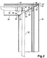
- Fig. 2 shows a section through the column 16 and Traverse 17 in the area of their connection. It is clearly too recognize that the cross section of the horizontal traverse 17th is considerably flatter than that of column 16, shown in more detail is this in FIGS. 3 and 4.
- the bevel cuts 25 are parallel at an angle of 30 ° to the longitudinal axis of the Traverse 17 executed. Between the bevel cuts 25 or the butt joint of the column 16 with the cross member 17 is one Washer 30 inserted in different directions has extending ribs 31. It can be seen that the Washer essentially in the manner of a relative narrow and thin ring is formed. You can out Be made of plastic. It dominates the outer edges of the Bevel cuts 25 with their edge by a small amount. Due to the ribs 31, the washer 30 is in each case immovable on the bevel cuts 25 and thus causes that the traverse 17 is not opposite to that encountered Pillar 16 can be moved.
- the ribs 31 in different directions run, especially at right angles to each other.
- a a particularly stable design can essentially Provide a closed washer, with the ribs in approximately at right angles to each other over the entire area run.
- the butt joint is released by the Fixing screw 32 prevented by the upper Outer wall of the cross member 17 into a thread 33 in the column 16 intervenes.
- the thread 33 is preferably a round groove 3, see FIG. 3.
- FIG. 16 a water-carrying connection is shown in FIG the column 16 and the traverse 17 shown by, for example the overhead shower 27 of the traverse to the diverter mixing unit 22 of the column can be connected.
- the connection consists of two tubes 35, the tube 35 in the column 16 over the plane of the bevel cuts 25 or extends upwards through the intermediate disk 30. He points at its end an angled insert 36, which in a clutch 37 opens.
- the hose 35 of the traverse 17 has an insert carrying a coupling plug 38.
- the tubes 35 can be substantially loose within the Profiles of the column 16 and the traverse 17 run.
- a Connection is, for example, in the area of the washer 30 advantageous, especially the hose 35 of column 16 does not collapse downwards and is no longer available.
- An attachment can for example a pinch in a corresponding eyelet on the washer 30, this attachment is not a large one Needs to take over.
- Fig. 3 shows the profile of the column 16 in cross section. It consists of two convex, essentially elliptical shaped areas, with the upper area essential is more domed than the lower one, which is rather flat.
- the strongly curved area is preferably outside of the shower facility 11, while the flat arched in the interior can point. Both areas meet on the side edges at an angle to each other that is approximately 90 °.
- the upper tip of the strongly arched area has an inside extending partition 40 on, to stabilize the Pillar 16, for attaching functional units like that Diverter mixing unit 22 and to form the longitudinal eyelet 41 for the thread 33 into which the fastening screw 32 engages, is trained. Furthermore stand from the inside two eyelets 43 into the bolts for fastening the column 16 can be screwed into the shower tray 15.
- flags 44 are used in the area of the functional units or the diverter mixing unit 22 the weak detach the arched area of the column 16 and from the front pressed against the flag 44 a control panel or the like. to use. In principle, it is possible to divide the partition 40, the eyelets 41 and 43 and the flags 44 only in the Areas where they are needed.
- a continuous training advantageously increases the one Stability of the column 16, on the other hand it corresponds to one Production method by a continuous casting process.
- Fig. 4 shows the profile of the cross member 17 in cross section. It can be clearly seen that their profile also consists of one more domed, in Fig. 4 upper area and one very slightly domed area. The angle in the edge area is correspondingly smaller and is approx. 70 ° to 80 °. The width is the same as that of column 16, only the height is slightly lower. In the middle of the strong domed area is a fastening eyelet on the inside 46, similar to the eyelets 41 or 43 in Fig. 3, molded. Their function is explained in Fig. 5. Because of the special Formation of the bevel cuts 25 and the matching Profiles of the column 16 and the traverse 17 to the Oblique cuts come through from the profile of the column 16 scale compression in height to the profile of the traverse 17. The compression here is about 40% and can be done using Trigonometry from the angle between the bevel cut 25 and the traverse 17 can be calculated.
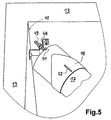
- FIG. 5 is an enlarged view of the attachment the traverse 17 in the corner 12.
- a mounting bracket 48 screwed across the corner 12.
- a screw pin 49 engages in it, with two Nuts against the mounting bracket 48 is countered.
- the Screw bolt 49 is in the fastening eye shown in FIG. 4 46 turned.
- An adjustment of the attachment is due to the available length of the bolt 49 possible to adjust the distance between the column 16 and the corner 12.
- the cuff 18 is guided over the crossmember 17, which is pushed into corner 12 after the crossbar has been attached and the open end of the traverse and its Fastening covered.
- the cuff 18 is fixed by means of an adjusting screw 51 through an adjusting slot 52 screwed into the crossmember 17 at the top of the sleeve is.
- the fit of the sleeve 18 in the corner 12 is by means of of the adjustment slot 52 adjustable. So the pillar is 16 both with the shower tray 15 and the crossbar 17 connected to corner 12. The gets additional stability shower device 11 through the connection of the column 16 the shower partition 19 with the wall 12, so that the construction overall is stable for the intended purpose.
- the column 16 preferably also the traverse, runs advantageously straightforward.
- Alternative designs for one Traverses can provide a curved course, either by several bends or by constant bending, for example similar to an arc lamp.
- the angular condition applies to the attachment of the traverse to the column.
- a structure of the shower device 11 shown in FIG. 1 can be as follows:
- the column 16 is placed on an installed shower tray 15, being both a water connection to a hot and cold water pipe as well as possibly a cable connection for the spotlights 28 is connected.
- the connection between the connections can or the like by plug-in couplings. respectively.
- Attached the column is fastened by means of fastening bolts screwed into the eyelets 43, that reach through the wall of the shower tray and screwed to it.
- Next up is the corresponding point in the corner 12 of the mounting bracket 48 mounted.
- the traverse 17 with the striped cuff is with the screwed screw 49, on the a nut is already guided to the mounting bracket 48 hung and the hoses 35 over the coupling connection 37 and 38 connected.
- the traverse 17 is on the column 16 or the inserted washer 30 and with the Fastening screw 32 connected to the column 16.
- the distance between the column 16 and the corner 12 can be adjusted or the column should be directed vertically, using adjustment the bolt 49 by means of nuts against the Mounting bracket 48. Place in the correct position the nuts tighten the bolts 49. Then the Cuff 18 pushed as far as possible into the corner 12 and by means of the adjusting screw reaching through the adjusting slot 52 51 fixed. Finally, the shower partition 19 and the door 20 mounted by means of the holding rails 21. The shower device 11 is thus completely finished.
- the column 16 is usually delivered in a preassembled state, i.e. the functional units such as diverter mixing unit 22, side showers 23 and possibly also the hand shower 24 are already pre-assembled. Furthermore, the hose 35 inserted.
- the shower tray 15 it is possible to use the corner 12 or to design a wall 13 and the traverse 17 in the column 16. It is advantageous for a water supply via the Corner or wall possible, in the area of the cover sleeve 18 easily accessible shut-off valves, especially for pre-shut-off, to be provided for the water supply. So it can Assembly can be facilitated. Such care can be particularly advantageous for walls 13 that are specifically for the shower device 11 are erected. In this way a shower tray 15 can be used without openings or the shower device 11 on a tiled bathroom floor being constructed.
Landscapes
- Health & Medical Sciences (AREA)
- Public Health (AREA)
- Epidemiology (AREA)
- General Health & Medical Sciences (AREA)
- Bathtubs, Showers, And Their Attachments (AREA)
- Steps, Ramps, And Handrails (AREA)
- Body Structure For Vehicles (AREA)
- Component Parts Of Construction Machinery (AREA)
- Massaging Devices (AREA)
- Devices That Are Associated With Refrigeration Equipment (AREA)
- Vehicle Body Suspensions (AREA)
Applications Claiming Priority (2)
| Application Number | Priority Date | Filing Date | Title |
|---|---|---|---|
| DE19912323A DE19912323A1 (de) | 1999-03-19 | 1999-03-19 | Duscheinrichtung |
| DE19912323 | 1999-03-19 |
Publications (3)
| Publication Number | Publication Date |
|---|---|
| EP1038489A2 true EP1038489A2 (fr) | 2000-09-27 |
| EP1038489A3 EP1038489A3 (fr) | 2001-06-27 |
| EP1038489B1 EP1038489B1 (fr) | 2005-06-01 |
Family
ID=7901588
Family Applications (1)
| Application Number | Title | Priority Date | Filing Date |
|---|---|---|---|
| EP00105446A Expired - Lifetime EP1038489B1 (fr) | 1999-03-19 | 2000-03-15 | Installation de douches |
Country Status (4)
| Country | Link |
|---|---|
| EP (1) | EP1038489B1 (fr) |
| AT (1) | ATE296569T1 (fr) |
| DE (2) | DE19912323A1 (fr) |
| ES (1) | ES2243164T3 (fr) |
Families Citing this family (2)
| Publication number | Priority date | Publication date | Assignee | Title |
|---|---|---|---|---|
| ITTV20070166A1 (it) * | 2007-10-02 | 2009-04-03 | Jacuzzi Europ | Colonna per cabina doccia |
| DE102007053338B4 (de) * | 2007-11-08 | 2012-01-19 | A & S Bäder GmbH & Co. | Sanitärinstallationssystem |
Citations (1)
| Publication number | Priority date | Publication date | Assignee | Title |
|---|---|---|---|---|
| DE3901162A1 (de) | 1989-01-17 | 1990-07-19 | Grohe Kg Hans | Duscheinrichtung |
Family Cites Families (6)
| Publication number | Priority date | Publication date | Assignee | Title |
|---|---|---|---|---|
| DE4033517A1 (de) * | 1989-12-20 | 1991-06-27 | Wolfram Elwert | Rund-duschkabine |
| DE9001977U1 (de) * | 1990-02-20 | 1990-04-26 | Horntrich, Günter, 75172 Pforzheim | Blende zum Abdecken von Teilen |
| DE4031990C2 (de) * | 1990-10-09 | 1995-04-13 | Schulte Duschkabinen | Duschabtrennung |
| DE4112596A1 (de) * | 1991-04-18 | 1992-10-22 | Winfried Noth | Duschkabine |
| FR2702138B1 (fr) * | 1993-03-02 | 1995-05-19 | Algue Sa | Cabine de douche à bac-receveur, avec mât et potence de montage des parois mobiles. |
| DE19701847C2 (de) * | 1997-01-21 | 2002-11-14 | Hansgrohe Ag | Duscheinrichtung |
-
1999
- 1999-03-19 DE DE19912323A patent/DE19912323A1/de not_active Withdrawn
-
2000
- 2000-03-15 ES ES00105446T patent/ES2243164T3/es not_active Expired - Lifetime
- 2000-03-15 DE DE50010424T patent/DE50010424D1/de not_active Expired - Fee Related
- 2000-03-15 EP EP00105446A patent/EP1038489B1/fr not_active Expired - Lifetime
- 2000-03-15 AT AT00105446T patent/ATE296569T1/de not_active IP Right Cessation
Patent Citations (1)
| Publication number | Priority date | Publication date | Assignee | Title |
|---|---|---|---|---|
| DE3901162A1 (de) | 1989-01-17 | 1990-07-19 | Grohe Kg Hans | Duscheinrichtung |
Also Published As
| Publication number | Publication date |
|---|---|
| DE19912323A1 (de) | 2000-09-21 |
| EP1038489A3 (fr) | 2001-06-27 |
| ES2243164T3 (es) | 2005-12-01 |
| DE50010424D1 (de) | 2005-07-07 |
| EP1038489B1 (fr) | 2005-06-01 |
| ATE296569T1 (de) | 2005-06-15 |
Similar Documents
| Publication | Publication Date | Title |
|---|---|---|
| DE69908576T2 (de) | Verbindungsvorrichtung | |
| DE9102252U1 (de) | Verbindungssystem für zwei als Rohr- oder Stangen- und/oder Knotenelemente ausgebildete Bauteile | |
| WO1988003203A2 (fr) | Systeme modulaire de construction | |
| EP1849929A2 (fr) | Auvent en porte-à-faux | |
| DE69309756T2 (de) | Anschlusselement für Bauprofile und Konstruktionen, die mittels solcher Anschlusselemente verbundene Bauprofile enthalten | |
| EP0619091B1 (fr) | Poteau de fixation pour fixer et/ou renforcer des parois pour cabines de douche | |
| DE202006003836U1 (de) | Deckenschalungssystem | |
| EP0016958B1 (fr) | Profilé de cadre pour fenêtre, porte ou analogue | |
| EP1589862B1 (fr) | Ensemble de douche | |
| EP1038489B1 (fr) | Installation de douches | |
| EP0610479B1 (fr) | Rail d'ancrage pour la technique du batiment | |
| EP0811099B1 (fr) | Coffrage avec element de coffrage en voute | |
| EP1439269A1 (fr) | Etrier d'ancrage pour profilés pour installations sanitaires et chassis avec un tel étrier | |
| EP3251570A1 (fr) | Dispositif de fixation et agrégat de douche | |
| DE4406647A1 (de) | Duschabtrennung | |
| EP1428941B1 (fr) | Dispositif de fixation d'un article sanitaire | |
| CH663817A5 (de) | Bauelementensatz zur herstellung eines gitters. | |
| WO1999035948A1 (fr) | Systeme de revetement pour cuve, de preference pour baignoire | |
| DE20001681U1 (de) | Griffstangen-Anordnung | |
| EP0130354A2 (fr) | Comptoir modulaire préfabriqué | |
| DE19931041C2 (de) | Unterkonstruktion für ein Verkleidungssystem für eine Wanne | |
| DE10136348C1 (de) | Halterung für eine ausrichtbare Befestigung der Stützen eines Balkongeländers | |
| DE29821761U1 (de) | Verkleidungssystem für eine Wanne, vorzugsweise Badewanne | |
| DE202004001227U1 (de) | Vorrichtung zum Verbinden von wenigstens zwei strangartigen Hohlprofilen | |
| DE7234902U (de) | Türzarge aus Metall oder Kunststoff |
Legal Events
| Date | Code | Title | Description |
|---|---|---|---|
| PUAI | Public reference made under article 153(3) epc to a published international application that has entered the european phase |
Free format text: ORIGINAL CODE: 0009012 |
|
| AK | Designated contracting states |
Kind code of ref document: A2 Designated state(s): AT BE CH CY DE DK ES FI FR GB GR IE IT LI LU MC NL PT SE |
|
| AX | Request for extension of the european patent |
Free format text: AL;LT;LV;MK;RO;SI |
|
| PUAL | Search report despatched |
Free format text: ORIGINAL CODE: 0009013 |
|
| AK | Designated contracting states |
Kind code of ref document: A3 Designated state(s): AT BE CH CY DE DK ES FI FR GB GR IE IT LI LU MC NL PT SE |
|
| AX | Request for extension of the european patent |
Free format text: AL;LT;LV;MK;RO;SI |
|
| 17P | Request for examination filed |
Effective date: 20011114 |
|
| AKX | Designation fees paid |
Free format text: AT BE CH CY DE DK ES FI FR GB GR IE IT LI LU MC NL PT SE |
|
| 17Q | First examination report despatched |
Effective date: 20040511 |
|
| GRAP | Despatch of communication of intention to grant a patent |
Free format text: ORIGINAL CODE: EPIDOSNIGR1 |
|
| GRAS | Grant fee paid |
Free format text: ORIGINAL CODE: EPIDOSNIGR3 |
|
| GRAA | (expected) grant |
Free format text: ORIGINAL CODE: 0009210 |
|
| AK | Designated contracting states |
Kind code of ref document: B1 Designated state(s): AT BE CH CY DE DK ES FI FR GB GR IE IT LI LU MC NL PT SE |
|
| PG25 | Lapsed in a contracting state [announced via postgrant information from national office to epo] |
Ref country code: FI Free format text: LAPSE BECAUSE OF FAILURE TO SUBMIT A TRANSLATION OF THE DESCRIPTION OR TO PAY THE FEE WITHIN THE PRESCRIBED TIME-LIMIT Effective date: 20050601 Ref country code: NL Free format text: LAPSE BECAUSE OF FAILURE TO SUBMIT A TRANSLATION OF THE DESCRIPTION OR TO PAY THE FEE WITHIN THE PRESCRIBED TIME-LIMIT Effective date: 20050601 Ref country code: IE Free format text: LAPSE BECAUSE OF FAILURE TO SUBMIT A TRANSLATION OF THE DESCRIPTION OR TO PAY THE FEE WITHIN THE PRESCRIBED TIME-LIMIT Effective date: 20050601 |
|
| REG | Reference to a national code |
Ref country code: GB Ref legal event code: FG4D Free format text: NOT ENGLISH |
|
| REG | Reference to a national code |
Ref country code: CH Ref legal event code: EP |
|
| REG | Reference to a national code |
Ref country code: IE Ref legal event code: FG4D Free format text: LANGUAGE OF EP DOCUMENT: GERMAN |
|
| REF | Corresponds to: |
Ref document number: 50010424 Country of ref document: DE Date of ref document: 20050707 Kind code of ref document: P |
|
| GBT | Gb: translation of ep patent filed (gb section 77(6)(a)/1977) |
Effective date: 20050727 |
|
| PG25 | Lapsed in a contracting state [announced via postgrant information from national office to epo] |
Ref country code: DK Free format text: LAPSE BECAUSE OF FAILURE TO SUBMIT A TRANSLATION OF THE DESCRIPTION OR TO PAY THE FEE WITHIN THE PRESCRIBED TIME-LIMIT Effective date: 20050901 Ref country code: GR Free format text: LAPSE BECAUSE OF FAILURE TO SUBMIT A TRANSLATION OF THE DESCRIPTION OR TO PAY THE FEE WITHIN THE PRESCRIBED TIME-LIMIT Effective date: 20050901 Ref country code: SE Free format text: LAPSE BECAUSE OF FAILURE TO SUBMIT A TRANSLATION OF THE DESCRIPTION OR TO PAY THE FEE WITHIN THE PRESCRIBED TIME-LIMIT Effective date: 20050901 |
|
| PG25 | Lapsed in a contracting state [announced via postgrant information from national office to epo] |
Ref country code: PT Free format text: LAPSE BECAUSE OF FAILURE TO SUBMIT A TRANSLATION OF THE DESCRIPTION OR TO PAY THE FEE WITHIN THE PRESCRIBED TIME-LIMIT Effective date: 20051107 |
|
| NLV1 | Nl: lapsed or annulled due to failure to fulfill the requirements of art. 29p and 29m of the patents act | ||
| REG | Reference to a national code |
Ref country code: ES Ref legal event code: FG2A Ref document number: 2243164 Country of ref document: ES Kind code of ref document: T3 |
|
| REG | Reference to a national code |
Ref country code: IE Ref legal event code: FD4D |
|
| PG25 | Lapsed in a contracting state [announced via postgrant information from national office to epo] |
Ref country code: AT Free format text: LAPSE BECAUSE OF NON-PAYMENT OF DUE FEES Effective date: 20060315 |
|
| PG25 | Lapsed in a contracting state [announced via postgrant information from national office to epo] |
Ref country code: BE Free format text: LAPSE BECAUSE OF NON-PAYMENT OF DUE FEES Effective date: 20060331 Ref country code: LI Free format text: LAPSE BECAUSE OF NON-PAYMENT OF DUE FEES Effective date: 20060331 Ref country code: MC Free format text: LAPSE BECAUSE OF NON-PAYMENT OF DUE FEES Effective date: 20060331 Ref country code: LU Free format text: LAPSE BECAUSE OF NON-PAYMENT OF DUE FEES Effective date: 20060331 Ref country code: CH Free format text: LAPSE BECAUSE OF NON-PAYMENT OF DUE FEES Effective date: 20060331 |
|
| PLBE | No opposition filed within time limit |
Free format text: ORIGINAL CODE: 0009261 |
|
| STAA | Information on the status of an ep patent application or granted ep patent |
Free format text: STATUS: NO OPPOSITION FILED WITHIN TIME LIMIT |
|
| ET | Fr: translation filed | ||
| 26N | No opposition filed |
Effective date: 20060302 |
|
| REG | Reference to a national code |
Ref country code: CH Ref legal event code: PL |
|
| BERE | Be: lapsed |
Owner name: HANSGROHE A.G. Effective date: 20060331 |
|
| PGFP | Annual fee paid to national office [announced via postgrant information from national office to epo] |
Ref country code: ES Payment date: 20080326 Year of fee payment: 9 |
|
| PGFP | Annual fee paid to national office [announced via postgrant information from national office to epo] |
Ref country code: GB Payment date: 20080318 Year of fee payment: 9 |
|
| PGFP | Annual fee paid to national office [announced via postgrant information from national office to epo] |
Ref country code: FR Payment date: 20080314 Year of fee payment: 9 |
|
| PGFP | Annual fee paid to national office [announced via postgrant information from national office to epo] |
Ref country code: IT Payment date: 20080329 Year of fee payment: 9 |
|
| PG25 | Lapsed in a contracting state [announced via postgrant information from national office to epo] |
Ref country code: CY Free format text: LAPSE BECAUSE OF FAILURE TO SUBMIT A TRANSLATION OF THE DESCRIPTION OR TO PAY THE FEE WITHIN THE PRESCRIBED TIME-LIMIT Effective date: 20050601 |
|
| PGFP | Annual fee paid to national office [announced via postgrant information from national office to epo] |
Ref country code: DE Payment date: 20090417 Year of fee payment: 10 |
|
| GBPC | Gb: european patent ceased through non-payment of renewal fee |
Effective date: 20090315 |
|
| REG | Reference to a national code |
Ref country code: FR Ref legal event code: ST Effective date: 20091130 |
|
| PG25 | Lapsed in a contracting state [announced via postgrant information from national office to epo] |
Ref country code: GB Free format text: LAPSE BECAUSE OF NON-PAYMENT OF DUE FEES Effective date: 20090315 Ref country code: FR Free format text: LAPSE BECAUSE OF NON-PAYMENT OF DUE FEES Effective date: 20091123 |
|
| REG | Reference to a national code |
Ref country code: ES Ref legal event code: FD2A Effective date: 20090316 |
|
| PG25 | Lapsed in a contracting state [announced via postgrant information from national office to epo] |
Ref country code: ES Free format text: LAPSE BECAUSE OF NON-PAYMENT OF DUE FEES Effective date: 20090316 |
|
| PG25 | Lapsed in a contracting state [announced via postgrant information from national office to epo] |
Ref country code: DE Free format text: LAPSE BECAUSE OF NON-PAYMENT OF DUE FEES Effective date: 20101001 |
|
| PG25 | Lapsed in a contracting state [announced via postgrant information from national office to epo] |
Ref country code: IT Free format text: LAPSE BECAUSE OF NON-PAYMENT OF DUE FEES Effective date: 20090315 |