EP1038643A2 - Ensemble de scies à ruban pour la découpe de troncs d'arbres, en particulier des quarts d'arbres - Google Patents
Ensemble de scies à ruban pour la découpe de troncs d'arbres, en particulier des quarts d'arbres Download PDFInfo
- Publication number
- EP1038643A2 EP1038643A2 EP00106273A EP00106273A EP1038643A2 EP 1038643 A2 EP1038643 A2 EP 1038643A2 EP 00106273 A EP00106273 A EP 00106273A EP 00106273 A EP00106273 A EP 00106273A EP 1038643 A2 EP1038643 A2 EP 1038643A2
- Authority
- EP
- European Patent Office
- Prior art keywords
- tree trunk
- sawing
- saw
- stations
- saws
- Prior art date
- Legal status (The legal status is an assumption and is not a legal conclusion. Google has not performed a legal analysis and makes no representation as to the accuracy of the status listed.)
- Withdrawn
Links
Images


Classifications
-
- B—PERFORMING OPERATIONS; TRANSPORTING
- B27—WORKING OR PRESERVING WOOD OR SIMILAR MATERIAL; NAILING OR STAPLING MACHINES IN GENERAL
- B27B—SAWS FOR WOOD OR SIMILAR MATERIAL; COMPONENTS OR ACCESSORIES THEREFOR
- B27B15/00—Band or strap sawing machines specially designed for length cutting of trunks
- B27B15/08—Band or strap sawing machines specially designed for length cutting of trunks with a plurality of band saw blades
-
- B—PERFORMING OPERATIONS; TRANSPORTING
- B27—WORKING OR PRESERVING WOOD OR SIMILAR MATERIAL; NAILING OR STAPLING MACHINES IN GENERAL
- B27B—SAWS FOR WOOD OR SIMILAR MATERIAL; COMPONENTS OR ACCESSORIES THEREFOR
- B27B1/00—Methods for subdividing trunks or logs essentially involving sawing
Definitions
- the invention relates to a device for dismantling tree trunks or tree trunk parts in a cut with several non-parallel cutting planes, especially in one Quarter cut.
- Bulk cut goods are mostly made in sawmills with a single cut or a round cut manufactured, i.e. the tree trunk is, usually in a saw frame, by several parallel ones Longitudinal cuts cut into planks.
- This type of cut has the advantage that it is easily and with a high throughput, but has the disadvantage that the location the annual rings in the isolated planks vary widely. If a screed or board is in The annual rings stand near the center of the tree trunk substantially perpendicular to the screed plane, which increases the stability of the screed. Is against the screed in the area of the edge of the tree trunk has been cut out Annual rings essentially parallel to the screed plane, which reduces the stability of the screed.
- Fig. 2 the so-called district cut, its sectional view, is particularly advantageous is shown in Fig. 2.
- the tree trunk is first quartered and then planks are alternately cut from the two straight surfaces.
- the numbers on the respective cutting lines in FIG. 2 indicate the order of the Cuts.
- Saw streets are known for the so-called model cut, in which the tree trunk initially is flattened on four sides and then different one after the other along the Sgestrasse Sawing stations are fed with several circular or band saws, one or more Cut off the planks.
- the quarter cut requires successive cutting planes in the tree trunk, which form an angle of 90 ° with each other.
- Such cutting sequences have so far been considered unsuitable for sawing lines with several successive sawing stations. Therefore, this type of cutting has so far been practiced only in such a way that a tree trunk or a tree trunk part has been driven several times through one and the same saw, as a rule a band saw, with a screed being cut off with each pass and the tree trunk being separated by 90 between the individual passes ° was rotated.
- This Planing process is relatively complex and only allows a limited throughput.
- this object is achieved by a device for disassembling Tree trunks or tree trunk parts according to a pattern with non-parallel ones Cutting planes, especially in a district cut, with a sawing road, preferably for essentially completely dismantling the supplied log or part of the log, with several sawing stations each for carrying out one or more Cuts substantially parallel to the longitudinal direction of the tree trunk, which is on the edge of a Conveyor lanes are arranged in succession, the conveyor lane being conveyors for conveying of the log or part of the log from one sawing station to the next, which feed the tree trunk or the tree trunk part to the sawing stations in such a way that Cut surfaces are generated in the tree trunk or the tree trunk part, which one does not have vanishing angles to each other and essentially at all, at least at processing of the tree trunk or of the tree trunk part of the majority of the sawing stations only on one side of the trunk or part of the trunk or on - preferably two - not parallel pages.
- the conveyor in the conveyor alley can be the tree trunk or the tree trunk part Feed sawing stations so that the cut surface in the log or log part, generated by a first part of the sawing stations, a non-vanishing angle to the cut surface in the log or log part that is from a second part of the sawing stations is generated.
- a device for parking the saw stations can be used the trunk thickness, which is required for double-sided processing, is no longer required.
- the arrangement of the sawing road according to the invention allows only as many each To keep saws in operation, such as for processing a tree trunk with the one currently in use Thickness is required and sawing stations that are only thicker for machining Tree trunks are required to temporarily decommission or wait. But especially The arrangement according to the invention allows the realization of cutting techniques with previous ones Saw streets were not possible.
- the conveyors can be chain or roller conveyors.
- For diagonal support between Sawing stations can be provided in particular screw or spiral rollers. Basically funding by wagons or grabs is also conceivable.
- the saws of a sawing station can in particular be band saws or circular saws.
- each sawing station has exactly one circular saw or Band saw on.
- a sawing station has several saws or saws with multiple saw blades that make multiple parallel cuts. Groups of successive saws or sawing stations can also be provided be that create parallel cut surfaces in the log or log part.
- a tree trunk or tree trunk portion can also be used by several at the same time successive sawing stations are processed, i.e. the next sawing station begins to saw before the log or the log part reaches the previous station has completely happened.
- the number of saws in shegements is chosen so that the one fed to shege Identification Tree trunk or tree trunk part, e.g. a tribe quarter, essentially entirely corresponding the given pattern, in particular the district cut, is broken down.
- the number of sawing stations is - based on the tree trunk - in the same Cut direction, generally greater than or equal to 2 for each cutting direction, preferably greater than 2.
- a total of at least 6 are stronger preferably at least 8 saws available in shegestrasse, the same number Sawing is available for every cutting direction, possibly in the form of one or more stations can optionally be switched on.
- a quarter cut is generated.
- the Quarter cut can also be provided that several consecutive along a conveyor lane Groups of successive sawing stations are provided, all of which Sawing in a group creates parallel cuts in the tree trunk and sawing two successive groups perpendicular cuts in the tree trunk produce.
- the device has one upstream of the sawing road Device for dividing a tree trunk into four and feeding individual tree trunk quarters to the shegestrasse.
- the quartering device preferably consists of two vertical band saws and a device which the second block band saw that of of the first log band saw produced halves of the feed so that those of the first Block band saw generated cutting surface lies in the horizontal.
- a device for rotating the tree trunk about its longitudinal axis can be provided be upstream of the device for dividing the tree trunk into the conveying direction is.
- This rotating device preferably allows the tree trunk to be rotated in both directions at least 45 °, preferably 360 °. With such a rotating device it is possible lay the cuts of the two following block band saws so that the isolated ones Stammviertel each have an essentially uniform wood quality or that wood inferior quality is essentially in one of the main districts.
- the invention can further provide that between at least part of successive Sawing stations in the workinggestrasse a turning device for turning the tree trunk or part of a tree trunk around its longitudinal axis is present.
- the tree trunk or the tree trunk part is preferably in such a rotating device turned by 90 degrees.
- one or more rotating devices selectively operable so that the device can be optionally switched in this way can make the corresponding successive sawing stations either parallel cuts or cuts at an angle to one another in the tree trunk or tree trunk part produce.
- both in the PRgements of a conveyor lane in an alternating arrangement of saws or groups of saws for cutting planks are arranged so that on a saw or a group of saws a saw or a group of saws on one side of the conveyor lane on the other Side of the conveyor alley follows and that between saws or groups of saws that are on are located on different sides of the conveyor lane, a turning device is provided which the log or the trunk part rotates so that the trunk or the trunk part is fed to the next saw with such an orientation to the saw blade, that the cut surface generated by the following saw at an angle, preferably in an angle of 90 ° to the cut surface created by the previous saw.
- a conveyor in particular a diagonal conveyor or a Combination of a longitudinal and a cross conveyor, which provided the tree trunk or the tree trunk part is transported to the opposite side of the conveyor lane.
- cross-conveyance can be selectively suppressed, for example by shutting down the cross conveyor with a combination of a longitudinal conveyor and a cross conveyor, so that, if necessary, a sawing station on the other side without processing can happen.
- tree trunks can be different Diameter can be processed without having to reset the band saws Need to become.
- the cutting planes of the saws according to the fact that the dimensions of the tree trunk or the part of the tree trunk the smaller the more cuts have been made are increasingly closer to the center of the conveyor lane in the conveying direction, so that cross-funding is not required or only to a small extent.
- a first one is located in shegestrasse Group of sawing stations on a cutting plane leading to the cutting plane of the second group of sawing stations includes a non-vanishing angle, preferably 90 °.
- the tree trunk or the tree trunk part is cut in different directions not turned. Rather, the saw blades are part of the Saw stations are oriented differently from the start than the rest. Due to this predefined position The saw blades are cut in different levels, in particular in the tree trunk in planes offset by 90 ° without turning.
- the cutting planes of the sawing stations cannot be one to the horizontal have vanishing angles and the conveyor between two sawing stations be set up with a different cutting plane so that the tree trunk or Log part of the next sawing station is fed so that when sawing the next Saw station the edge between the cut surface created there and that of the previous one Saw station generated cut surface points down.
- the two sectional planes preferably close to each other at an angle of 90 ° and an angle of 45 ° to the horizontal, so that the pruned piece of tree forms a V-shaped wedge facing downwards.
- the conveyor lane can, but does not necessarily have to have a linear configuration that the Tree trunk or the tree trunk part passes through once.
- An endless system is also conceivable with a return device with which after processing through several sawing stations remaining piece of tree after the last sawing station, possibly earlier, to the first sawing station, more generally to a station preceding in the conveying direction.
- two preferably parallel sawing lines can be used as described above be present, with a transfer device, usually a cross conveyor, is provided to the reduced tree trunk or the reduced tree trunk part of the Promote the end of one sawing road to the beginning of the second sawing road.
- a transfer device usually a cross conveyor
- Basically can be created in this way an endless system on which the tree trunk in a circle until it is completely disassembled.
- the two sawing lines are independent of one another can be loaded with logs or parts of logs, so that they can work independently of each other, but if necessary, for example for processing tree trunks with an above average diameter or in cases where part of the Sawing a sawing road must be maintained, can be coupled together.
- the preferred embodiment of the invention in which the Tree trunk is quartered before being fed to the separating saws that separate the planks. This measure allows the subsequent saws to be significantly smaller and therefore smaller be carried out more cost-effectively. That practiced according to a preferred embodiment Turning between the saw is made easier because there are two cut surfaces for gripping are available for a turning device. In addition, the neighborhood allows it of the tree trunk before cutting into planks, wood areas with different To separate quality from the outset and especially the inferior printing wood from separate more valuable wood areas so that planks with a uniform wood quality be generated.
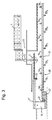
- the log load 1, the trunk reducer 3 and the debarker 5 are conventional Wise designed.
- the logs are lifted with a gantry crane or abandoned directly from a truck and conveyed to the trunk reducer 3, the heavily woody, i.e. strongly conical trunks reduced to a size to be processed. Then the if necessary, reduced tree trunk in the debarker 5.
- the tree trunk is now aligned accordingly, it is conveyed via a suitable conveyor (not shown) to the vertical log band saw 13, which is divided into two tree halves 15a and 15b by a vertical cut essentially through the center.
- the section plane is indicated with B 1 . It can be seen that the area 11 comes to rest exclusively in the half 15a.
- a tilting device is combined, which rotates the trunk quarter 23a or 23b by 90 °, so that the cutting surface of the last cut is tilted horizontally and the other, perpendicular surface of the trunk quarter into the vertical, so that it passes through the Diagonal conveyor is brought to rest against the stop of the subsequent band saw.
- Suitable guiding means are provided in the area of the band saw TA i and TB i , which ensure that the respective band saw cuts a screed of constant thickness from the trunk quarter against the stop.
- the thickness of the screed is determined by the distance of the saw blade from the stop of the saw.
- the separated planks fall to the right and left of the conveyor lane 31 by slipping onto conveyor belts (not shown) running parallel to the conveyor lane 31 and are removed.
- the stops of the band saws are equipped with a suitable drive for adjusting the cutting thickness.
- the illustrated embodiment can be modified in various ways.
- the diagonal conveyor between the sawing stations TA i and TB i can be replaced by the combination of a longitudinal conveyor and a cross conveyor in the conveyor alley 31.
- the band saws TA i and TB i can also be provided that the cutting plane of the individual band saws in the conveying direction is increasingly closer to the center of the conveyor line 31 lies, so that already by tilting between the individual saws the trunk quarter is brought into the correct position for processing by the next saw.
- this requires the individual setting of the cutting planes of the band saws to the respective trunk diameter or prior processing of the trunk or the trunk quarters to standard dimensions.
Landscapes
- Life Sciences & Earth Sciences (AREA)
- Engineering & Computer Science (AREA)
- Mechanical Engineering (AREA)
- Wood Science & Technology (AREA)
- Forests & Forestry (AREA)
- Sawing (AREA)
Applications Claiming Priority (2)
| Application Number | Priority Date | Filing Date | Title |
|---|---|---|---|
| DE1999113566 DE19913566A1 (de) | 1999-03-25 | 1999-03-25 | Vorrichtung zum Zerlegen von Baumstämmen in einem Schnitt mit mehreren nicht parallelen Schnittebenen, insbesondere in einem Quartierschnitt |
| DE19913566 | 1999-03-25 |
Publications (2)
| Publication Number | Publication Date |
|---|---|
| EP1038643A2 true EP1038643A2 (fr) | 2000-09-27 |
| EP1038643A3 EP1038643A3 (fr) | 2001-06-06 |
Family
ID=7902374
Family Applications (1)
| Application Number | Title | Priority Date | Filing Date |
|---|---|---|---|
| EP00106273A Withdrawn EP1038643A3 (fr) | 1999-03-25 | 2000-03-22 | Ensemble de scies à ruban pour la découpe de troncs d'arbres, en particulier des quarts d'arbres |
Country Status (2)
| Country | Link |
|---|---|
| EP (1) | EP1038643A3 (fr) |
| DE (1) | DE19913566A1 (fr) |
Cited By (1)
| Publication number | Priority date | Publication date | Assignee | Title |
|---|---|---|---|---|
| EP1283312A1 (fr) * | 2001-08-09 | 2003-02-12 | Stefan Hellberg | Lambris pour revêtir des surfaces verticales |
Families Citing this family (4)
| Publication number | Priority date | Publication date | Assignee | Title |
|---|---|---|---|---|
| DE102007037039A1 (de) | 2007-08-06 | 2009-02-12 | Christian Obermeier | Verfahren zur Gewinnung hochwertigen Brettmaterials aus Rundholz |
| DE102009016357A1 (de) | 2009-04-07 | 2011-02-17 | Georg Burger | Verfahren und Vorrichtung zum Zerlegen von Baumstämmen |
| DE102009021690A1 (de) | 2009-05-18 | 2012-01-12 | Georg Burger | Anlage und Verfahren zum Zerlegen von Baumstämmen |
| CN112008822B (zh) * | 2020-08-26 | 2022-03-18 | 广西壮族自治区林业科学研究院 | 一种高出材率木材物理力学试材制作方法 |
Family Cites Families (8)
| Publication number | Priority date | Publication date | Assignee | Title |
|---|---|---|---|---|
| BE687283A (fr) * | 1965-09-24 | 1967-03-23 | ||
| US3457978A (en) * | 1966-11-07 | 1969-07-29 | Mo Och Domsjoe Ab | Method and apparatus for cutting logs into lumber and recovering the byproducts |
| US3552457A (en) * | 1968-05-29 | 1971-01-05 | Mac Millan Bloedel Ltd | Log break-down method and apparatus |
| DE2720139A1 (de) * | 1977-05-05 | 1978-11-16 | Elmar Dr Ing Schulte | Blocksaege und verfahren zum aufteilen von rohstaemmen |
| AT382549B (de) * | 1985-09-30 | 1987-03-10 | Wolf Johann Gmbh Kg | Verfahren und vorrichtung zum besaeumen von baumstaemmen |
| CA1301371C (fr) * | 1988-08-23 | 1992-05-19 | Jan Erik Aune | Dispositif de classement automatique des grumes |
| SE9200923L (sv) * | 1991-03-27 | 1992-09-28 | Risto Heikki Pitkaenen | Foerfarande foer kvalitetssaagning av saagstockar |
| FR2709263B1 (fr) * | 1993-08-27 | 1995-11-10 | Cirad | Ligne et procédé de sciage de bois sur quartier. |
-
1999
- 1999-03-25 DE DE1999113566 patent/DE19913566A1/de not_active Withdrawn
-
2000
- 2000-03-22 EP EP00106273A patent/EP1038643A3/fr not_active Withdrawn
Cited By (1)
| Publication number | Priority date | Publication date | Assignee | Title |
|---|---|---|---|---|
| EP1283312A1 (fr) * | 2001-08-09 | 2003-02-12 | Stefan Hellberg | Lambris pour revêtir des surfaces verticales |
Also Published As
| Publication number | Publication date |
|---|---|
| DE19913566A1 (de) | 2000-10-05 |
| EP1038643A3 (fr) | 2001-06-06 |
Similar Documents
| Publication | Publication Date | Title |
|---|---|---|
| DE3343953A1 (de) | Verfahren zur bearbeitung gekruemmter staemme | |
| WO1987005555A1 (fr) | Procede et dispositif pour introduire des troncs d'arbre dans une machine de traitement | |
| DE3720169A1 (de) | Saegevorrichtung | |
| DE3244393C1 (de) | Verfahren zum Herstellen von allseitig bearbeiteten Holzerzeugnissen sowie Vorrichtung zur Durchfuehrung des Verfahrens | |
| DE2754502A1 (de) | Vorrichtung zum axialen transportieren von holzstuecken durch eine bearbeitungsstation | |
| EP0261568B1 (fr) | Machine à travailler le bois | |
| EP0963822B1 (fr) | Dispositif et procédé pour le sciage des troncs d'arbres | |
| DE69225078T2 (de) | Vorrichtung und verfahren zum sägen von kantholz | |
| DE19913566A1 (de) | Vorrichtung zum Zerlegen von Baumstämmen in einem Schnitt mit mehreren nicht parallelen Schnittebenen, insbesondere in einem Quartierschnitt | |
| DE4212432A1 (de) | Vorrichtung zum spanlosen Abschneiden von Holzlamellen von einem Kantholz | |
| EP4100222A1 (fr) | Installation de sciage et procédé de sciage d'un matériau de sciage | |
| DE4337682C1 (de) | Verfahren und Vorrichtung zum Zerlegen eines Baumstammes | |
| DE102020103192B4 (de) | Sägeanlage und Verfahren zum Sägen eines Sägeguts | |
| WO2004067238A1 (fr) | Procede et ligne d'usinage permettant de decouper des troncs d'arbres | |
| EP1046480B1 (fr) | Dispositif pour la découpe de troncs d'arbres utlisant des scies circulaires montées à angle droit et station de sciage associée | |
| DE3244450C2 (fr) | ||
| DE3317307C2 (fr) | ||
| EP1365899A2 (fr) | Procede et dispositif pour decouper des bois ronds courbes dans un plan afin d'obtenir des produits ligneux | |
| EP3036074B1 (fr) | Dispositif permettant de découper des planches ou des poutres | |
| DE102005024581B4 (de) | Vorrichtung zum Ausrichten von Holzerzeugnissen | |
| DE202025107251U1 (de) | Sägewerkanlage zum Zerlegen von Rundhölzern | |
| DE19927742C1 (de) | Vorrichtung zum Zerlegen von Baumstämmen in einem Quartierschnitt und zugehörige Sägestation | |
| DE3820148C2 (fr) | ||
| DE102004062373B4 (de) | Verfahren und Vorrichtung zum Fördern von Baumstämmen | |
| DE19535044B4 (de) | Vorrichtung zum Zerlegen der aus einer Sägemaschine kommenden, aus Blöcken geschnittenen Schnittholzbündel |
Legal Events
| Date | Code | Title | Description |
|---|---|---|---|
| PUAI | Public reference made under article 153(3) epc to a published international application that has entered the european phase |
Free format text: ORIGINAL CODE: 0009012 |
|
| AK | Designated contracting states |
Kind code of ref document: A2 Designated state(s): AT BE CH CY DE DK ES FI FR GB GR IE IT LI LU MC NL PT SE |
|
| AX | Request for extension of the european patent |
Free format text: AL;LT;LV;MK;RO;SI |
|
| PUAL | Search report despatched |
Free format text: ORIGINAL CODE: 0009013 |
|
| AK | Designated contracting states |
Kind code of ref document: A3 Designated state(s): AT BE CH CY DE DK ES FI FR GB GR IE IT LI LU MC NL PT SE |
|
| AX | Request for extension of the european patent |
Free format text: AL;LT;LV;MK;RO;SI |
|
| 17P | Request for examination filed |
Effective date: 20010816 |
|
| AKX | Designation fees paid |
Free format text: AT BE CH CY DE DK ES FI FR GB GR IE IT LI LU MC NL PT SE |
|
| AXX | Extension fees paid |
Free format text: LT PAYMENT 20011206;LV PAYMENT 20011206;RO PAYMENT 20011206 |
|
| 17Q | First examination report despatched |
Effective date: 20020304 |
|
| GRAP | Despatch of communication of intention to grant a patent |
Free format text: ORIGINAL CODE: EPIDOSNIGR1 |
|
| GRAP | Despatch of communication of intention to grant a patent |
Free format text: ORIGINAL CODE: EPIDOSNIGR1 |
|
| STAA | Information on the status of an ep patent application or granted ep patent |
Free format text: STATUS: THE APPLICATION IS DEEMED TO BE WITHDRAWN |
|
| 18D | Application deemed to be withdrawn |
Effective date: 20040330 |