EP1038652B1 - Vakuum und druckdichte Kühlventilatorvorrichtung für Warmumformmaschinen - Google Patents
Vakuum und druckdichte Kühlventilatorvorrichtung für Warmumformmaschinen Download PDFInfo
- Publication number
- EP1038652B1 EP1038652B1 EP00101424A EP00101424A EP1038652B1 EP 1038652 B1 EP1038652 B1 EP 1038652B1 EP 00101424 A EP00101424 A EP 00101424A EP 00101424 A EP00101424 A EP 00101424A EP 1038652 B1 EP1038652 B1 EP 1038652B1
- Authority
- EP
- European Patent Office
- Prior art keywords
- thermoforming station
- fan
- bell
- thermoforming
- inlet portion
- Prior art date
- Legal status (The legal status is an assumption and is not a legal conclusion. Google has not performed a legal analysis and makes no representation as to the accuracy of the status listed.)
- Expired - Lifetime
Links
- 238000003856 thermoforming Methods 0.000 title claims abstract description 33
- 238000001816 cooling Methods 0.000 title claims abstract description 19
- 238000007789 sealing Methods 0.000 claims description 6
- 239000000463 material Substances 0.000 description 10
- 238000000034 method Methods 0.000 description 4
- 238000000465 moulding Methods 0.000 description 3
- 238000006073 displacement reaction Methods 0.000 description 2
- 238000004873 anchoring Methods 0.000 description 1
- 210000004027 cell Anatomy 0.000 description 1
- 210000003850 cellular structure Anatomy 0.000 description 1
- 230000001419 dependent effect Effects 0.000 description 1
- 238000012986 modification Methods 0.000 description 1
- 230000004048 modification Effects 0.000 description 1
Images

Classifications
-
- B—PERFORMING OPERATIONS; TRANSPORTING
- B29—WORKING OF PLASTICS; WORKING OF SUBSTANCES IN A PLASTIC STATE IN GENERAL
- B29C—SHAPING OR JOINING OF PLASTICS; SHAPING OF MATERIAL IN A PLASTIC STATE, NOT OTHERWISE PROVIDED FOR; AFTER-TREATMENT OF THE SHAPED PRODUCTS, e.g. REPAIRING
- B29C51/00—Shaping by thermoforming, i.e. shaping sheets or sheet like preforms after heating, e.g. shaping sheets in matched moulds or by deep-drawing; Apparatus therefor
- B29C51/26—Component parts, details or accessories; Auxiliary operations
- B29C51/42—Heating or cooling
- B29C51/427—Cooling of the material with a fluid blast
-
- B—PERFORMING OPERATIONS; TRANSPORTING
- B29—WORKING OF PLASTICS; WORKING OF SUBSTANCES IN A PLASTIC STATE IN GENERAL
- B29C—SHAPING OR JOINING OF PLASTICS; SHAPING OF MATERIAL IN A PLASTIC STATE, NOT OTHERWISE PROVIDED FOR; AFTER-TREATMENT OF THE SHAPED PRODUCTS, e.g. REPAIRING
- B29C2791/00—Shaping characteristics in general
- B29C2791/004—Shaping under special conditions
- B29C2791/006—Using vacuum
-
- B—PERFORMING OPERATIONS; TRANSPORTING
- B29—WORKING OF PLASTICS; WORKING OF SUBSTANCES IN A PLASTIC STATE IN GENERAL
- B29C—SHAPING OR JOINING OF PLASTICS; SHAPING OF MATERIAL IN A PLASTIC STATE, NOT OTHERWISE PROVIDED FOR; AFTER-TREATMENT OF THE SHAPED PRODUCTS, e.g. REPAIRING
- B29C51/00—Shaping by thermoforming, i.e. shaping sheets or sheet like preforms after heating, e.g. shaping sheets in matched moulds or by deep-drawing; Apparatus therefor
- B29C51/10—Forming by pressure difference, e.g. vacuum
-
- Y—GENERAL TAGGING OF NEW TECHNOLOGICAL DEVELOPMENTS; GENERAL TAGGING OF CROSS-SECTIONAL TECHNOLOGIES SPANNING OVER SEVERAL SECTIONS OF THE IPC; TECHNICAL SUBJECTS COVERED BY FORMER USPC CROSS-REFERENCE ART COLLECTIONS [XRACs] AND DIGESTS
- Y10—TECHNICAL SUBJECTS COVERED BY FORMER USPC
- Y10S—TECHNICAL SUBJECTS COVERED BY FORMER USPC CROSS-REFERENCE ART COLLECTIONS [XRACs] AND DIGESTS
- Y10S425/00—Plastic article or earthenware shaping or treating: apparatus
- Y10S425/812—Venting
Definitions
- the present invention relates to a thermoforming station with a bell provided with a cover, which can be opened for fast evacuation of the air from the bell, as described in the introductory part of the claim 1.
- thermoforming stations the invention is related to are conventionally provided for molding a sheet-like (or plate or coil-like) plastic material by drawing this material inside a bell assembly arranged at a position opposite to a mold bearing assembly, so as to be closed on the latter.
- thermoforming station the sheet-like plastic material is brought at first to its plasticizing temperature and then it is locked, in a molding position, by closing the mentioned bell assembly against a perimetrical edge of the plastic material.
- the inside of the bell assembly is evacuated to draw the plastic material into the bell assembly, in order to provide said plastic material with a pre-stretched ball configuration.
- the plastic material as molded is allowed to cool, the bell assembly being constantly closed on the mold to hold the plastic material on the mold itself.
- the cooling step represents the most critical processing step since the outer surface of the molded article must be evenly cooled. In fact, if the outer surface would not be properly evenly cooled, it could retain inner stresses which could deform the molded article which would be rejected.
- the cooling step represents the longest operating step of the thermoforming process and, in order to increase the thermoforming process yield it would be indispensable to make the cooling stage as short as possible.
- thermoforming station in order to accelerate the cooling step of the forming process the inventor of the present invention has provided, in an earlier patent application under the priority date of 3 April 1998, and extended in the European patent application EP-0947307, published 6 October 1999, that a thermoforming station be realised provided with a bell comprising a cover, which can be opened for fast evacuation of the air from the bell. As the cover is lifted, a very large air passage opening is formed, which permits fast exchange of the air, and thus fast cooling. Using fans, cooling air is blown into the opened bell.
- a thermoforming station as described in the introductory part of claim 1 is also known from US-A-3 713 765.
- the state of the art furthermore describes devices for sealing the opening of a fan (e.g. the US-A-3396904 or the EP-0255663A2) or for realising a thermoforming station, which can be opened for the cooling phase (e.g. the EP-0365951A2; the first mentioned solution is limited to the application fo a diaphragm closing element on the fan entrance.
- a fan e.g. the US-A-3396904 or the EP-0255663A2
- thermoforming station e.g. the EP-0365951A2
- the first mentioned solution is limited to the application fo a diaphragm closing element on the fan entrance.
- the main object of the present invention is to provide ventilating means specifically designed for aiding air to easily circulate inside the mentioned thermoforming stations.
- thermoforming station according to Claim 1.
- thermoforming station The provision, on the inventive device, of a shutter element arranged outside the thermoforming station, provides the advantage that an air jet can be easily directed and oriented in the thermoforming station.
- said outer shutter element will facilitate the assembling operations, and will reduce the operating noise (since said shutter element will break the air flow) while reducing the size of the device, to allow a desired number of ventilating devices to be easily arranged about the bell assembly.
- the device according to the invention moreover, provides the additional advantage of easily shutting off or closing the ventilating device, and this by the mentioned shutter element operating with a return force directed in the direction of the vacuum formed inside the bell assembly.
- thermoforming station will facilitate the closing of the shutter element, while properly holding it in this closing position.
- the bell assembly evacuation time as well as the cooling time will be reduced to a minimum.
- the cooling time can be reduced, owing to the inventive device, to total time less than 20 seconds, thereby easily overcoming a threshold of 120 cycles/hours as conventionally provided in processes designed for making domestic refrigerators, cells and counter-doors.
- the inventive device further provides a sealing action against a possible air overpressure generated in the thermoforming station for aiding the thermoforming process.
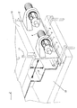
- the cooling ventilating device of the invention has been generally indicated by the reference number 1 in Figure 1.
- Said device comprises a scroll body 2, on the front of which the air outlet 3 has been provided.
- An electric motor 4 for driving the ventilating fan has been moreover provided.
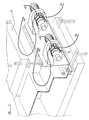
- the ventilating device 1 is provided with a shutter cover 6, which can be driven from an open position (shown by a solid line in Figures 1 and 3) to a closed position ( Figure 2 and dashed in Figure 1).
- the shutter cover or element 6 the shape and size of which have been specifically designed for fully covering the air inlet 5 to the ventilating device 1, is slidably mounted on guides 7, which are in turn mounted between a support 8, on the body side 2 of the ventilating device 1, and a corresponding support 9 opposite to the mentioned support 8.
- the support 9 supports moreover a piston 10-cylinder 11 assembly, which comprises an element 12 for anchoring the piston 10 to the shutter element 6.
- a gasket 13 is moreover provided for air sealing the shutter element 6 on the support 8 (and, accordingly, on the ventilating device body 2, at the level of the air inlet 5 of the latter).
- the above disclosed ventilating device is coupled on the thermoforming station shown in Figures 2 and 3, to form an integrating part of the latter.
- thermoforming station comprises, in particular, a bell assembly 15, having a cover 16 which can be raised and lowered along guiding pins 17 through driving means (not shown).
- the shutter element 6 is brought to its closing position against the air inlet 5 by a displacement in the direction of the arrow F1 of Figure 2.
- This displacement is driven by the piston 10 and is aided by the vacuum formed inside the thermoforming station for thermoforming the sheet material 18 on the mold pattern 19.
- the generated vacuum moreover, will facilitate the abutment and holding of the shutter element 6 on the edge of the air inlet 5 thereby providing an efficient sealing of the latter.
- the cooling ventilating device 1 is driven to cause cooling air to circulate in the direction of the arrows F3 and F4 of Figures 1 and 3.
Landscapes
- Engineering & Computer Science (AREA)
- Mechanical Engineering (AREA)
- Blow-Moulding Or Thermoforming Of Plastics Or The Like (AREA)
- Structures Of Non-Positive Displacement Pumps (AREA)
- Cold Air Circulating Systems And Constructional Details In Refrigerators (AREA)
- Press Drives And Press Lines (AREA)
- Encapsulation Of And Coatings For Semiconductor Or Solid State Devices (AREA)
- Furnace Details (AREA)
Claims (7)
- Warmumformungsstation mit einer Glocke (15), die mit einer Abdeckung (16) versehen ist, welche für eine schnelle Evakuierung der Luft aus der Glocke (15) geöffnet werden kann, um ein schnelles Abkühlen des geformten Gegenstandes zu erlangen, und mit mindestens einer Gebläseanordnung (1), die außerhalb der Glocke (15) angeordnet ist, wobei die Gebläseanordnung einen Gebläsekörper mit einem Lufteinlassabschnitt (5) aufweist,
dadurch gekennzeichnet, dass
die mindestens eine Gebläseanordnung (1) fest an der Glocke (15) befestigt ist, und der Einlassabschnitt mit einem Mittel (6) zum Verschließen des Einlassabschnittes (5) versehen ist. - Warmumformungsstation nach Anspruch 1,
dadurch gekennzeichnet, dass
das Mittel (6) zum Verschließen des Einlassabschnitts (5) aus einer Verschlussabdeckung (6) besteht, die zwischen einer Position, in der das Gebläse offen ist, und einer, in der das Gebläse geschlossen ist, bewegt werden kann und die abgedichtet werden kann, um Vakuum und Druck aufrechtzuerhalten. - Warmumformungsstation nach Anspruch 2,
dadurch gekennzeichnet, dass
Abstützungsführungen (7) für die bewegliche Verschlussabdeckung (6) vorgesehen sind, die sich in Richtung auf die Lufteinlassöffnung (5) des Gebläses und von dieser weg bewegen kann. - Warmumformungsstation nach Anspruch 3,
dadurch gekennzeichnet, dass
Abstützungselemente (6, 9) vorgesehen sind, die die Führungen (7) an dem Gebläsekörper (2) aufnehmen. - Warmumformungsstation nach Anspruch 3 oder 4,
dadurch gekennzeichnet, dass
eine Vorrichtung mit einem Zylinder (11) und einem Kolben (10) vorgesehen ist, um die Verschlussabdeckung (6) zu bewegen. - Warmumformungsstation nach Anspruch 5,
dadurch gekennzeichnet, dass
eine Dichtung (13) an dem Rand der Abdichtungsabdeckung (5) vorgesehen ist, die an der Einlassöffnungsplatte (8) anliegt. - Warmumformungsstation nach Anspruch 1,
dadurch gekennzeichnet, dass
zwei oder mehr Gebläseanordnungen vorgesehen sind, um die Warmumformungsstation unter Umgebungsdruck zu halten, wobei eine jede mit einem Mittel zum Unterbrechen der Luftströmung versehen ist, das an dem Lufteinlassabschnitt des Gebläsekörpers angeordnet ist, wobei die Mittel gleichzeitig bewegt werden können.
Applications Claiming Priority (2)
| Application Number | Priority Date | Filing Date | Title |
|---|---|---|---|
| IT1999MI000638A IT1312234B1 (it) | 1999-03-26 | 1999-03-26 | Dispositivo ventilatore a tenuta di vuoto e pressione, in particolareper stazioni di termoformatura, e stazione di termoformatura |
| ITMI990638 | 1999-03-26 |
Publications (3)
| Publication Number | Publication Date |
|---|---|
| EP1038652A2 EP1038652A2 (de) | 2000-09-27 |
| EP1038652A3 EP1038652A3 (de) | 2003-01-15 |
| EP1038652B1 true EP1038652B1 (de) | 2006-09-06 |
Family
ID=11382482
Family Applications (1)
| Application Number | Title | Priority Date | Filing Date |
|---|---|---|---|
| EP00101424A Expired - Lifetime EP1038652B1 (de) | 1999-03-26 | 2000-01-25 | Vakuum und druckdichte Kühlventilatorvorrichtung für Warmumformmaschinen |
Country Status (8)
| Country | Link |
|---|---|
| US (1) | US6454556B1 (de) |
| EP (1) | EP1038652B1 (de) |
| AT (1) | ATE338626T1 (de) |
| BR (1) | BR0002047A (de) |
| CA (1) | CA2298726A1 (de) |
| DE (1) | DE60030501T2 (de) |
| ES (1) | ES2272207T3 (de) |
| IT (1) | IT1312234B1 (de) |
Families Citing this family (4)
| Publication number | Priority date | Publication date | Assignee | Title |
|---|---|---|---|---|
| US7708932B2 (en) * | 2006-10-02 | 2010-05-04 | Ford Global Technologies, Llc | Chilled air pressure box for thermoforming a plastic sheet and a method of thermoforming the same |
| US7963749B1 (en) * | 2006-11-25 | 2011-06-21 | Climatecraft Technologies, Inc. | Fan with variable motor speed and disk type unloading device |
| CN113103648A (zh) * | 2021-04-27 | 2021-07-13 | 金溪县金港实业有限公司 | 一种体育保护垫生产用冲压黏合设备 |
| CN118664878B (zh) * | 2024-07-20 | 2025-11-28 | 浙江鼎富橡塑科技有限公司 | 高密封防尘罩吹塑装置 |
Family Cites Families (11)
| Publication number | Priority date | Publication date | Assignee | Title |
|---|---|---|---|---|
| US2098144A (en) * | 1936-07-20 | 1937-11-02 | Hanus John | Air controlling device for blowers |
| US3396904A (en) * | 1967-03-27 | 1968-08-13 | Jan Air Inc | Adjustable air inlet closure |
| US3625629A (en) * | 1970-06-04 | 1971-12-07 | M K M Corp | Proportional blower |
| US3713765A (en) * | 1970-10-22 | 1973-01-30 | D Rise | Differential pressure thermoforming apparatus for forming large articles such as trailer bodies and boats |
| ES2021308B3 (es) * | 1986-08-04 | 1991-11-01 | Siemens Ag | Camara de aire para el sistema de aeracion de un vehiculo motorizado |
| FR2638117B1 (fr) * | 1988-10-24 | 1994-07-29 | Anhydride Carbonique Ind | Procede et dispositif de refroidissement de pieces obtenues par thermoformage |
| US5217563A (en) * | 1988-12-01 | 1993-06-08 | Bayer Aktiengesellschaft | Apparatus for producing a deep-drawn formed plastic piece |
| US5161941A (en) * | 1990-08-28 | 1992-11-10 | Sinko Kogyo, Co, Ltd. | Actuator assembly for controlling inlet air flow to centrifugal fans |
| DE4141362C2 (de) * | 1991-12-14 | 2002-10-24 | Motoren Ventilatoren Gmbh | Radialgebläse mit Drosselvorrichtung |
| US5620715A (en) * | 1994-02-10 | 1997-04-15 | Penda Corporation | Thermoforming machine with controlled cooling station |
| IT1299023B1 (it) * | 1998-04-03 | 2000-02-07 | Rigo Group S R L | Stazione di termoformatura con sistema di raffreddamento rapido della stampata e procedimento di termoformatura realizzato con questa |
-
1999
- 1999-03-26 IT IT1999MI000638A patent/IT1312234B1/it active
-
2000
- 2000-01-19 US US09/487,152 patent/US6454556B1/en not_active Expired - Fee Related
- 2000-01-25 AT AT00101424T patent/ATE338626T1/de not_active IP Right Cessation
- 2000-01-25 ES ES00101424T patent/ES2272207T3/es not_active Expired - Lifetime
- 2000-01-25 EP EP00101424A patent/EP1038652B1/de not_active Expired - Lifetime
- 2000-01-25 DE DE60030501T patent/DE60030501T2/de not_active Expired - Fee Related
- 2000-02-16 CA CA002298726A patent/CA2298726A1/en not_active Abandoned
- 2000-02-29 BR BR0002047-8A patent/BR0002047A/pt not_active Application Discontinuation
Also Published As
| Publication number | Publication date |
|---|---|
| EP1038652A2 (de) | 2000-09-27 |
| CA2298726A1 (en) | 2000-09-26 |
| ES2272207T3 (es) | 2007-05-01 |
| ITMI990638A1 (it) | 2000-09-26 |
| EP1038652A3 (de) | 2003-01-15 |
| DE60030501D1 (de) | 2006-10-19 |
| BR0002047A (pt) | 2000-11-14 |
| DE60030501T2 (de) | 2007-04-12 |
| IT1312234B1 (it) | 2002-04-09 |
| ATE338626T1 (de) | 2006-09-15 |
| US6454556B1 (en) | 2002-09-24 |
Similar Documents
| Publication | Publication Date | Title |
|---|---|---|
| US7600358B2 (en) | Method and packaging machine for packaging a product arranged in a tray | |
| EP0947307B1 (de) | Warmformstation und Verfahren mit einem Schnellkühlsystem zum Kühlen von warmgeformten Gegenständen | |
| JP2004538183A (ja) | 高耐衝撃性透明無歪みポリマー材料を成形する方法および装置 | |
| EP1038652B1 (de) | Vakuum und druckdichte Kühlventilatorvorrichtung für Warmumformmaschinen | |
| US5720992A (en) | Movable extractor plate assembly for rapidly removing articles from a thermoforming apparatus | |
| JPS60180816A (ja) | 熱可塑性のプラスチツクから深絞り部分を製造する装置及びこの装置で実施する方法 | |
| JP2003236840A (ja) | タイヤ加硫装置 | |
| CN113844012A (zh) | 一种真空吸塑成型模具及吸塑工艺 | |
| US4447200A (en) | Apparatus for molding skylights | |
| CN212764738U (zh) | 一种盒盖吸塑装置 | |
| JP3343154B2 (ja) | 成形装置 | |
| CN218430181U (zh) | 一种汽车喇叭罩生产用便于卸料的模具 | |
| JPH09183124A (ja) | 真空排気機構を有するタイヤ加硫装置とタイヤ加硫方法 | |
| CN116985426A (zh) | 一种复合材料双袋热隔膜预成型设备及其方法 | |
| JP2005144968A (ja) | 金型装置 | |
| CN221624752U (zh) | 一种仓储式冷却存储设备 | |
| JPH11138592A (ja) | 加飾成形用金型の雌型 | |
| CN224034879U (zh) | 头模气动控制气密性检测装置 | |
| JP2002264131A (ja) | 成形体の形状修正方法および装置 | |
| CN218876205U (zh) | 一种塑料注塑用风冷结构 | |
| CN216544408U (zh) | 一种快速冷却的齿条加工用注射模具 | |
| CN113448187B (zh) | 一种复合半导体薄膜材料光刻胶去除装置 | |
| CN220923126U (zh) | 一种汽车橡胶件注塑成型装置 | |
| CN218803965U (zh) | 一种快速冷却的热成型设备 | |
| CN120422450A (zh) | 一种用于冰箱门框生产的吸塑设备 |
Legal Events
| Date | Code | Title | Description |
|---|---|---|---|
| PUAI | Public reference made under article 153(3) epc to a published international application that has entered the european phase |
Free format text: ORIGINAL CODE: 0009012 |
|
| AK | Designated contracting states |
Kind code of ref document: A2 Designated state(s): AT BE CH CY DE DK ES FI FR GB GR IE IT LI LU MC NL PT SE |
|
| AX | Request for extension of the european patent |
Free format text: AL;LT;LV;MK;RO;SI |
|
| RAP1 | Party data changed (applicant data changed or rights of an application transferred) |
Owner name: RIGO-GAM S.A. |
|
| PUAL | Search report despatched |
Free format text: ORIGINAL CODE: 0009013 |
|
| AK | Designated contracting states |
Kind code of ref document: A3 Designated state(s): AT BE CH CY DE DK ES FI FR GB GR IE IT LI LU MC NL PT SE |
|
| AX | Request for extension of the european patent |
Free format text: AL;LT;LV;MK;RO;SI |
|
| RIC1 | Information provided on ipc code assigned before grant |
Free format text: 7B 29C 51/42 A, 7F 04D 29/42 B |
|
| 17P | Request for examination filed |
Effective date: 20030703 |
|
| AKX | Designation fees paid |
Designated state(s): AT BE CH CY DE DK ES FI FR GB GR IE IT LI LU MC NL PT SE |
|
| 17Q | First examination report despatched |
Effective date: 20040407 |
|
| GRAP | Despatch of communication of intention to grant a patent |
Free format text: ORIGINAL CODE: EPIDOSNIGR1 |
|
| GRAS | Grant fee paid |
Free format text: ORIGINAL CODE: EPIDOSNIGR3 |
|
| GRAA | (expected) grant |
Free format text: ORIGINAL CODE: 0009210 |
|
| AK | Designated contracting states |
Kind code of ref document: B1 Designated state(s): AT BE CH CY DE DK ES FI FR GB GR IE IT LI LU MC NL PT SE |
|
| PG25 | Lapsed in a contracting state [announced via postgrant information from national office to epo] |
Ref country code: IT Free format text: LAPSE BECAUSE OF FAILURE TO SUBMIT A TRANSLATION OF THE DESCRIPTION OR TO PAY THE FEE WITHIN THE PRE;WARNING: LAPSES OF ITALIAN PATENTS WITH EFFECTIVE DATE BEFORE 2007 MAY HAVE OCCURRED AT ANY TIME BEFORE 2007. THE CORRECT EFFECTIVE DATE MAY BE DIFFERENT FROM THE ONE RECORDED.SCRIBED TIME-LIMIT Effective date: 20060906 Ref country code: AT Free format text: LAPSE BECAUSE OF FAILURE TO SUBMIT A TRANSLATION OF THE DESCRIPTION OR TO PAY THE FEE WITHIN THE PRESCRIBED TIME-LIMIT Effective date: 20060906 Ref country code: LI Free format text: LAPSE BECAUSE OF FAILURE TO SUBMIT A TRANSLATION OF THE DESCRIPTION OR TO PAY THE FEE WITHIN THE PRESCRIBED TIME-LIMIT Effective date: 20060906 Ref country code: NL Free format text: LAPSE BECAUSE OF FAILURE TO SUBMIT A TRANSLATION OF THE DESCRIPTION OR TO PAY THE FEE WITHIN THE PRESCRIBED TIME-LIMIT Effective date: 20060906 Ref country code: FI Free format text: LAPSE BECAUSE OF FAILURE TO SUBMIT A TRANSLATION OF THE DESCRIPTION OR TO PAY THE FEE WITHIN THE PRESCRIBED TIME-LIMIT Effective date: 20060906 Ref country code: BE Free format text: LAPSE BECAUSE OF FAILURE TO SUBMIT A TRANSLATION OF THE DESCRIPTION OR TO PAY THE FEE WITHIN THE PRESCRIBED TIME-LIMIT Effective date: 20060906 Ref country code: CH Free format text: LAPSE BECAUSE OF FAILURE TO SUBMIT A TRANSLATION OF THE DESCRIPTION OR TO PAY THE FEE WITHIN THE PRESCRIBED TIME-LIMIT Effective date: 20060906 |
|
| REG | Reference to a national code |
Ref country code: GB Ref legal event code: FG4D |
|
| REG | Reference to a national code |
Ref country code: CH Ref legal event code: EP |
|
| REG | Reference to a national code |
Ref country code: IE Ref legal event code: FG4D |
|
| REF | Corresponds to: |
Ref document number: 60030501 Country of ref document: DE Date of ref document: 20061019 Kind code of ref document: P |
|
| PG25 | Lapsed in a contracting state [announced via postgrant information from national office to epo] |
Ref country code: SE Free format text: LAPSE BECAUSE OF FAILURE TO SUBMIT A TRANSLATION OF THE DESCRIPTION OR TO PAY THE FEE WITHIN THE PRESCRIBED TIME-LIMIT Effective date: 20061206 Ref country code: DK Free format text: LAPSE BECAUSE OF FAILURE TO SUBMIT A TRANSLATION OF THE DESCRIPTION OR TO PAY THE FEE WITHIN THE PRESCRIBED TIME-LIMIT Effective date: 20061206 |
|
| PG25 | Lapsed in a contracting state [announced via postgrant information from national office to epo] |
Ref country code: IE Free format text: LAPSE BECAUSE OF NON-PAYMENT OF DUE FEES Effective date: 20070125 |
|
| PG25 | Lapsed in a contracting state [announced via postgrant information from national office to epo] |
Ref country code: MC Free format text: LAPSE BECAUSE OF NON-PAYMENT OF DUE FEES Effective date: 20070131 |
|
| PG25 | Lapsed in a contracting state [announced via postgrant information from national office to epo] |
Ref country code: PT Free format text: LAPSE BECAUSE OF FAILURE TO SUBMIT A TRANSLATION OF THE DESCRIPTION OR TO PAY THE FEE WITHIN THE PRESCRIBED TIME-LIMIT Effective date: 20070219 |
|
| NLV1 | Nl: lapsed or annulled due to failure to fulfill the requirements of art. 29p and 29m of the patents act | ||
| ET | Fr: translation filed | ||
| REG | Reference to a national code |
Ref country code: CH Ref legal event code: PL |
|
| REG | Reference to a national code |
Ref country code: ES Ref legal event code: FG2A Ref document number: 2272207 Country of ref document: ES Kind code of ref document: T3 |
|
| PLBE | No opposition filed within time limit |
Free format text: ORIGINAL CODE: 0009261 |
|
| STAA | Information on the status of an ep patent application or granted ep patent |
Free format text: STATUS: NO OPPOSITION FILED WITHIN TIME LIMIT |
|
| 26N | No opposition filed |
Effective date: 20070607 |
|
| REG | Reference to a national code |
Ref country code: ES Ref legal event code: FD2A Effective date: 20070126 |
|
| PG25 | Lapsed in a contracting state [announced via postgrant information from national office to epo] |
Ref country code: GR Free format text: LAPSE BECAUSE OF FAILURE TO SUBMIT A TRANSLATION OF THE DESCRIPTION OR TO PAY THE FEE WITHIN THE PRESCRIBED TIME-LIMIT Effective date: 20061207 |
|
| PG25 | Lapsed in a contracting state [announced via postgrant information from national office to epo] |
Ref country code: ES Free format text: LAPSE BECAUSE OF NON-PAYMENT OF DUE FEES Effective date: 20070126 |
|
| PGFP | Annual fee paid to national office [announced via postgrant information from national office to epo] |
Ref country code: FR Payment date: 20081203 Year of fee payment: 10 |
|
| PGFP | Annual fee paid to national office [announced via postgrant information from national office to epo] |
Ref country code: GB Payment date: 20090121 Year of fee payment: 10 |
|
| PG25 | Lapsed in a contracting state [announced via postgrant information from national office to epo] |
Ref country code: CY Free format text: LAPSE BECAUSE OF FAILURE TO SUBMIT A TRANSLATION OF THE DESCRIPTION OR TO PAY THE FEE WITHIN THE PRESCRIBED TIME-LIMIT Effective date: 20060906 Ref country code: LU Free format text: LAPSE BECAUSE OF NON-PAYMENT OF DUE FEES Effective date: 20070125 |
|
| PGFP | Annual fee paid to national office [announced via postgrant information from national office to epo] |
Ref country code: DE Payment date: 20090331 Year of fee payment: 10 |
|
| GBPC | Gb: european patent ceased through non-payment of renewal fee |
Effective date: 20100125 |
|
| REG | Reference to a national code |
Ref country code: FR Ref legal event code: ST Effective date: 20100930 |
|
| PG25 | Lapsed in a contracting state [announced via postgrant information from national office to epo] |
Ref country code: FR Free format text: LAPSE BECAUSE OF NON-PAYMENT OF DUE FEES Effective date: 20100201 |
|
| PG25 | Lapsed in a contracting state [announced via postgrant information from national office to epo] |
Ref country code: DE Free format text: LAPSE BECAUSE OF NON-PAYMENT OF DUE FEES Effective date: 20100803 |
|
| PG25 | Lapsed in a contracting state [announced via postgrant information from national office to epo] |
Ref country code: GB Free format text: LAPSE BECAUSE OF NON-PAYMENT OF DUE FEES Effective date: 20100125 |