EP1038724A2 - Schwerfahrzeug - Google Patents
Schwerfahrzeug Download PDFInfo
- Publication number
- EP1038724A2 EP1038724A2 EP00890097A EP00890097A EP1038724A2 EP 1038724 A2 EP1038724 A2 EP 1038724A2 EP 00890097 A EP00890097 A EP 00890097A EP 00890097 A EP00890097 A EP 00890097A EP 1038724 A2 EP1038724 A2 EP 1038724A2
- Authority
- EP
- European Patent Office
- Prior art keywords
- trough
- fork frame
- frame
- vehicle
- rear axle
- Prior art date
- Legal status (The legal status is an assumption and is not a legal conclusion. Google has not performed a legal analysis and makes no representation as to the accuracy of the status listed.)
- Withdrawn
Links
Images




Classifications
-
- B—PERFORMING OPERATIONS; TRANSPORTING
- B60—VEHICLES IN GENERAL
- B60P—VEHICLES ADAPTED FOR LOAD TRANSPORTATION OR TO TRANSPORT, TO CARRY, OR TO COMPRISE SPECIAL LOADS OR OBJECTS
- B60P1/00—Vehicles predominantly for transporting loads and modified to facilitate loading, consolidating the load, or unloading
- B60P1/02—Vehicles predominantly for transporting loads and modified to facilitate loading, consolidating the load, or unloading with parallel up-and-down movement of load supporting or containing element
- B60P1/027—Vehicles predominantly for transporting loads and modified to facilitate loading, consolidating the load, or unloading with parallel up-and-down movement of load supporting or containing element with relative displacement of the wheel axles
Definitions
- Special vehicles with skip troughs usually have one fork-shaped vehicle frame open to the rear, on the side or below the rear wheels are attached.
- the fork-shaped one Vehicle frame in the direction of the longitudinal axis of the vehicle over the trough pushed that this is embraced by the fork cheeks on both long sides.
- a hydraulic lifting device raises the trough so far that it can be transported away.
- This solution does have the advantage that Using a series truck brings, lost, the special vehicle needs for receiving the trough none of those necessary for loading the trough anyway Room height exceeding room height.
- larger loads than with the Hook device can be transported. Therefore, such vehicles are mostly in the Underground construction.
- the invention is therefore based on the object of a heavy vehicle Transport of troughs with a lifting device for lifting and lowering the a trough-supported trough, which encloses the trough on three of its sides and on which the rear axle of the vehicle is mounted, so that the at the disadvantages of conventional special vehicles - as mentioned before - be avoided.
- the invention proposes that the opening of the Fork frame is arranged on the side of the vehicle that a preferably on Fork frame, in particular on its extending transversely to the longitudinal axis of the vehicle Cheek-mounted transverse chassis is provided and that both the front axle of the Heavy vehicle and its rear axle via the lifting device with the Coupled fork frame and both the front axle and the rear axle can be raised relative to the fork frame and that the footprint of the trough, in the transport position, the fork frame down (against the common Tangent plane of the vehicle wheels). Since in the invention If the trough protrudes downwards (with feet) from the fork frame, it sits earlier on the floor than the fork frame, which frees it from the trough.
- crawler tracks allows a cheap one Housing the cross gear if the cheeks of the fork arm than in essential U-shaped hollow cross sections are formed and also secures the use of crawler tracks gives a sufficient grip on course grown soil.
- the crawler tracks different from each other Speed possibly also controllable in different directions, so the opening of the fork frame can be aligned exactly with the trough, and the fork frame is placed exactly in the fork frame by means of the cross carriages become.
- the rear axle is arranged pivotable about a bearing, which is arranged eccentrically with respect to the rear axle and with the rear cheek of the Fork frame, preferably via a console, is firmly connected, and that the Front axis along a vertical, preferably designed as a prismatic guide Straight guide is movably mounted, the lifting device for lifting and Depositing the trough of, in particular hydraulically actuated, Piston / cylinder units is formed, which are separated from each other, the front axle and are assigned to the rear axle.
- the pivoting design of the rear axle around eccentrically arranged bearing allows the trough to run long and thus on Capacity to gain compared to an arrangement in which the Rear axle would be mounted vertically up and down relative to the fork frame.
- the provision of a bracket for the storage of the rear axle also allows arrange the rear axle at an appropriate distance from the fork frame, what the enlargement of the trough to the rear also benefits.
- the straight line in the front area of the trough allows the trough with its front end as close as possible to the front axle and thereby a cheap To achieve load distribution.
- a Construction are provided in which the front axle is preferred on one the cab, possibly the drive units for the drive of the Vehicle and the lifting device supporting frame is mounted, one by one horizontal axis swiveling slewing ring for a vertical-axis articulated joint, to which the fork frame, preferably the front cheek of the fork frame, is attached is.
- This arrangement prevents that when driving on uneven roads Torsion loads come into the fork frame.
- An essentially known hydraulic system is used to empty the trough Tilting device used by an independently docking to the trough Tilt joint and a stepped cylinder that automatically snaps into the hollow horn are added will, in such a way that regardless of the particular arrangement of the Fork frame and the transverse chassis as well as, if necessary, the lifting Front and rear axles, the trough in the area of its rear end in the direction of travel via a detachable coupling (docking device) pivotable with the frame is connected and that, for example, the releasable coupling a swivel arm has, which is mounted in a fixed with respect to the frame pivot bearing and engages the trough and that at the front end of the trough in the direction of travel, preferably on a horn arranged there, with a piston / cylinder unit Step cylinder attacks, which is pivotable on one with respect to the front axle supporting frame fixed bearing, which is preferably on the articulation of the Front axle supporting frame is arranged, is mounted and
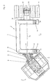
- 1 is the so-called front car and 2 is the The rear of the heavy vehicle according to the invention.
- Front and Rear car are connected to each other via an articulated joint 15, which the Swiveling the front end 1 relative to the rear end 2 by a vertical one Axle allowed for steering the motor vehicle.
- the steering takes place over Hydraulic cylinders 16 and 17.
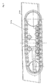
- FIG. 3 is a relative position between the front body 1 and the Rear car 2 shown as they extend by extending the piston / cylinder unit 16th and retracting the piston / cylinder unit 17 compared to those in FIGS. 1 and 2 shown locations can be achieved.
- the front end 1 has a frame 3, a drive motor 4 for driving the heavy vehicle, and Has hydraulic pumps 5, the task of which will be explained below.
- the cab 6 is also supported on the base frame 3, which also drivable front axle 8 of the heavy vehicle carries.
- the drive of the front axle 8 is carried out by a hydraulic motor 7.
- the rear carriage 2 has a for receiving Trough 22 has a fork frame 9 which carries the rear axle 11, which is about a bearing 10 is pivotable, which is mounted on a console 36, which in turn on one of the two Cheeks 35 of the fork frame 9 is attached.
- a piston / cylinder unit 12 is provided, which between the rear cheek 35 of the fork frame 9 and a crank 37 is arranged, which with respect to the rear axle 11 eccentrically arranged bearings 10 of the rear axle the rear axle 11 connects.
- the opening 31 of the fork frame 9 is, as can be seen in FIGS. 2 and 3, arranged to the side of the vehicle.
- a transverse chassis housed as the preferred variant shown in the drawing Crawler track 13, 14 is formed.
- the crawler tracks 13 and 14 are preferably braked independently of one another.
- the frame 3 carries a vertical slewing ring 18, on which the vertical-axis articulated joint 15 is attached.
- the slewing ring 18 allows the Front end 1 opposite rear end 2 about vehicle longitudinal axis 33, thereby preventing road bumps the fork frame 9 by a Load moment.
- the front axle 8 of the heavy vehicle is by means of hydraulic cylinders 20, 21 in trained as prismatic guides 19 upright removable. This makes it possible if the fork frame 9 on the crossways (Crawler tracks 13, 14) is supported against the ground, the front end 1 in relation to the rear carriage 2, until the front axle 8 (or the drive wheels) are no longer in contact with the ground. As soon as the fork frame 9 is supported on the ground via the transverse chassis, the rear axle 11 can also by means of of the piston / cylinder unit 12 pivoted about the rear axle bearing 10 and from Be lifted off the ground until the rear wheels come off the ground.
- Fig. 4 shows a position in which both the front drive wheels and the rear wheels, which may also be driven, from the ground are lifted off. In this position you can use the cross carriages (crawler tracks 13, 14) of the fork frame laterally below with their contact surfaces 32 on the floor resting trough can be moved sideways, causing the trough 22 from the vehicle is discharged.
- the contact surface 32 of the trough 22 projects in the transport position, as shown in FIG. 1 shows the fork frame 9 downwards.
- the footprint can have two feet are formed, which extend across the entire width of the trough Extend vehicle longitudinal axis 32.
- the distance of the Footprint 32 of the trough 22 of the crawler tracks 13, 14 and the lower edge of the fork frame 9 be about 20 cm. This ensures that the trough is released from the fork frame 9 or its front and rear cheeks 34, 35 as soon as the hollow sits on the ground.
- the trough 22 is in the region of its rear end in the direction of travel over a Detachable coupling (docking device) pivotable with the fork frame 9 connected.
- the docking device is released from the trough when the fork frame is lowered against the ground.
- the releasable coupling has a swivel arm 25, which is mounted in a fixed pivot bearing 26 with respect to the frame 9 and the attacks the trough 22.
- the pivot bearing 26 on the console 36 which is fixed to the rear cheek 35 of the fork frame 9 connected, fixed.
- Grips at the front end of the trough 22 in the direction of travel preferably on a horn 28 arranged there, a piston / cylinder assembly 28 with Step cylinder 27 on.
- the step cylinder 27 is in one with respect to the Front axle 8 supporting frame 3 fixed bearing 38 pivotally arranged.
- This bearing 38 is in the illustrated embodiment on the articulation 15 of the the front axle 8 supporting frame 3 attached.
- the piston 38 of the step cylinder 27 can be locked with the trough 22, in particular with its horn 28.
- the latch can be done similarly as is the case with a carabiner. This Locking is required to prevent the trough from swinging up crashes backwards.
- the joint 29 of the stepped cylinder 27 is during settling unlocked by the horn 28 of the trough 22, whereby the stepped cylinder 27 by means of a Piston / cylinder unit 30 acting on the outside of the stepped cylinder 27 from the Area of the horn 28 of the trough 22 can be pivoted out.
- the vehicle shown in the drawing works as follows:
- the front carriage 1 and the rear carriage 2, which can be pivoted via the articulated joint 15 are connected to each other, form the chassis of the truck.
- the fork frame 9 is along the prism guides 19 and by means of the rear axle bearing 10 pivotable rear axle 11 integrated into the cheeks of the fork frame Crawler undercarriages (wheel undercarriages) 13 and 14 can be lowered.
- the Auxiliary cylinder 30 therefore also has the task of the before the settling process Swing the tilt cylinder 27 out of the area of the horn 28.
- Fig. 4 shows the tilting of the trough 22.
- the trough 22 is located on the vehicle in the transport position and the process of tipping takes place in in a known manner by extending the piston 39, which is engaged in the joint 29 Tilting cylinder 27.
- the swivel arm 25 is mechanically so with the trough 22 locks that as soon as the trough is raised even slightly, one erroneous unlocking of the swivel arm 25 is not possible (not in Fig. 4 shown).
- the stepped cylinder 27 with the in the tilted position with the horn 28 Trough 22 locked joint 29 forms with the trough 22 and the pivot bearing 26 a stable triangle that prevents the trough from being thrown backwards.
Landscapes
- Engineering & Computer Science (AREA)
- Transportation (AREA)
- Mechanical Engineering (AREA)
- Body Structure For Vehicles (AREA)
- Handcart (AREA)
Abstract
Description
Claims (7)
- Schwerfahrzeug zum Transport von Mulden mit einer Hubeinrichtung zum Anheben und Absetzen der an einem Gabelrahmen abgestützten Mulde, der die Mulde an drei ihrer Seiten umschließt und an dem die Hinterachse des Fahrzeuges gelagert ist, dadurch gekennzeichnet, daß die Öffnung (31) des Gabelrahmens (9) seitlich des Fahrzeuges angeordnet ist, daß ein bevorzugt am Gabelrahmen (9), insbesondere an dessen sich quer zur Fahrzeuglängsachse (33) erstreckenden Wangen (34, 35) gelagertes Querfahrwerk vorgesehen ist und daß sowohl die Vorderachse (8) des Schwerfahrzeuges als auch dessen Hinterachse (11) über die Hubeinrichtung mit dem Gabelrahmen (9) gekoppelt und sowohl die Vorderachse (8) als auch die Hinterachse (11) gegenüber dem Gabelrahmen (9) anhebbar sind und daß die Aufstandsfläche (32) der Mulde (22), in der Transportstellung, den Gabelrahmen (9) nach unten (gegen die gemeinsame Tangentialebene der Fahrzeugräder) überragt.
- Schwerfahrzeug nach Anspruch 1, dadurch gekennzeichnet, daß das Querfahrwerk von in den sich quer zur Fahrzeuglängsachse erstreckenden Wangen (34, 35) des Gabelrahmens (9) angeordneten Raupenfahrwerken (13, 14) gebildet ist, wobei die Raupenfahrwerke (13, 14) der beiden Wangen (34, 35) bevorzugt mit unterschiedlicher Geschwindigkeit, gegebenenfalls auch unterschiedlicher Richtung steuerbar antreibbar sind.
- Schwerfahrzeug nach Anspruch 1 oder 2, dadurch gekennzeichnet, daß die Hinterachse (11) um ein Lager (10) schwenkbar angeordnet ist, das bezüglich der Hinterachse (11) exzentrisch angeordnet und mit der hinteren Wange (35) des Gabelrahmens (9) bevorzugt über eine Konsole (36) fest verbunden ist, und daß die Vorderachse (8) längs einer, bevorzugt als Prismenführung (19) ausgebildeten, vertikalen Geradführung bewegbar gelagert ist, wobei die Hubeinrichtung zum Anheben und Absetzen der Mulde (22) von, insbesondere hydraulisch betätigbaren, Kolben/Zylinderaggregaten (20, 21; 12) gebildet ist, die voneinander getrennt, der Vorderachse (8) und der Hinterachse (11) zugeordnet sind.
- Schwerfahrzeug nach Anspruch 3, dadurch gekennzeichnet, daß das der Hinterachse (11) zugeordnete Kolben-/Zylinderaggregat (12) zwischen der hinteren Wange (35) des Gabelrahmens (9) und einer Kurbel (37) angeordnet ist, die das bezüglich der Hinterachse (11) exzentrisch angeordnete Lager (10) der Hinterachse mit der Hinterachse (11) verbindet.
- Schwerfahrzeug nach einem der Ansprüche 1 bis 4, dadurch gekennzeichnet, daß die Vorderachse (8) an einem bevorzugt auch das Fahrerhaus (6), gegebenenfalls die Antriebsaggregate (5, 4) für den Fahrantrieb des Fahrzeuges und die Hubeinrichtung tragenden, Rahmen (3) gelagert ist, der einen um eine horizontale Achse schwenkbaren Drehkranz (18) für ein vertikalachsiges Knickgelenk (15) trägt, an dem der Gabelrahmen (9), bevorzugt die vordere Wange (34) des Gabelrahmens (9), befestigt ist.
- Schwerfahrzeug, mit einer anheb- und absenkbaren Mulde und einem Rahmen, an dem die Mulde abgestützt ist, insbesondere nach einem der Ansprüche 1 bis 5, dadurch gekennzeichnet, daß die Mulde (22) im Bereich ihres in Fahrtrichtung hinteren Endes über eine lösbare Kupplung (Andockvorrichtung) schwenkbar mit dem Rahmen (9) verbunden ist und daß beispielsweise die lösbare Kupplung einen Schwenkarm (25) aufweist, der in einem bezüglich des Rahmens (9) ortsfesten Schwenklager (26) gelagert ist und an der Mulde (22) angreift und daß an dem in Fahrtrichtung vorderen Ende der Mulde (22), bevorzugt an einem dort angeordneten Horn (28) ein Kolben-/Zylinderaggregat mit Stufenzylinder (27) angreift, der schwenkbar an einem bezüglich des die Vorderachse (8) tragenden Rahmens (3) ortsfesten Lagers (38), das bevorzugt am Knickgelenk (15) des die Vorderachse (8) tragenden Rahmens (3) angeordnet ist, gelagert ist und dessen Kolben (39) mit der Mulde (22), insbesondere mit deren Horn (28), bevorzugt verrastbar ausgebildet ist.
- Schwerfahrzeug nach Anspruch 6, dadurch gekennzeichnet, daß an dem mit Stufenzylinder (27) ausgebildeten Kolben-/Zylinderaggregat ein weiteres Kolben-/Zylinderaggregat (30) außen am Zylindermantel angreift.
Applications Claiming Priority (2)
| Application Number | Priority Date | Filing Date | Title |
|---|---|---|---|
| AT56199 | 1999-03-25 | ||
| AT56199A AT407135B (de) | 1999-03-25 | 1999-03-25 | Schwerfahrzeug |
Publications (2)
| Publication Number | Publication Date |
|---|---|
| EP1038724A2 true EP1038724A2 (de) | 2000-09-27 |
| EP1038724A3 EP1038724A3 (de) | 2003-06-18 |
Family
ID=3493874
Family Applications (1)
| Application Number | Title | Priority Date | Filing Date |
|---|---|---|---|
| EP00890097A Withdrawn EP1038724A3 (de) | 1999-03-25 | 2000-03-24 | Schwerfahrzeug |
Country Status (2)
| Country | Link |
|---|---|
| EP (1) | EP1038724A3 (de) |
| AT (1) | AT407135B (de) |
Families Citing this family (2)
| Publication number | Priority date | Publication date | Assignee | Title |
|---|---|---|---|---|
| CN112124182B (zh) * | 2020-08-26 | 2024-04-09 | 陕西未来筑业实业有限公司 | 罐体用卸料振动辅助装置及举升式全封闭物料运输车 |
| DE102022101937A1 (de) | 2022-01-27 | 2023-07-27 | Wacker Neuson Linz Gmbh | Baufahrzeug |
Family Cites Families (6)
| Publication number | Priority date | Publication date | Assignee | Title |
|---|---|---|---|---|
| SE390806B (sv) * | 1974-03-15 | 1977-01-24 | K W Berglund | Transportfordon |
| US4213726A (en) * | 1978-07-24 | 1980-07-22 | Raygo Wagner, Inc. | Container carrier vehicle |
| SE429629B (sv) * | 1981-08-24 | 1983-09-19 | Kiruna Truck Ab | U-ramstruck |
| DE3225186C2 (de) * | 1982-07-06 | 1987-01-22 | Ruhrkohle Ag, 4300 Essen | Transportfahrzeug für den gleislosen Material- und Personentransport |
| US4968097A (en) * | 1989-08-03 | 1990-11-06 | Kress Corporation | Elevatable dump box carrier with tilt frame and abuttable rear latch |
| FR2741024B1 (fr) * | 1995-11-13 | 1998-02-06 | Regie Autonome Transports | Plate-forme mobile pour le franchissement de denivellations en degre |
-
1999
- 1999-03-25 AT AT56199A patent/AT407135B/de not_active IP Right Cessation
-
2000
- 2000-03-24 EP EP00890097A patent/EP1038724A3/de not_active Withdrawn
Non-Patent Citations (1)
| Title |
|---|
| None |
Also Published As
| Publication number | Publication date |
|---|---|
| AT407135B (de) | 2000-12-27 |
| EP1038724A3 (de) | 2003-06-18 |
| ATA56199A (de) | 2000-05-15 |
Similar Documents
| Publication | Publication Date | Title |
|---|---|---|
| EP0909854B1 (de) | Laderfahrzeug | |
| DE69431516T2 (de) | Fahrzeug mit einem u-förmigen rahmen | |
| EP0093873B1 (de) | Kraftfahrzeug zum Transportieren und Verlegen einer Festbrücke | |
| DE202016008705U1 (de) | Hebbare Tragvorrichtung | |
| EP0012236A1 (de) | Fahrzeug mit verstellbarem Belastungsgewicht | |
| DE1924968A1 (de) | Zusatzgeraet,insbesondere fuer Gabelstapler einschliesslich Seitenlader | |
| DE3534626C2 (de) | ||
| DE2608342C2 (de) | ||
| DE2015792C2 (de) | Als Ackerschlepper einzusetzendes landwirtschaftliches Fahrzeug | |
| DE3708066A1 (de) | Nutzfahrzeug mit wechselaufbau | |
| DE3819644A1 (de) | Von einem fahrzeug gehaltenes arbeitsgeraet fuer erdarbeiten, insbesondere schaufellader | |
| AT407135B (de) | Schwerfahrzeug | |
| EP0198042A1 (de) | Einachsanhänger. | |
| DE69708361T2 (de) | Selbstladender Wagen mit Ladearm | |
| DD146637A5 (de) | Abtrags-becherwerkslader | |
| EP0940291B1 (de) | Strassenfahrzeug zum Transport und Magazinieren von Verkehrsschildern | |
| DE2811797A1 (de) | Vorrichtung zum verladen von guetern | |
| DE69319398T2 (de) | Handhabungsfahrzeug | |
| EP0630779A2 (de) | Nutzfahrzeug zum Aufnehmen und Absetzen von Containern sowie zugehöriges Umsetzsystem | |
| DE19840151B4 (de) | Abstützstruktur für Radfahrzeuge | |
| DE2327516C3 (de) | Fahrzeug zum Transport ausschließlich von Stahlbetonraumzellen, insbesondere von Stahlbetonfertiggaragen | |
| EP0286576B1 (de) | Transportfahrzeug | |
| DE2906623A1 (de) | Mobiler foerderstromvergleichmaessiger | |
| DE3431561A1 (de) | Nutzfahrzeug mit kombinierter verladeeinrichtung | |
| DE3345512C2 (de) | Fahrzeug für den Transport von Raumzellen, insbesondere Stahlbetonfertiggaragen auf einem Hilfsrahmen eines Aufliegers |
Legal Events
| Date | Code | Title | Description |
|---|---|---|---|
| PUAI | Public reference made under article 153(3) epc to a published international application that has entered the european phase |
Free format text: ORIGINAL CODE: 0009012 |
|
| AK | Designated contracting states |
Kind code of ref document: A2 Designated state(s): AT BE CH CY DE DK ES FI FR GB GR IE IT LI LU MC NL PT SE |
|
| AX | Request for extension of the european patent |
Free format text: AL;LT;LV;MK;RO;SI |
|
| PUAL | Search report despatched |
Free format text: ORIGINAL CODE: 0009013 |
|
| AK | Designated contracting states |
Designated state(s): AT BE CH CY DE DK ES FI FR GB GR IE IT LI LU MC NL PT SE |
|
| AX | Request for extension of the european patent |
Extension state: AL LT LV MK RO SI |
|
| RIC1 | Information provided on ipc code assigned before grant |
Ipc: 7B 60P 1/34 B Ipc: 7B 60P 1/64 B Ipc: 7B 60P 1/16 A |
|
| AKX | Designation fees paid | ||
| REG | Reference to a national code |
Ref country code: DE Ref legal event code: 8566 |
|
| STAA | Information on the status of an ep patent application or granted ep patent |
Free format text: STATUS: THE APPLICATION IS DEEMED TO BE WITHDRAWN |
|
| 18D | Application deemed to be withdrawn |
Effective date: 20031219 |