EP1040037B1 - Dispositif pour assister le mouvement de deplacement et pour le verrouillage elastique de parties d'aiguillage mobiles - Google Patents
Dispositif pour assister le mouvement de deplacement et pour le verrouillage elastique de parties d'aiguillage mobiles Download PDFInfo
- Publication number
- EP1040037B1 EP1040037B1 EP98962124A EP98962124A EP1040037B1 EP 1040037 B1 EP1040037 B1 EP 1040037B1 EP 98962124 A EP98962124 A EP 98962124A EP 98962124 A EP98962124 A EP 98962124A EP 1040037 B1 EP1040037 B1 EP 1040037B1
- Authority
- EP
- European Patent Office
- Prior art keywords
- rod
- tube
- locking members
- recesses
- compression spring
- Prior art date
- Legal status (The legal status is an assumption and is not a legal conclusion. Google has not performed a legal analysis and makes no representation as to the accuracy of the status listed.)
- Expired - Lifetime
Links
Images


Classifications
-
- B—PERFORMING OPERATIONS; TRANSPORTING
- B61—RAILWAYS
- B61L—GUIDING RAILWAY TRAFFIC; ENSURING THE SAFETY OF RAILWAY TRAFFIC
- B61L5/00—Local operating mechanisms for points or track-mounted scotch-blocks; Visible or audible signals; Local operating mechanisms for visible or audible signals
- B61L5/10—Locking mechanisms for points; Means for indicating the setting of points
Definitions
- the invention relates to a device for support the sliding movement and for the elastic locking of movable Turnout parts, especially turnout tongues of Rili rail turnouts, with an axially movable pipe or Rod, which has recesses for the Includes receiving radially displaceable locking members and one concentrically surrounding the pipe or rod Pipe, which has recesses for receiving radially outwards has displaced locking members.
- a changeover aid are also from AT-PS 379 624 already known, with a spring rocker used came at an angle lever at the crossing point of the arms is mounted, an energy accumulator by means of a compression spring is supported against the arms of the two angle levers.
- Two spring rockers were here over a coupling rod with the two tongue rails connected.
- the invention now aims to set up a device mentioned type to the extent that they are particularly compact and can be trained short and both at Rail switch adjustment drives as well as a conversion aid for Turnouts can be used.
- the compact training should the subsequent retrofitting of existing switches in a simple way Allow wise and especially for grooved rail switches be suitable.
- the training according to the invention consists essentially in that the locking members in two separate at an axial distance from each other between the tube and pipe sections or cages arranged on the rod are stored, and that between the pipe sections or cages one in axial Direction acting compression spring is arranged. Because now two separate pipe sections or Ball cages are arranged, the arrangement of a single is sufficient Compression spring between these pipe sections in order at appropriate Arrangement of the recesses for the locking members resilient support of the changeover movement as well as a resilient Ensure that the end position is locked. Overall, the entire arrangement in a single fixed outer tube locked on the outside and thus against ingress of dirt be trained so that operational safety without maintenance guaranteed over a long service life.
- the training is such that the axial distance of the recesses for the locking members in Pipe different from the axial distance of the recesses on the Rod is selected.
- the outer tube is advantageously arranged stationary, the rod as the switch tongues in a particularly simple manner connecting coupling rod can be formed.
- a such coupling rod connecting the switch tongues can directly be connected to a drive, so that instead of existing operating rod of the point machine simply the Device according to the invention used directly as a drive rod can be. With regard to the compact dimensions existing coupling rods can be replaced without any structural Changes.
- the inventive design is particularly advantageous made so that the recesses for the locking members as circumferential or ring grooves and the locking members are designed as balls.
- the bearing construction known to be designed as ball cages, so that a particularly simple training is made possible.
- the training is advantageously made so that the annular grooves have a trapezoidal cross section.
- the closed design according to the invention and the compact Training can also be an additional hydraulic Damping and thus a reduction in noise during the changeover process realize in a simple way. It is an advantage here the training taken so that the cages for the locking members are sealingly guided between the rod and tube, and that the annular space containing the compression spring opens outwards Check valves and one parallel to each of these valves switched throttle with those located outside the spring chamber Annular spaces is connected. With such training the final phase of the changeover movement is hydraulically damped, whereby the fluid from the outer annular space into the spring space is pressed back. With appropriate dimensioning of the cross sections can do this with complete filling of the annular spaces Fluid can be ensured.
- the shifting movement can be used be ensured that the spring in the first part of the displacement movement can be further compressed to subsequently under partial relaxation the stored spring force as a changeover aid again to provide. It is therefore advantageous the training so that the compression spring in one End position of the device corresponding position partially relaxed is.
- the compression spring can be used as Coil spring be formed.
- FIG. 1 shows a view of the adjustment device according to the invention partly in section with the point machine
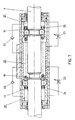
- Fig. 2 a plan view of the changeover in the direction of arrow II
- 3 shows an enlarged view of the invention Device in a first left end position
- Fig.4 a Representation analogous to Figure 3 in a transition position during the Switching movement
- Fig.5 the beginning of the relaxation of the compression spring to support the changeover movement to the right
- Fig. 6 the right end position of the device according to the invention and FIG schematic representation of an additional hydraulic damping in a training according to Figures 3 to 6.
- a grooved rail switch can be seen, the movable switch tongues with 1 and the stock rails with 2 are.
- the switch tongues 1 are with coupling pins 3 a rod 4 coupled, which itself by a schematic indicated drive 5 in the direction of the double arrow 6 is.
- the device according to the invention is shown schematically at 7 to support the sliding movement and for elastic Lock the tongue rails 1 shown, which in the the following Fig. 3 to 7 is clarified.
- the rod 4 has on her Scope in cross-section trapezoidal grooves 10 and 11, the axial distance with b is selected.
- ball cages 12 and 13 are the locking members 14 and 15 formed as balls arranged.
- the fixed outer tube 16 has grooves 17, the effective axial distance of these grooves 17 from each other is selected differently from the distance b.
- the rod 4 succeeds in the right end position in which the resilient system the right tongue under the action of the compression spring 18 guaranteed is.
- the locking members 14 are here in their outer position in the recesses 17 of the fixed tube 16th added, whereas the locking members 15 in their radially inwardly shifted position in the groove 11 of the rod are so that the rod over the locking members 15th by the force of the spring 18 in the direction of arrow 19 right is pressed.
Landscapes
- Mechanical Engineering (AREA)
- Engineering & Computer Science (AREA)
- Fluid-Damping Devices (AREA)
- Push-Button Switches (AREA)
- Rear-View Mirror Devices That Are Mounted On The Exterior Of The Vehicle (AREA)
- Train Traffic Observation, Control, And Security (AREA)
- Lock And Its Accessories (AREA)
- Spinning Or Twisting Of Yarns (AREA)
- Moving Of Heads (AREA)
- Mechanical Control Devices (AREA)
- Arc-Extinguishing Devices That Are Switches (AREA)
- Gear-Shifting Mechanisms (AREA)
- Springs (AREA)
- Railway Tracks (AREA)
- Bearings For Parts Moving Linearly (AREA)
- Transmission Devices (AREA)
- Gears, Cams (AREA)
- Automatic Assembly (AREA)
Claims (10)
- Dispositif pour assister le mouvement de coulissement et pour verrouiller élastiquement des parties d'aiguillage mobiles, en particulier des lames d'aiguillage, de rails à gorge, comportant un tube qui peut coulisser axialement ou une barre (4) qui peut coulisser axialement et qui présente à sa périphérie des évidements (10, 11) pour recevoir des éléments de verrouillage pouvant coulisser radialement, ainsi qu'un tube (16) qui entoure concentriquement le tube ou la barre et présente des évidements (17) pour recevoir les éléments de verrouillage (14, 15) qui ont coulissé radialement vers l'extérieur et qu'un ressort de compression agissant selon la direction axiale, caractérisé par le fait que les éléments de verrouillage (14, 15) sont portés dans deux tronçons tubulaires ou cages (12, 13) distincts, disposés à une certaine distance axiale l'un de l'autre entre le tube (16) et le tube ou la barre (4) pouvant coulisser axialement, et que le ressort de compression (18) est disposé entre les tronçons tubulaires ou les cages (12, 13).
- Dispositif selon la revendication 1, caractérisé par le fait que la distance axiale des évidements (17) prévus dans le tube (16) pour les éléments de verrouillage (14, 15) est choisie différente de la distance axiale des évidements (10, 11) prévus dans la barre (4).
- Dispositif selon la revendication 1 ou 2, caractérisé par le fait que le tube (16) situé à l'extérieur est disposé fixe en position.
- Dispositif selon la revendication 1, 2 ou 3, caractérisé par le fait que la barre (4) est conçue sous forme de barre d'accouplement reliant les lames d'aiguillage (1).
- Dispositif selon l'une des revendications 1 à 4, caractérisé par le fait que les évidements (10, 11, 17) pour les éléments de verrouillage (14, 15) sont conçus sous forme de rainures périphériques ou annulaires et les éléments de verrouillage (14, 15), sous forme de sphères.
- Dispositif selon l'une des revendications 1 à 5, caractérisé par le fait que les rainures annulaires (10, 11, 17) présentent une section trapézoïdale.
- Dispositif selon l'une des revendications 1 à 6, caractérisé par le fait que les cages (12, 13) pour les éléments de verrouillage (14, 15) sont guidées, avec étanchéité, entre barre (4) et tube (16) et que l'espace annulaire contenant le ressort de compression (18) est relié avec les espaces annulaires (21) situés à l'extérieur de l'espace au ressort (20) par l'intermédiaire de clapets de non-retour (22) ouvrant vers l'extérieur et de, pour chacun, un étranglement (23) monté en parallèle à ces clapets (22).
- Dispositif selon l'une des revendications 1 à 7, caractérisé par le fait que le ressort de compression (18) est partiellement détendu dans sa position correspondant à une position d'extrémité du dispositif.
- Dispositif selon l'une des revendications 1 à 8, caractérisé par le fait que le ressort de compression (18) est conçu sous forme de ressort hélicoïdal.
- Dispositif selon l'une des revendications 1 à 9, caractérisé par le fait que la barre (4) porte des butées (8) qui, dans chacune des positions d'extrémité du dispositif, collaborent avec des dispositifs d'amortissement, en particulier avec un amortisseur hydraulique (9).
Applications Claiming Priority (3)
| Application Number | Priority Date | Filing Date | Title |
|---|---|---|---|
| AT0213797A AT406038B (de) | 1997-12-17 | 1997-12-17 | Einrichtung zum unterstützen der verschiebebewegung und zum elastischen verriegeln von beweglichen weichenteilen |
| AT213797 | 1997-12-17 | ||
| PCT/AT1998/000308 WO1999030951A1 (fr) | 1997-12-17 | 1998-12-16 | Dispositif pour assister le mouvement de deplacement et pour le verrouillage elastique de parties d'aiguillage mobiles |
Publications (2)
| Publication Number | Publication Date |
|---|---|
| EP1040037A1 EP1040037A1 (fr) | 2000-10-04 |
| EP1040037B1 true EP1040037B1 (fr) | 2002-09-11 |
Family
ID=3528567
Family Applications (1)
| Application Number | Title | Priority Date | Filing Date |
|---|---|---|---|
| EP98962124A Expired - Lifetime EP1040037B1 (fr) | 1997-12-17 | 1998-12-16 | Dispositif pour assister le mouvement de deplacement et pour le verrouillage elastique de parties d'aiguillage mobiles |
Country Status (13)
| Country | Link |
|---|---|
| EP (1) | EP1040037B1 (fr) |
| AT (2) | AT406038B (fr) |
| AU (1) | AU1743399A (fr) |
| BG (1) | BG63867B1 (fr) |
| DE (1) | DE59805554D1 (fr) |
| EE (1) | EE04361B1 (fr) |
| HR (1) | HRP20000330B1 (fr) |
| HU (1) | HU222204B1 (fr) |
| NO (1) | NO20002981D0 (fr) |
| PL (1) | PL192789B1 (fr) |
| PT (1) | PT1040037E (fr) |
| SK (2) | SK2545U (fr) |
| WO (1) | WO1999030951A1 (fr) |
Families Citing this family (8)
| Publication number | Priority date | Publication date | Assignee | Title |
|---|---|---|---|---|
| AT407984B (de) | 1999-05-14 | 2001-07-25 | Vae Ag | Einrichtung zum verstellen und zum elastischen verriegeln von beweglichen weichenteilen |
| NL1016157C2 (nl) * | 2000-09-12 | 2002-03-13 | Nma Railway Signalling B V | Krachtbegrenzer. |
| AT411047B (de) * | 2001-01-11 | 2003-09-25 | Vae Eisenbahnsysteme Gmbh | Einrichtung zum verriegeln der endlagen von beweglichen weichenteilen |
| AT500296B1 (de) * | 2003-10-31 | 2006-12-15 | Vae Gmbh | Einrichtung zum verriegeln von endlagen von beweglichen weichenteilen, insbesondere weichenverschluss |
| BG64769B1 (bg) * | 2003-11-12 | 2006-03-31 | "Дендрит" Оод | Съединение за заключване езиците на железопътни стрелки |
| GB2483691B (en) * | 2010-09-16 | 2015-07-01 | Spx Internat Ltd | Mechanical lock for Railway points |
| US8684318B2 (en) | 2010-09-16 | 2014-04-01 | Spx International Limited | Mechanical lock |
| FR3059621B1 (fr) * | 2016-12-01 | 2019-07-12 | Vossloh Cogifer | Mecanisme de deplacement et blocage en position d'au moins une aiguille de rail |
Family Cites Families (9)
| Publication number | Priority date | Publication date | Assignee | Title |
|---|---|---|---|---|
| FR1175137A (fr) * | 1957-05-15 | 1959-03-20 | Appareil d'entraînement et de verrouillage | |
| DE2049873A1 (de) * | 1970-10-10 | 1972-04-13 | Goldschmidt Ag Th | Selbstverriegelnde Stellvorrichtung |
| DE2850855C3 (de) * | 1978-11-24 | 1981-08-13 | Fabeg Gmbh, 7518 Bretten | Axiale Überlastkupplung bei Weichenantrieben |
| DK0467865T3 (da) * | 1990-07-19 | 1994-10-31 | Siliani Angiolo Spa | Apparat til betjening af skiftetunger i jernbanesporskifter |
| SI9300651A (en) * | 1992-12-17 | 1994-06-30 | Voest Alpine Eisenbahnsysteme | Device for bolding movable parts of railway switches |
| JP2678869B2 (ja) * | 1993-06-24 | 1997-11-19 | 日本鉄道建設公団 | 転てつ機 |
| AT403462B (de) * | 1995-05-03 | 1998-02-25 | Vae Ag | Einrichtung zum umstellen von weichen |
| AT403463B (de) * | 1995-12-14 | 1998-02-25 | Vae Ag | Einrichtung zum sichern der endlagen von weichen- und kreuzungsstellantrieben |
| AT405925B (de) * | 1997-05-27 | 1999-12-27 | Vae Ag | Einrichtung zum verriegeln der endlagen von beweglichen weichenteilen |
-
1997
- 1997-12-17 AT AT0213797A patent/AT406038B/de not_active IP Right Cessation
-
1998
- 1998-12-16 EP EP98962124A patent/EP1040037B1/fr not_active Expired - Lifetime
- 1998-12-16 HU HU0004524A patent/HU222204B1/hu not_active IP Right Cessation
- 1998-12-16 EE EEP200000332A patent/EE04361B1/xx not_active IP Right Cessation
- 1998-12-16 WO PCT/AT1998/000308 patent/WO1999030951A1/fr not_active Ceased
- 1998-12-16 PL PL341150A patent/PL192789B1/pl not_active IP Right Cessation
- 1998-12-16 AU AU17433/99A patent/AU1743399A/en not_active Abandoned
- 1998-12-16 HR HR980262A patent/HRP20000330B1/xx not_active IP Right Cessation
- 1998-12-16 AT AT98962124T patent/ATE223825T1/de active
- 1998-12-16 PT PT98962124T patent/PT1040037E/pt unknown
- 1998-12-16 SK SK18-2000U patent/SK2545U/sk unknown
- 1998-12-16 DE DE59805554T patent/DE59805554D1/de not_active Expired - Lifetime
- 1998-12-16 SK SK88-2000A patent/SK882000A3/sk unknown
-
2000
- 2000-06-09 NO NO20002981A patent/NO20002981D0/no not_active Application Discontinuation
- 2000-07-14 BG BG104610A patent/BG63867B1/bg unknown
Also Published As
| Publication number | Publication date |
|---|---|
| PT1040037E (pt) | 2003-01-31 |
| HRP20000330B1 (en) | 2001-10-31 |
| ATA213797A (de) | 1999-06-15 |
| PL192789B1 (pl) | 2006-12-29 |
| HU222204B1 (hu) | 2003-05-28 |
| SK2545U (sk) | 2000-07-11 |
| EE200000332A (et) | 2001-08-15 |
| PL341150A1 (en) | 2001-03-26 |
| SK882000A3 (en) | 2000-08-14 |
| EP1040037A1 (fr) | 2000-10-04 |
| WO1999030951A1 (fr) | 1999-06-24 |
| HRP20000330A2 (en) | 2000-12-31 |
| NO20002981L (no) | 2000-06-09 |
| AU1743399A (en) | 1999-07-05 |
| DE59805554D1 (de) | 2002-10-17 |
| HUP0004524A3 (en) | 2002-01-28 |
| ATE223825T1 (de) | 2002-09-15 |
| EE04361B1 (et) | 2004-10-15 |
| NO20002981D0 (no) | 2000-06-09 |
| BG63867B1 (bg) | 2003-04-30 |
| BG104610A (en) | 2001-02-28 |
| HUP0004524A2 (hu) | 2001-04-28 |
| AT406038B (de) | 2000-01-25 |
Similar Documents
| Publication | Publication Date | Title |
|---|---|---|
| DE102011053852B4 (de) | Werkzeug zum Zerkleinern von Koks | |
| DE2849267C2 (de) | Gasfeder | |
| EP2929208B1 (fr) | Frein à disque et ressort de retenue d'un tel frein à disque | |
| DE2255376A1 (de) | Stellvorrichtung fuer ventile | |
| EP0984881B1 (fr) | Dispositif pour verrouiller des positions finales extremes de pieces d'aiguillage mobiles | |
| DE60004168T2 (de) | Hydraulische maschine oder motor mit hin- und herbeweglichem differenzialkolben | |
| EP0764804B1 (fr) | Assemblage écrou-broche filetée | |
| EP1040037B1 (fr) | Dispositif pour assister le mouvement de deplacement et pour le verrouillage elastique de parties d'aiguillage mobiles | |
| EP0982018A2 (fr) | Dispositif de levage de préfèrence pour le réglage en hauteur de lits de malades ou de soins | |
| EP1349764B1 (fr) | Dispositif permettant de verrouiller les positions terminales d'aiguilles mobiles | |
| EP0684174A1 (fr) | Dispositif de verrouillage pour pièces d'aiguillage de chemin de fer | |
| DE3136311A1 (de) | "druckmittelbetaetigter arbeitszylinder" | |
| EP1883567A1 (fr) | Dispositif pour verifier la position extreme de pieces mobiles d'un aiguillage de voie ferree | |
| DE112008002949B4 (de) | Zugschlitten für Gewinnungshobel | |
| DE4313564C1 (de) | Schaltvorrichtung für ein Zahnräderwechselgetriebe eines Kraftfahrzeuges | |
| DE102009007351A1 (de) | Andruckleitung für eine Kraftfahrzeugzahnstangenlenkung | |
| EP1180080B1 (fr) | Dispositif pour regler et verrouiller de maniere elastique des elements d'aiguillage mobiles | |
| EP1138052B1 (fr) | Accumulateur d'energie pour commutateur a plots | |
| DE2619469C2 (de) | Hülsenpuffer zur federnden Aufnahme von Stoßkräften, insbesondere für Schienenfahrzeuge | |
| EP0511581B1 (fr) | Frein à étrier flottant et axe pour un tel frein | |
| EP0779197B1 (fr) | Dispositif de sécurité de positions de fin de course de commandes de positionnement pour aiguillages et croisements | |
| EP1678024B1 (fr) | Dispositif de verrouillage d'elements mobiles d'aiguillage, notamment fermeture d'aiguillage | |
| CH617893A5 (en) | Device for absorbing impact forces in a resilient fashion | |
| DE2519973C3 (de) | Entlastungsventil | |
| DE2122846A1 (de) | Steuerstabantrieb für Kernreaktoren |
Legal Events
| Date | Code | Title | Description |
|---|---|---|---|
| PUAI | Public reference made under article 153(3) epc to a published international application that has entered the european phase |
Free format text: ORIGINAL CODE: 0009012 |
|
| 17P | Request for examination filed |
Effective date: 20000623 |
|
| AK | Designated contracting states |
Kind code of ref document: A1 Designated state(s): AT BE CH DE DK ES FI FR GB GR IE IT LI LU NL PT SE |
|
| AX | Request for extension of the european patent |
Free format text: LT PAYMENT 20000623;LV PAYMENT 20000623;RO PAYMENT 20000623;SI PAYMENT 20000623 |
|
| GRAG | Despatch of communication of intention to grant |
Free format text: ORIGINAL CODE: EPIDOS AGRA |
|
| 17Q | First examination report despatched |
Effective date: 20010913 |
|
| GRAG | Despatch of communication of intention to grant |
Free format text: ORIGINAL CODE: EPIDOS AGRA |
|
| GRAH | Despatch of communication of intention to grant a patent |
Free format text: ORIGINAL CODE: EPIDOS IGRA |
|
| GRAH | Despatch of communication of intention to grant a patent |
Free format text: ORIGINAL CODE: EPIDOS IGRA |
|
| GRAA | (expected) grant |
Free format text: ORIGINAL CODE: 0009210 |
|
| AK | Designated contracting states |
Kind code of ref document: B1 Designated state(s): AT BE CH DE DK ES FI FR GB GR IE IT LI LU NL PT SE |
|
| AX | Request for extension of the european patent |
Free format text: LT PAYMENT 20000623;LV PAYMENT 20000623;RO PAYMENT 20000623;SI PAYMENT 20000623 |
|
| PG25 | Lapsed in a contracting state [announced via postgrant information from national office to epo] |
Ref country code: IE Free format text: LAPSE BECAUSE OF FAILURE TO SUBMIT A TRANSLATION OF THE DESCRIPTION OR TO PAY THE FEE WITHIN THE PRESCRIBED TIME-LIMIT Effective date: 20020911 Ref country code: GR Free format text: LAPSE BECAUSE OF FAILURE TO SUBMIT A TRANSLATION OF THE DESCRIPTION OR TO PAY THE FEE WITHIN THE PRESCRIBED TIME-LIMIT Effective date: 20020911 Ref country code: FI Free format text: LAPSE BECAUSE OF FAILURE TO SUBMIT A TRANSLATION OF THE DESCRIPTION OR TO PAY THE FEE WITHIN THE PRESCRIBED TIME-LIMIT Effective date: 20020911 |
|
| REF | Corresponds to: |
Ref document number: 223825 Country of ref document: AT Date of ref document: 20020915 Kind code of ref document: T |
|
| REG | Reference to a national code |
Ref country code: GB Ref legal event code: FG4D Free format text: NOT ENGLISH |
|
| REG | Reference to a national code |
Ref country code: CH Ref legal event code: EP |
|
| REG | Reference to a national code |
Ref country code: IE Ref legal event code: FG4D Free format text: GERMAN |
|
| REF | Corresponds to: |
Ref document number: 59805554 Country of ref document: DE Date of ref document: 20021017 |
|
| REG | Reference to a national code |
Ref country code: CH Ref legal event code: NV Representative=s name: PPS POLYVALENT PATENT SERVICE AG |
|
| PG25 | Lapsed in a contracting state [announced via postgrant information from national office to epo] |
Ref country code: DK Free format text: LAPSE BECAUSE OF FAILURE TO SUBMIT A TRANSLATION OF THE DESCRIPTION OR TO PAY THE FEE WITHIN THE PRESCRIBED TIME-LIMIT Effective date: 20021211 |
|
| GBT | Gb: translation of ep patent filed (gb section 77(6)(a)/1977) |
Effective date: 20021130 |
|
| PG25 | Lapsed in a contracting state [announced via postgrant information from national office to epo] |
Ref country code: BE Free format text: LAPSE BECAUSE OF NON-PAYMENT OF DUE FEES Effective date: 20021231 |
|
| REG | Reference to a national code |
Ref country code: PT Ref legal event code: SC4A Free format text: AVAILABILITY OF NATIONAL TRANSLATION Effective date: 20021205 |
|
| LTIE | Lt: invalidation of european patent or patent extension |
Effective date: 20020911 |
|
| ET | Fr: translation filed | ||
| PG25 | Lapsed in a contracting state [announced via postgrant information from national office to epo] |
Ref country code: ES Free format text: LAPSE BECAUSE OF FAILURE TO SUBMIT A TRANSLATION OF THE DESCRIPTION OR TO PAY THE FEE WITHIN THE PRESCRIBED TIME-LIMIT Effective date: 20030328 |
|
| REG | Reference to a national code |
Ref country code: IE Ref legal event code: FD4D Ref document number: 1040037E Country of ref document: IE |
|
| BERE | Be: lapsed |
Owner name: *VAE A.G. Effective date: 20021231 |
|
| PLBE | No opposition filed within time limit |
Free format text: ORIGINAL CODE: 0009261 |
|
| STAA | Information on the status of an ep patent application or granted ep patent |
Free format text: STATUS: NO OPPOSITION FILED WITHIN TIME LIMIT |
|
| 26N | No opposition filed |
Effective date: 20030612 |
|
| PGFP | Annual fee paid to national office [announced via postgrant information from national office to epo] |
Ref country code: GB Payment date: 20101221 Year of fee payment: 13 |
|
| PGFP | Annual fee paid to national office [announced via postgrant information from national office to epo] |
Ref country code: SE Payment date: 20111223 Year of fee payment: 14 Ref country code: PT Payment date: 20111216 Year of fee payment: 14 Ref country code: CH Payment date: 20111227 Year of fee payment: 14 Ref country code: NL Payment date: 20111228 Year of fee payment: 14 Ref country code: LU Payment date: 20111223 Year of fee payment: 14 Ref country code: FR Payment date: 20120105 Year of fee payment: 14 |
|
| REG | Reference to a national code |
Ref country code: CH Ref legal event code: PFA Owner name: VAE AKTIENGESELLSCHAFT Free format text: VAE AKTIENGESELLSCHAFT#ROTENTURMSTRASSE 5-9#1010 WIEN (AT) -TRANSFER TO- VAE AKTIENGESELLSCHAFT#ROTENTURMSTRASSE 5-9#1010 WIEN (AT) |
|
| PGFP | Annual fee paid to national office [announced via postgrant information from national office to epo] |
Ref country code: DE Payment date: 20111222 Year of fee payment: 14 |
|
| PGFP | Annual fee paid to national office [announced via postgrant information from national office to epo] |
Ref country code: IT Payment date: 20111229 Year of fee payment: 14 |
|
| REG | Reference to a national code |
Ref country code: PT Ref legal event code: MM4A Free format text: LAPSE DUE TO NON-PAYMENT OF FEES Effective date: 20130617 |
|
| REG | Reference to a national code |
Ref country code: NL Ref legal event code: V1 Effective date: 20130701 |
|
| PG25 | Lapsed in a contracting state [announced via postgrant information from national office to epo] |
Ref country code: SE Free format text: LAPSE BECAUSE OF NON-PAYMENT OF DUE FEES Effective date: 20121217 |
|
| REG | Reference to a national code |
Ref country code: CH Ref legal event code: PL |
|
| GBPC | Gb: european patent ceased through non-payment of renewal fee |
Effective date: 20121216 |
|
| PG25 | Lapsed in a contracting state [announced via postgrant information from national office to epo] |
Ref country code: PT Free format text: LAPSE BECAUSE OF NON-PAYMENT OF DUE FEES Effective date: 20130617 |
|
| REG | Reference to a national code |
Ref country code: FR Ref legal event code: ST Effective date: 20130830 |
|
| PG25 | Lapsed in a contracting state [announced via postgrant information from national office to epo] |
Ref country code: NL Free format text: LAPSE BECAUSE OF NON-PAYMENT OF DUE FEES Effective date: 20130701 Ref country code: CH Free format text: LAPSE BECAUSE OF NON-PAYMENT OF DUE FEES Effective date: 20121231 Ref country code: LI Free format text: LAPSE BECAUSE OF NON-PAYMENT OF DUE FEES Effective date: 20121231 Ref country code: DE Free format text: LAPSE BECAUSE OF NON-PAYMENT OF DUE FEES Effective date: 20130702 |
|
| REG | Reference to a national code |
Ref country code: DE Ref legal event code: R119 Ref document number: 59805554 Country of ref document: DE Effective date: 20130702 |
|
| PG25 | Lapsed in a contracting state [announced via postgrant information from national office to epo] |
Ref country code: FR Free format text: LAPSE BECAUSE OF NON-PAYMENT OF DUE FEES Effective date: 20130102 Ref country code: GB Free format text: LAPSE BECAUSE OF NON-PAYMENT OF DUE FEES Effective date: 20121216 |
|
| PG25 | Lapsed in a contracting state [announced via postgrant information from national office to epo] |
Ref country code: IT Free format text: LAPSE BECAUSE OF NON-PAYMENT OF DUE FEES Effective date: 20121216 |
|
| PG25 | Lapsed in a contracting state [announced via postgrant information from national office to epo] |
Ref country code: LU Free format text: LAPSE BECAUSE OF NON-PAYMENT OF DUE FEES Effective date: 20121216 |
|
| PGFP | Annual fee paid to national office [announced via postgrant information from national office to epo] |
Ref country code: AT Payment date: 20171221 Year of fee payment: 20 |
|
| REG | Reference to a national code |
Ref country code: AT Ref legal event code: MK07 Ref document number: 223825 Country of ref document: AT Kind code of ref document: T Effective date: 20181216 |