EP1040039B1 - Detecteur adaptatif pour la determination absolue d'un angle de braquage - Google Patents
Detecteur adaptatif pour la determination absolue d'un angle de braquage Download PDFInfo
- Publication number
- EP1040039B1 EP1040039B1 EP98966577A EP98966577A EP1040039B1 EP 1040039 B1 EP1040039 B1 EP 1040039B1 EP 98966577 A EP98966577 A EP 98966577A EP 98966577 A EP98966577 A EP 98966577A EP 1040039 B1 EP1040039 B1 EP 1040039B1
- Authority
- EP
- European Patent Office
- Prior art keywords
- code
- angle sensor
- sensor according
- photodetector
- adaptive
- Prior art date
- Legal status (The legal status is an assumption and is not a legal conclusion. Google has not performed a legal analysis and makes no representation as to the accuracy of the status listed.)
- Expired - Lifetime
Links
- 230000003044 adaptive effect Effects 0.000 title claims description 31
- 230000003287 optical effect Effects 0.000 claims description 11
- 238000005259 measurement Methods 0.000 claims description 7
- 230000001360 synchronised effect Effects 0.000 claims description 4
- 238000013461 design Methods 0.000 claims description 3
- 238000003491 array Methods 0.000 claims 1
- 238000013507 mapping Methods 0.000 description 4
- 238000000034 method Methods 0.000 description 4
- 230000035945 sensitivity Effects 0.000 description 4
- 230000000694 effects Effects 0.000 description 3
- 230000007613 environmental effect Effects 0.000 description 3
- 238000011156 evaluation Methods 0.000 description 3
- 230000008901 benefit Effects 0.000 description 2
- 230000008859 change Effects 0.000 description 2
- 238000011109 contamination Methods 0.000 description 2
- 238000001514 detection method Methods 0.000 description 2
- 239000002245 particle Substances 0.000 description 2
- 229920003023 plastic Polymers 0.000 description 2
- 239000004033 plastic Substances 0.000 description 2
- 230000032683 aging Effects 0.000 description 1
- 230000000712 assembly Effects 0.000 description 1
- 238000000429 assembly Methods 0.000 description 1
- 230000004888 barrier function Effects 0.000 description 1
- 230000005540 biological transmission Effects 0.000 description 1
- 230000001427 coherent effect Effects 0.000 description 1
- 238000013211 curve analysis Methods 0.000 description 1
- 230000001419 dependent effect Effects 0.000 description 1
- 238000003745 diagnosis Methods 0.000 description 1
- 239000005337 ground glass Substances 0.000 description 1
- 238000003384 imaging method Methods 0.000 description 1
- 238000012806 monitoring device Methods 0.000 description 1
- 238000012544 monitoring process Methods 0.000 description 1
- 230000009467 reduction Effects 0.000 description 1
Images





Classifications
-
- G—PHYSICS
- G01—MEASURING; TESTING
- G01D—MEASURING NOT SPECIALLY ADAPTED FOR A SPECIFIC VARIABLE; ARRANGEMENTS FOR MEASURING TWO OR MORE VARIABLES NOT COVERED IN A SINGLE OTHER SUBCLASS; TARIFF METERING APPARATUS; MEASURING OR TESTING NOT OTHERWISE PROVIDED FOR
- G01D5/00—Mechanical means for transferring the output of a sensing member; Means for converting the output of a sensing member to another variable where the form or nature of the sensing member does not constrain the means for converting; Transducers not specially adapted for a specific variable
- G01D5/26—Mechanical means for transferring the output of a sensing member; Means for converting the output of a sensing member to another variable where the form or nature of the sensing member does not constrain the means for converting; Transducers not specially adapted for a specific variable characterised by optical transfer means, i.e. using infrared, visible, or ultraviolet light
- G01D5/32—Mechanical means for transferring the output of a sensing member; Means for converting the output of a sensing member to another variable where the form or nature of the sensing member does not constrain the means for converting; Transducers not specially adapted for a specific variable characterised by optical transfer means, i.e. using infrared, visible, or ultraviolet light with attenuation or whole or partial obturation of beams of light
- G01D5/34—Mechanical means for transferring the output of a sensing member; Means for converting the output of a sensing member to another variable where the form or nature of the sensing member does not constrain the means for converting; Transducers not specially adapted for a specific variable characterised by optical transfer means, i.e. using infrared, visible, or ultraviolet light with attenuation or whole or partial obturation of beams of light the beams of light being detected by photocells
- G01D5/347—Mechanical means for transferring the output of a sensing member; Means for converting the output of a sensing member to another variable where the form or nature of the sensing member does not constrain the means for converting; Transducers not specially adapted for a specific variable characterised by optical transfer means, i.e. using infrared, visible, or ultraviolet light with attenuation or whole or partial obturation of beams of light the beams of light being detected by photocells using displacement encoding scales
-
- B—PERFORMING OPERATIONS; TRANSPORTING
- B62—LAND VEHICLES FOR TRAVELLING OTHERWISE THAN ON RAILS
- B62D—MOTOR VEHICLES; TRAILERS
- B62D15/00—Steering not otherwise provided for
- B62D15/02—Steering position indicators ; Steering position determination; Steering aids
-
- G—PHYSICS
- G01—MEASURING; TESTING
- G01D—MEASURING NOT SPECIALLY ADAPTED FOR A SPECIFIC VARIABLE; ARRANGEMENTS FOR MEASURING TWO OR MORE VARIABLES NOT COVERED IN A SINGLE OTHER SUBCLASS; TARIFF METERING APPARATUS; MEASURING OR TESTING NOT OTHERWISE PROVIDED FOR
- G01D5/00—Mechanical means for transferring the output of a sensing member; Means for converting the output of a sensing member to another variable where the form or nature of the sensing member does not constrain the means for converting; Transducers not specially adapted for a specific variable
- G01D5/12—Mechanical means for transferring the output of a sensing member; Means for converting the output of a sensing member to another variable where the form or nature of the sensing member does not constrain the means for converting; Transducers not specially adapted for a specific variable using electric or magnetic means
- G01D5/244—Mechanical means for transferring the output of a sensing member; Means for converting the output of a sensing member to another variable where the form or nature of the sensing member does not constrain the means for converting; Transducers not specially adapted for a specific variable using electric or magnetic means influencing characteristics of pulses or pulse trains; generating pulses or pulse trains
- G01D5/249—Mechanical means for transferring the output of a sensing member; Means for converting the output of a sensing member to another variable where the form or nature of the sensing member does not constrain the means for converting; Transducers not specially adapted for a specific variable using electric or magnetic means influencing characteristics of pulses or pulse trains; generating pulses or pulse trains using pulse code
- G01D5/2492—Pulse stream
-
- G—PHYSICS
- G01—MEASURING; TESTING
- G01D—MEASURING NOT SPECIALLY ADAPTED FOR A SPECIFIC VARIABLE; ARRANGEMENTS FOR MEASURING TWO OR MORE VARIABLES NOT COVERED IN A SINGLE OTHER SUBCLASS; TARIFF METERING APPARATUS; MEASURING OR TESTING NOT OTHERWISE PROVIDED FOR
- G01D5/00—Mechanical means for transferring the output of a sensing member; Means for converting the output of a sensing member to another variable where the form or nature of the sensing member does not constrain the means for converting; Transducers not specially adapted for a specific variable
- G01D5/26—Mechanical means for transferring the output of a sensing member; Means for converting the output of a sensing member to another variable where the form or nature of the sensing member does not constrain the means for converting; Transducers not specially adapted for a specific variable characterised by optical transfer means, i.e. using infrared, visible, or ultraviolet light
- G01D5/32—Mechanical means for transferring the output of a sensing member; Means for converting the output of a sensing member to another variable where the form or nature of the sensing member does not constrain the means for converting; Transducers not specially adapted for a specific variable characterised by optical transfer means, i.e. using infrared, visible, or ultraviolet light with attenuation or whole or partial obturation of beams of light
- G01D5/34—Mechanical means for transferring the output of a sensing member; Means for converting the output of a sensing member to another variable where the form or nature of the sensing member does not constrain the means for converting; Transducers not specially adapted for a specific variable characterised by optical transfer means, i.e. using infrared, visible, or ultraviolet light with attenuation or whole or partial obturation of beams of light the beams of light being detected by photocells
- G01D5/347—Mechanical means for transferring the output of a sensing member; Means for converting the output of a sensing member to another variable where the form or nature of the sensing member does not constrain the means for converting; Transducers not specially adapted for a specific variable characterised by optical transfer means, i.e. using infrared, visible, or ultraviolet light with attenuation or whole or partial obturation of beams of light the beams of light being detected by photocells using displacement encoding scales
- G01D5/3473—Circular or rotary encoders
-
- G—PHYSICS
- G01—MEASURING; TESTING
- G01D—MEASURING NOT SPECIALLY ADAPTED FOR A SPECIFIC VARIABLE; ARRANGEMENTS FOR MEASURING TWO OR MORE VARIABLES NOT COVERED IN A SINGLE OTHER SUBCLASS; TARIFF METERING APPARATUS; MEASURING OR TESTING NOT OTHERWISE PROVIDED FOR
- G01D5/00—Mechanical means for transferring the output of a sensing member; Means for converting the output of a sensing member to another variable where the form or nature of the sensing member does not constrain the means for converting; Transducers not specially adapted for a specific variable
- G01D5/26—Mechanical means for transferring the output of a sensing member; Means for converting the output of a sensing member to another variable where the form or nature of the sensing member does not constrain the means for converting; Transducers not specially adapted for a specific variable characterised by optical transfer means, i.e. using infrared, visible, or ultraviolet light
- G01D5/32—Mechanical means for transferring the output of a sensing member; Means for converting the output of a sensing member to another variable where the form or nature of the sensing member does not constrain the means for converting; Transducers not specially adapted for a specific variable characterised by optical transfer means, i.e. using infrared, visible, or ultraviolet light with attenuation or whole or partial obturation of beams of light
- G01D5/34—Mechanical means for transferring the output of a sensing member; Means for converting the output of a sensing member to another variable where the form or nature of the sensing member does not constrain the means for converting; Transducers not specially adapted for a specific variable characterised by optical transfer means, i.e. using infrared, visible, or ultraviolet light with attenuation or whole or partial obturation of beams of light the beams of light being detected by photocells
- G01D5/347—Mechanical means for transferring the output of a sensing member; Means for converting the output of a sensing member to another variable where the form or nature of the sensing member does not constrain the means for converting; Transducers not specially adapted for a specific variable characterised by optical transfer means, i.e. using infrared, visible, or ultraviolet light with attenuation or whole or partial obturation of beams of light the beams of light being detected by photocells using displacement encoding scales
- G01D5/34776—Absolute encoders with analogue or digital scales
Definitions
- the invention relates to an adaptive absolute steering angle sensor for absolute determination of an angle of rotation, in particular to determine the steering angle in a motor vehicle by means of an attached over an angular range of 360 ° Codes for determining the angle, the code and a detector arrangement rotatably arranged relative to one another are, with an absolute angle determination by Reading the contrast information using a microprocessor done, which is both the angular position of the code as well the fine resolution of the angles by the relative position of the recognized codes for imaging on the photodetector arrangement determined and at the same time the overall function for each measurement of the system is checked and adjusted.
- WO-A-9325865 is a device for absolute determination the position of a linearly displaceable component known.
- this device are the code and a detector arrangement slidable relative to each other.
- This Device is also for absolute determination of an angle of rotation suitable, then a code and a detector arrangement are arranged rotatable relative to each other.
- the invention has for its object the determination the absolute angular position of a rotor, in particular the Steering wheel of a motor vehicle to further improve.
- the code is used on a single Detected and installed location of the photodetector used for angle determination. Furthermore, a coherent Segment of the code track on at least one photo detector line mapped, wherein at least one code word is detected , which corresponds to a predetermined angle, and the location of the code word is relative to the fixed position of the photodetector line measured. Furthermore, the code is over a Optics mapped onto the photodetector line so that with a reading cycle of the line, both the absolute angle information determined as well as the overall function of the system checked and adjusted. To monitor system functions will have at least one reference silhouette on the photodetector line projected.
- the code is chosen so that it covers the entire Scope in the viewing area of the photodetector arrangement not repeated.
- the code is single-track, clear and closed.
- the sensor has the advantage that over known methods the angular resolution does not differ from the resolution the code of the code track and not the number of Codewords only from the resolution of the sensors of the photodetector arrangement depends, i.e. that the angular resolution is independent of the code. Without using the reference mark the angular resolution depends on the number of code words from. If at least one code word of the code track from the photodetector arrangement would be recorded, one would have with 360 code words an angular resolution of one degree.
- the angular resolution does not depend on the number of code words depends on, as few code words as possible should be used, the sensor sensitivity to environmental influences, such as. Pollution, decrease. That will e.g. by using 6-bit or 7-bit codes instead reached by 8-bit codes.
- the measurement is carried out in software in a microcontroller made the image data of the photodetector arrangement used.
- At least two different images of one or more scope codes are mapped onto the photodetector arrangement.
- the code track can be illuminated with parallel light or be illuminated from one side.
- the reference silhouettes can be created by a corresponding Software both cyclically and by individual Switch on a computer-controlled monitoring device be generated.
- the angular range is within 0 ° to 360 ° over the driving speed of the vehicle determined.
- To capture the absolute steering angle even when vehicle systems are switched off the steering angle is activated by briefly switching on the steering angle sensor at time intervals when there is no rotation preferably greater than 180 ° is determined.
- an adaptive absolute angle sensor is still at least one light source for illuminating an angular range of the code is provided, and it is a photodetector arrangement for the detection of the illuminated angular range of the code provided, the light source and a microcontroller is assigned to the photo detector arrangement is.
- a first embodiment there are two as the light source light emitting diodes symmetrical to the optical axis arranged, this together with the photodetector arrangement and optics on the same side of the annulus are provided.
- one is in bright places of the code translucent circular coding ring intended. Furthermore, at least one is light-emitting Diode on one side of the coding ring and the photodetector arrangement arranged on the other side of the coding ring. An optic is preferably on the side of the light-emitting diode provided.
- the photodetector arrangement has two sensors has, with respect to the course of the code track their synchronous viewing arranged vertically one above the other are and that the images of both sensors together be compared.
- the two pictures can local pollution particles (code, optics) as well Sensor errors are recognized.
- Two can be used as sensors Line sensors or two superimposed sections an area sensor may be provided.
- two sensors are used synchronous registration of neighboring code words of the code track arranged horizontally next to each other.
- Charge-coupled are preferably used as photodetectors Elements (CCD) are provided.
- the light-dark lines of the code words should be used for further Reduction of sensor sensitivity to environmental influences have the largest possible dimensions.
- the light-dark lines of the code words have a width of 2 to 3 mm.
- a matt screen is arranged, and that the optics and the photodetector arrangement on the other side of the coding ring are provided.
- the Coding ring has a prismatic cross section, wherein a light source radiating in the axial direction of the coding ring is arranged.
- a transparent Coding ring sectionally adjacent cylinders or lenses for generating the code and mapping the Light sources arranged on the photodetector arrangement, the cylinders being in the axial direction of the coding ring extend and with an end face on the coding ring are attached and assigned to the light sources and with their other, exposed end faces of the photodetector assembly assigned.
- the exposed faces of the cylinders are expediently flat or lenticular.
- two are punctiform Light sources next to each other at a constant distance and a single photodetector arrangement is provided. This Arrangement has the advantage that despite the change in radial distance of the coding ring by radial impact the steering wheel or despite changing the distance of the components among themselves through mechanical or thermal influences due to the different shadowing of the two light sources, the distance between which remains constant, the Position and angular position of the code on the photodetector arrangement can be precisely detected.
- the same advantageous effect can be achieved be that a point light source and two in different distance from the light source one above the other arranged photodetector lines are provided.
- the angle determining Code on the coding ring at least one reference code assigned.
- the reference code can be next to the angle-determining code, or above and provided below the angle-determining code his.
- a digital, single-track code 2 appropriate.
- the code is designed so that it can over not the entire scope in one area of consideration 3 repeated. It can be single-track, clear and closed be designated. For the determination of the absolute Steering angle within 360 ° is enough for this single track Code.
- the viewing area 3 is characterized by light emitting Diodes 4 and 5 illuminated and an optics 6 on a Photo detector line 7 shown. This line of photo detectors is designed as a charge-coupled detector line (CCD line).
- the code 2 in the viewing area 3 is according to FIG. 1a executed as a black and white code.
- the code is called the contrast difference from the photodetector line to a microcontroller 8 given. This evaluates the contrast differences decodes it and returns the rotation angle position via an interface 9 to the vehicle 10.
- the entire unit is powered by a power supply 12 the 12 volt vehicle network 13 supplied.
- This method is used to record the angular position a contiguous segment of the code track, namely the Viewing area 3, mapped onto the photodetector line 7.
- the absolute steering angle can be within 0 to 360 ° clearly with a resolution depending on the selected code be determined.
- the viewing area is chosen so that at least one code word 29 (Fig. 2) of the code track of the CCD line 7 is detected.
- Each code word corresponds a steering angle, the angular resolution depending on the number depends on the code words. With 360 code words you have one One degree resolution. In this way, the rough angle certainly.
- the position or the distance of the code word to the reference mark and thus the angular resolution of the steering angle sensor is therefore only dependent on the resolution with which the photodetector line resolves the viewing area.
- the photodetector line has 128 pixels, with which steering angle resolutions of ⁇ 0.2 0 can be achieved.
- the absolute angle is thus composed of the code word and the position of the code word in relation to the photo detector line.
- the resolution of the steering angle sensor on the condition that the viewing area 3 has at least one code word only depends on the resolution of the photodetector line
- the light / dark lines of the code word can be large Have dimensions, e.g. 2 - 3 mm. It is useful to have one Use code with as few code words as possible. The e.g. through the use of 6 bit or 7 bit codes instead of e.g. 8 bit codes reached. This will make the Sensor sensitivity to environmental influences, e.g. Pollution, reduced.
- the steering angle sensor can be used to further increase the sensitivity further developed according to Figures 4 and 4a become.
- the code on a scope 41 is in an upper one rough area 42 to detect the 0 to 360 ° and in divided a lower fine region 43.
- On the photo detector line 7 is used to determine the rough angle a light emitting diode 45 illuminated rough code area 42 mapped via an optic 47.
- the fine code area 43 by means of a light emitting Diode 46 illuminated and a smaller section over one Optics 48 mapped onto the photodetector line 7.
- This smaller section can in turn contain a code, that covers +/- 10 °. Both optics are through an aperture 44 Cut. By depicting a smaller section can increase the resolution and accuracy accordingly become.
- FIG. 3 Another embodiment of the steering angle sensor is in Fig. 3 shown.
- the arrangement corresponds to that of FIG. 1, however, a monitoring and interface microprocessor 11 provided in a software is installed, either when switching on and / or cyclically one or more light-emitting Turns on diodes 32 and 33 via a mask 34 be mapped onto the photodetector line 7.
- a monitoring and interface microprocessor 11 provided in a software is installed, either when switching on and / or cyclically one or more light-emitting Turns on diodes 32 and 33 via a mask 34 be mapped onto the photodetector line 7.
- By sequential Turning on diodes 32 and 33 will be on the photodetector line one or more silhouettes in succession Creates silhouettes.
- This allows the function of the overall arrangement checked over all components. at Soiling in the area of the optical components can then e.g. the light output of the light-emitting diodes 4 and 5 easily by increasing the control current accordingly be adjusted. Even the
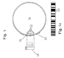
- FIG. 1 While in Fig. 1 an embodiment of the steering angle sensor is shown who works with incident light, 5 shows a sensor that works with transmitted light.
- a circular ring 54 in the area of the light lines a code 53 translucent.
- a light emitting diode 52 Inside the ring is a light emitting diode 52 and an optics 55 arranged. Both are outside the annulus Associated with photodetector line 51.
- the code 53 according to FIG. 5a corresponds to the code of FIG. 1a.
- the code track is in in this case illuminated with parallel light.
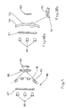
- Line sensors 65 and 66 can also be an area sensor 61 can be used for this function.
- FIG. 7a is a code 73 with two tracks 71, 72, as shown in FIG. 7a can be seen.
- Each of the two code tracks is with a line sensor 65, 66 or different lines of an area sensor 61 considered.
- the code of the second code track can now e.g. inverse to that of the first code track be so that by simply subtracting the measured values in the microcontroller 8 a simple control of the sensor input results.
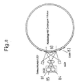
- FIG. 8 Another arrangement is shown in FIG. 8. to Increasing the sensor security is in this embodiment a second CCD sensor 85 horizontally next to the first CCD sensor 84 placed. Due to the horizontal arrangement are different code words at two different Set the code track 82 registered. The difference in Measurement results of both CCD sensors must be the differential viewing angle result of both photo detectors to the code track. This angle is due to the position of the CCD sensors known.
- a corresponding one can also be used larger linear CCD sensor can be used. Furthermore is the combination of two photo detector lines in an integrated circuit 81 with a common one Housing possible.
- one or more LEDs 86 directly or via a focusing screen 87 via a Optics 88 mapped onto a photodetector arrangement 89.
- the Coding consists of a ring 90, the translucent Angular ranges 91 and opaque angular ranges 92 through injected recesses or through accordingly translucent and opaque plastics be generated.
- a or several LEDs 86 directly or via the focusing screen 87 or Fresnel lens by means of an arrangement of the same type or differently designed cylindrical lenses 93 without further optics shown on the photodetector array 89.
- the cylinder lenses 93 produce stripes of different sizes Brightness on the photodetector array 89.
- a corresponding code is generated which is used for Scanning the steering angle is used.
- the arrangement of the cylindrical lenses is shown in Figure 10b.
- a coding ring 95 can be designed in this way be that he's out of a prismatic arrangement there is one or more LEDs 86 e.g. axially the Irradiate the arrangement (Fig. 11). The redirection of the light rays happens at the hypotenuse 95a of the prism.
- the radial light emission at the circumference of the coding ring 95 is so designed that there are quasi-flat surface areas 96 and Cylinder lens assemblies 93 are located.
- Through the plan A homogeneous light emission on the radial surface is created attached photodetector assembly 89. Through the cylindrical lenses 93 areas are created on the photodetector arrangement 89 low and high luminance.
- the coding for determining the steering angle is done by appropriate distribution of quasi plan areas and by the same or different designed cylindrical lenses.
- s 86 in a transparent Coding ring 97 radiated and this coding ring has a number of cylinders 98 on one end directly are connected to the coding ring and at the other end are either flat or lenticular. So that will a corresponding luminance on each of these cylinders occur, which is detected via the photodetector arrangement 89 can be. Through areas with and without cylinders and design a code can be applied to the density and accordingly can be detected.
- the arrangements can be designed in radial or axial form the direction of light passage in two possible directions can be selected.
- FIG. 13 there is no lens arrangement required.
- An almost point light source e.g. by using a laser diode 101 with a light emitting Area of e.g. 2 ⁇ x 3 ⁇ with the barrier layer e.g. parallel to the axis illuminates the coding ring 90, the from the translucent areas 91 and the opaque Areas 92 exists.
- Behind the coding ring 90 a linear photodetector arrangement 89 is provided, on which there is a luminance distribution in the translucent areas arises from the coding. This luminance distribution is evaluated.
- the arrangement according to Fig. 13 can by the application of two side by side, at a known distance Laser diodes 101 and 102 are improved, as shown in Fig. 14a and b.
- the evaluation is the same as for the embodiment of FIG. 13 described. Changes however, the radial distance of the coding ring 90 by radial Impact of the steering wheel or changes due to mechanical or thermal influences the distance of the components with each other, which is shown in FIG. 14a by items 1 and 2 the photodetector arrangement is indicated, so can by different shadowing of the two laser diodes 101 and 102, the distance of which remains constant, on the photodetector array 89 nevertheless the position and angular position of the code be accurately detected.
- the laser diodes 101 and 102 are excited in quick succession, with the Time is selected as short, e.g. 10 ⁇ s - 100 ⁇ s that in no change in angle restricting accuracy at this time occurs on the steering wheel.
- the Time is selected as short, e.g. 10 ⁇ s - 100 ⁇ s that in no change in angle restricting accuracy at this time occurs on the steering wheel.
- a monolithic LED in double or triple arrangement can be used for light-emitting surfaces with very small expansion in the axial direction appropriate masks are generated.
- FIG. 16 shows a combination an angle-determining code 105 with a reference code 106.
- the angle can be evaluated as well as via checked the reference code on the one hand the CCD or the photodecoder arrangement be, on the other hand about the known Distances of the reference code the distance and the exact Angles can be determined.
- the angle-determining code 105 can also be parallel to Reference code 106 can be applied as shown in FIG. 17 is shown. If the reference code 106, as shown here, applied at the top and bottom of the edge of the angle codes, so an axial tolerance affects the image the reference code 106.
- Both codes can be mapped together and by means of LEDs 86 are illuminated, as can be seen from FIG. 18.
- An angle signal can thus be sent to the photodetector arrangement 89 107 and reference signal 108 corresponding to FIG. 19 generated and evaluated.
Landscapes
- Physics & Mathematics (AREA)
- General Physics & Mathematics (AREA)
- Engineering & Computer Science (AREA)
- Chemical & Material Sciences (AREA)
- Combustion & Propulsion (AREA)
- Transportation (AREA)
- Mechanical Engineering (AREA)
- Length Measuring Devices By Optical Means (AREA)
- Transmission And Conversion Of Sensor Element Output (AREA)
- Optical Transform (AREA)
- Length Measuring Devices With Unspecified Measuring Means (AREA)
Claims (28)
- Détecteur d'angle de direction adaptatif absolu pour la détermination absolue d'un angle de braquage, en particulier pour l'établissement de l'angle de direction dans un véhicule au moyen d'un code (2) pour une zone d'angle de 360° afin d'établir l'angle; le code (2) et un dispositif de détection (7) étant disposés de façon pivotante l'un par rapport à l'autre ; une détermination absolue de l'angle ayant lieu par la lecture de l'information de contraste grâce à un microprocesseur qui établit aussi bien la situation de l'angle du code que la définition précise de l'angle par la situation relative du code reconnu pour obtenir une image sur le dispositif de photodétection ; le fonctionnement global du système étant en même temps vérifié et adapté lors de chaque mesure,
caractérisé en ce que
le code est établi au moyen d'un dispositif de photodétection placé à un seul endroit et qu'il est utifisé pour la détermination de l'angle, qu'un segment lié à la marque de code est représenté sur au moins une ligne du photodétecteur (7) - au moins un mot code correspondant à un angle prédéterminé étant saisi -, que la situation du mot code est mesurée en fonction de la position stable de la ligne du photodétecteur (7), que le code est représenté par un système optique (6) sur la ligne du photodétecteur (7) de sorte qu'avec un cycle de lecture des lignes d'une part on établit l'information absolue sur l'angle et d'autre part on vérifie et on adapte le fonctionnement global du système et qu'au moins une silhouette de référence est projetée sur la ligne du photodétecteur (7) pour contrôler les fonctions du système. - Détecteur d'angle de direction adaptatif absolu selon la revendication 1 caractérisé en ce que la mesure est réalisée au moyen d'un logiciel dans un microcontrôleur (8) qui utilise à cet effet les données image de la ligne du photodétecteur (7).
- Détecteur d'angle de direction adaptatif absolu selon la revendication 1 ou 2 caractérisé en ce que l'on représente au moins deux images différentes d'un ou de plusieurs codes périphériques sur la ligne du photodétecteur afin d'augmenter la résolution.
- Détecteur d'angle de direction adaptatif absolu selon au moins l'une des revendications précédentes caractérisé en ce que l'on utilise un mot code de 6 bits ou de 7 bits.
- Détecteur d'angle de direction adaptatif absolu selon au moins l'une des revendications précédentes caractérisé en ce que la marque de code est traversée par une lumière parallèle ou qu'elle est éclairée sur un des côtés.
- Détecteur d'angle de direction adaptatif absolu selon au moins l'une des revendications précédentes caractérisé en ce que l'on interprète la pente du signal et la dimension de l'image des signaux représentés sur la ligne du détecteur afin de compenser les tolérances optiques et mécaniques.
- Détecteur d'angle de direction adaptatif absolu selon au moins l'une des revendications précédentes caractérisé en ce que la zone d'angle prend une valeur entre 0° et 360° selon la vitesse du véhicule.
- Détecteur d'angle de direction adaptatif absolu selon au moins l'une des revendications précédentes caractérisé en ce que l'on établit l'angle de direction par un bref contact du détecteur d'angle de direction dans des intervalles de temps où il n'est pas possible que le braquage soit supérieur à 180° afin d'enregistrer l'angle absolu de direction même quand les systèmes du véhicule sont déconnectés.
- Détecteur d'angle adaptatif absolu selon au moins l'une des revendications précédentes caractérisé en ce que l'on a prévu au moins une source de lumière (4, 5) pour éclairer une zone d'angle (3) du code (2) et qu'on a prévu un dispositif de photodétection (7) pour enregistrer la zone d'angle (3) éclairée du code (2), un microcontrôleur étant lié à la source de lumière et au dispositif de photodétection.
- Détecteur d'angle adaptatif absolu selon la revendication 9 caractérisé en ce que l'on a placé symétriquement par rapport à l'axe optique deux diodes électroluminescentes (4, 5) comme sources de lumière, celles-ci ainsi que le dispositif de photodétection (7) et un système optique (6) étant placés sur le même côté de l'anneau de codage (1).
- Détecteur d'angle adaptatif absolu selon la revendication 9 caractérisé en ce que l'on a prévu un anneau de codage (54) circulaire translucide aux endroits éclairés du code et qu'on a placé sur l'un des côtés de l'anneau de codage au moins une diode électroluminescente (52) et sur l'autre côté de l'anneau de codage le dispositif de photodétection (51).
- Détecteur d'angle adaptatif absolu selon la revendication 11 caractérisé en ce que l'on a prévu un système optique (55) sur le côté de la diode électroluminescente (52).
- Détecteur d'angle adaptatif absolu selon au moins l'une des revendications précédentes caractérisé en ce que le dispositif de photodétection présente deux détecteurs (65, 66) placés verticalement l'un au-dessus de l'autre en fonction du trajet de la marque de code (62) pour permettre leur visualisation synchrone et que les images (67, 68) des deux détecteurs sont comparées l'une à l'autre.
- Détecteur d'angle adaptatif absolu selon la revendication 13 caractérisé en ce que l'on a prévu en tant que détecteurs deux détecteurs de lignes (65, 66) ou deux sections d'un détecteur de surface (61) placées l'une au-dessus de l'autre.
- Détecteur d'angle adaptatif absolu selon au moins l'une des revendications précédentes caractérisé en ce que deux détecteurs (84, 85) sont placés horizontalement l'un à côté de l'autre pour permettre l'enregistrement synchrone des mots code contigus de la marque de code (82).
- Détecteur d'angle adaptatif absolu selon au moins l'une des revendications précédentes caractérisé en ce qu'on a prévu comme détecteurs de lumière des dispositifs à couplage de charges (CCD).
- Détecteur d'angle adaptatif absolu selon au moins l'une des revendications précédentes caractérisé en ce que les lignes clair-obscur des mots code présentent une largeur de 2 à 3 mm.
- Détecteur d'angle adaptatif absolu selon au moins l'une des revendications précédentes caractérisé en ce qu'un verre dépoli (87) est placé entre la source de lumière (86) et l'anneau de codage (90) et que le système optique (88) et le dispositif de photodétection (89) sont prévus de l'autre côté de l'anneau de codage (90).
- Détecteur d'angle adaptatif absolu selon au moins l'une des revendications précédentes caractérisé en ce qu'un anneau de codage (94) transparent présente de place en place des lentilles cylindriques placées les unes à côté des autres à effet de produire le code et de représenter les sources de lumière (86) sur le dispositif de photodétection (89).
- Détecteur d'angle adaptatif absolu selon au moins l'une des revendications précédentes caractérisé en ce que l'anneau de codage (95) présente une section transversale prismatique - avec une source de lumière (86) rayonnant en direction axiale de l'anneau de codage.
- Détecteur d'angle adaptatif absolu selon au moins l'une des revendications 9 à 19 caractérisé en ce que l'on a prévu sur un anneau de codage (97) transparent de place en place des cylindres (98) ou des lentilles (99) placées les unes à côté des l'autres à effet de produire le code et de représenter les sources de lumière (86) sur le dispositif de photodétection (89) ; les cylindres s'étendent alors dans la direction axiale de l'anneau de codage, ils sont fixés à l'anneau de codage par une surface frontale et liés aux sources de lumière et ils sont liés au dispositif de photodétection (89) par leurs autres surfaces frontales libres.
- Détecteur d'angle adaptatif absolu selon la revendication 21 caractérisé en ce que les surfaces frontales libres des cylindres sont planes ou en forme de lentille.
- Détecteur d'angle adaptatif absolu selon au moins l'une des revendications précédentes caractérisé en ce qu'au moins une source de lumière (101, 102) ponctuelle est liée à l'anneau de codage (90) transparent qui présente des zones translucides (91) et des zones opaques (92).
- Détecteur d'angle adaptatif absolu selon la revendication 23 caractérisé en ce que l'on a prévu deux sources de lumière (101, 102) ponctuelles l'une à côté de l'autre à intervalles constants et un seul dispositif de photodétection (89).
- Détecteur d'angle adaptatif absolu selon la revendication 23 caractérisé en ce que l'on a prévu une source de lumière (101) ponctuelle et deux lignes de photodétection (103, 104) disposées l'une au-dessus de l'autre à intervalles variables par rapport à la source de lumière (101).
- Détecteur d'angle adaptatif absolu selon au moins l'une des revendications précédentes caractérisé en ce que sur l'anneau de codage au moins un code de référence (106) est lié au code (105) qui détermine l'angle.
- Détecteur d'angle adaptatif absolu selon la revendication 26 caractérisé en ce que le code de référence (106) est disposé à côté du code (105) qui détermine l'angle.
- Détecteur d'angle adaptatif absolu selon la revendication 26 caractérisé en ce que le code de référence (106) est prévu au-dessus et en dessous du code (105) qui détermine l'angle.
Applications Claiming Priority (3)
| Application Number | Priority Date | Filing Date | Title |
|---|---|---|---|
| DE1997158104 DE19758104B4 (de) | 1997-02-13 | 1997-12-18 | Adaptiver absoluter Lenkwinkelsensor |
| DE19758104 | 1997-12-18 | ||
| PCT/DE1998/003776 WO1999032345A1 (fr) | 1997-12-18 | 1998-12-17 | Detecteur adaptatif pour la determination absolue d'un angle de braquage |
Publications (2)
| Publication Number | Publication Date |
|---|---|
| EP1040039A1 EP1040039A1 (fr) | 2000-10-04 |
| EP1040039B1 true EP1040039B1 (fr) | 2002-03-27 |
Family
ID=7853519
Family Applications (1)
| Application Number | Title | Priority Date | Filing Date |
|---|---|---|---|
| EP98966577A Expired - Lifetime EP1040039B1 (fr) | 1997-12-18 | 1998-12-17 | Detecteur adaptatif pour la determination absolue d'un angle de braquage |
Country Status (7)
| Country | Link |
|---|---|
| US (1) | US6459389B1 (fr) |
| EP (1) | EP1040039B1 (fr) |
| JP (1) | JP3845549B2 (fr) |
| BR (1) | BR9813820A (fr) |
| DE (1) | DE59803570D1 (fr) |
| ES (1) | ES2177137T3 (fr) |
| WO (1) | WO1999032345A1 (fr) |
Cited By (2)
| Publication number | Priority date | Publication date | Assignee | Title |
|---|---|---|---|---|
| EP1345031A2 (fr) | 2002-03-16 | 2003-09-17 | Leuze electronic GmbH + Co. | Dispositif opto-électronique |
| DE102005047658A1 (de) * | 2005-10-05 | 2007-04-12 | Leuze Electronic Gmbh + Co. Kg | Vorrichtung zur Positionsbestimmung |
Families Citing this family (29)
| Publication number | Priority date | Publication date | Assignee | Title |
|---|---|---|---|---|
| DE10056605A1 (de) * | 2000-11-15 | 2002-05-23 | Kostal Leopold Gmbh & Co Kg | Verfahren zur Signalauswertung einer optoelektronischen Weg-oder Winkelmeßeinrichtung sowie Verwendung eines solchen Verfahrens |
| EP1389910A4 (fr) * | 2001-04-20 | 2005-11-02 | Lavipharm Lab Inc | Distribution intrabucale de nicotine destinee a arreter de fumer |
| JP4205343B2 (ja) * | 2002-01-15 | 2009-01-07 | アルプス電気株式会社 | 回転角検出装置 |
| US6844541B2 (en) * | 2002-02-15 | 2005-01-18 | Methode Electronics, Inc. | Rapid high resolution position sensor for auto steering |
| US6867412B2 (en) * | 2002-11-12 | 2005-03-15 | Mitutoyo Corporation | Scale structures and methods usable in an absolute position transducer |
| US7034283B2 (en) * | 2003-03-05 | 2006-04-25 | Raytheon Company | Absolute incremental position encoder and method |
| WO2004111577A2 (fr) * | 2003-06-11 | 2004-12-23 | S.N.R. Roulements | Determination de la position angulaire absolue d’un volant par discrimination de sequences binaires |
| FR2856142B1 (fr) * | 2003-06-11 | 2005-09-30 | Roulements Soc Nouvelle | Determination de la position angulaire absolue d'un volant par mesure incrementale et mesure de la vitesse differentielle des roues |
| FR2856147B1 (fr) * | 2003-06-11 | 2005-08-05 | Roulements Soc Nouvelle | Determination de la position angulaire absolue d'un volant par discrimination de sequences binaires |
| US7265336B2 (en) * | 2003-12-01 | 2007-09-04 | Avago Technologies Ecbu Ip (Singapore) Pte. Ltd. | Encoder utilizing a reflective cylindrical surface |
| US7763843B2 (en) * | 2004-03-01 | 2010-07-27 | Stanton Magnetics, Inc. | Optical navigation system for rotary control based non-contact controller |
| US7085638B2 (en) * | 2004-07-13 | 2006-08-01 | Robert Bosch Gmbh | Steering angle sensor assembly including reduction gear and logic module |
| DE102005032871A1 (de) * | 2005-07-14 | 2007-01-25 | Leopold Kostal Gmbh & Co. Kg | Verfahren zum Bestimmen der absoluten Winkelstellung des Lenkrades eines Kraftfahrzeugs |
| DE102005032869A1 (de) * | 2005-07-14 | 2007-01-25 | Leopold Kostal Gmbh & Co. Kg | Verfahren zum Bestimmen der absoluten Winkelstellung des Lenkrades eines Kraftfahrzeugs |
| DE102005032870A1 (de) * | 2005-07-14 | 2007-01-25 | Leopold Kostal Gmbh & Co. Kg | Verfahren zum Bestimmen der absoluten Winkelstellung des Lenkrades eines Kraftfahrzeugs |
| DE102005038855A1 (de) * | 2005-08-12 | 2007-02-15 | Takata-Petri Ag | Lenkradanordnung |
| DE102006061929A1 (de) * | 2006-12-20 | 2008-06-26 | Takata-Petri Ag | Optischer Lenkwinkelsensor zur Bestimmung des Absolutwertes des Lenkwinkels |
| US20080203283A1 (en) * | 2007-02-23 | 2008-08-28 | Yee Loong Chin | Optical encoder with detector lens |
| US8251291B2 (en) * | 2009-04-01 | 2012-08-28 | Honeywell International Inc. | Rotational bar code orientation sensor |
| JP5832088B2 (ja) * | 2010-12-15 | 2015-12-16 | キヤノン株式会社 | ロータリーエンコーダ |
| US20120283986A1 (en) * | 2011-05-03 | 2012-11-08 | Ashok Veeraraghavan | System and Method for Measuring Positions |
| DE102012209585A1 (de) * | 2012-06-06 | 2013-12-12 | Robert Bosch Gmbh | Sensoranordnung zur Erfassung von Drehwinkeln an einem rotierenden Bauteil |
| JP5787124B2 (ja) * | 2012-07-04 | 2015-09-30 | 株式会社安川電機 | エンコーダ及びサーボモータ |
| JP6149740B2 (ja) * | 2014-01-23 | 2017-06-21 | 三菱電機株式会社 | アブソリュートエンコーダ |
| US9841278B2 (en) * | 2015-09-30 | 2017-12-12 | Siemens Industry Software Nv | System and method for resolving information about a rotor comprising a measuring device for measuring and recording in a fixed rotor state without vibration due to rotation |
| JP5974154B2 (ja) * | 2015-10-28 | 2016-08-23 | キヤノン株式会社 | ロータリーエンコーダ |
| CN109141486B (zh) * | 2018-08-30 | 2021-07-27 | 济宁学院 | 电动汽车方向盘位置传感器 |
| DE102020002676B3 (de) * | 2020-05-05 | 2021-03-25 | Sew-Eurodrive Gmbh & Co Kg | Mobiles Transportsystem |
| US12372624B2 (en) * | 2021-03-24 | 2025-07-29 | Waymo Llc | Optical sensor for mirror zero angle in a scanning lidar |
Family Cites Families (9)
| Publication number | Priority date | Publication date | Assignee | Title |
|---|---|---|---|---|
| US4901073A (en) * | 1986-12-04 | 1990-02-13 | Regent Of The University Of California | Encoder for measuring the absolute position of moving elements |
| ES2030254T3 (es) | 1988-11-02 | 1992-10-16 | Daimler-Benz Aktiengesellschaft | Sensor del angulo de direccion de un vehiculo automovil. |
| JPH02248811A (ja) * | 1989-03-22 | 1990-10-04 | Fuji Heavy Ind Ltd | 車両用舵角センサの絶対舵角検出方法 |
| JPH0526688A (ja) | 1991-07-19 | 1993-02-02 | Furuno Electric Co Ltd | ロータリエンコーダ |
| GB9202868D0 (en) * | 1992-02-12 | 1992-03-25 | Lucas Ind Plc | Optical torque sensors and steering systems for vehicles incorporating them |
| NL9201059A (nl) * | 1992-06-15 | 1994-01-03 | Bootsman Holding Bv | Positiedetectiesysteem. |
| JP3412897B2 (ja) | 1994-02-18 | 2003-06-03 | 三菱電機株式会社 | アブソリュートエンコーダ |
| US6483104B1 (en) | 1996-09-23 | 2002-11-19 | Valeo Schalter Und Sensoren Gmbh | Rotational angle sensor using a CCD line with enhanced measuring precision |
| DE19705312B4 (de) | 1997-02-13 | 2009-04-16 | Takata-Petri Ag | Adaptiver Lenkwinkelsensor für Fahrzeuge |
-
1998
- 1998-12-17 BR BR9813820-0A patent/BR9813820A/pt not_active Application Discontinuation
- 1998-12-17 WO PCT/DE1998/003776 patent/WO1999032345A1/fr not_active Ceased
- 1998-12-17 DE DE59803570T patent/DE59803570D1/de not_active Expired - Lifetime
- 1998-12-17 US US09/581,968 patent/US6459389B1/en not_active Expired - Lifetime
- 1998-12-17 JP JP2000525296A patent/JP3845549B2/ja not_active Expired - Fee Related
- 1998-12-17 EP EP98966577A patent/EP1040039B1/fr not_active Expired - Lifetime
- 1998-12-17 ES ES98966577T patent/ES2177137T3/es not_active Expired - Lifetime
Cited By (4)
| Publication number | Priority date | Publication date | Assignee | Title |
|---|---|---|---|---|
| EP1345031A2 (fr) | 2002-03-16 | 2003-09-17 | Leuze electronic GmbH + Co. | Dispositif opto-électronique |
| EP1345031A3 (fr) * | 2002-03-16 | 2004-07-28 | Leuze electronic GmbH + Co. | Dispositif opto-électronique |
| DE102005047658A1 (de) * | 2005-10-05 | 2007-04-12 | Leuze Electronic Gmbh + Co. Kg | Vorrichtung zur Positionsbestimmung |
| DE102005047658B4 (de) * | 2005-10-05 | 2008-03-20 | Leuze Electronic Gmbh + Co. Kg | Vorrichtung zur Positionsbestimmung |
Also Published As
| Publication number | Publication date |
|---|---|
| ES2177137T3 (es) | 2002-12-01 |
| WO1999032345A1 (fr) | 1999-07-01 |
| DE59803570D1 (de) | 2002-05-02 |
| JP2001526401A (ja) | 2001-12-18 |
| US6459389B1 (en) | 2002-10-01 |
| BR9813820A (pt) | 2000-10-10 |
| JP3845549B2 (ja) | 2006-11-15 |
| EP1040039A1 (fr) | 2000-10-04 |
Similar Documents
| Publication | Publication Date | Title |
|---|---|---|
| EP1040039B1 (fr) | Detecteur adaptatif pour la determination absolue d'un angle de braquage | |
| DE19758104B4 (de) | Adaptiver absoluter Lenkwinkelsensor | |
| EP1947477B1 (fr) | Capteur de triangulation doté d'une détermination d'éloignement à partir de la position et de la forme de la tache lumineuse | |
| DE69806325T2 (de) | Winkelsensor der eine multi-pixel optische Vorrichtung verwendet | |
| EP2150780B1 (fr) | Procédé et dispositif optoélectronique de mesure de position | |
| DE102004048237A1 (de) | Codierer, der eine reflektierende zylindrische Oberfläche verwendet | |
| DE798567T1 (de) | Messvorrichtung zum Prüfen des Ortes eines Fahrzeuges und Sensor dafür | |
| EP2384296A1 (fr) | Système de caméra pour l'acquisition de l'état d'une vitre d'un véhicule | |
| EP0096152A2 (fr) | Capteur de position pour mécanisme d'entraînement, particulièrement pour véhicules | |
| EP2381222A1 (fr) | Système de guidage doté de corpsen déplacement relatif et dispositif de détermination d'une position à l'aide du balayage optique d'une échelle de mesure. | |
| DE29911390U1 (de) | Optoelektronisches Überwachungssystem | |
| DE19638911B4 (de) | Drehwinkelsensor mit integrierter Umdrehungserkennung | |
| EP1586866B1 (fr) | Procédé optoélectronique de déterminer la position d'un capteur pour compenser des erreurs d'ajustement | |
| DE2312588C3 (de) | Aufnahmekopf fur einen optischen Korrelations-Geschwindigkeitsmesser | |
| EP2808653B1 (fr) | Capteur d´angle de rotation | |
| DE112007002449T5 (de) | Codeumsetzer | |
| DE19705312B4 (de) | Adaptiver Lenkwinkelsensor für Fahrzeuge | |
| EP1857838B1 (fr) | Dispositif de protection optoélectrique | |
| DE102013007961A1 (de) | Optisches Messsystem für ein Fahrzeug | |
| EP2053868A1 (fr) | Capteur optoélectronique haute résolution doté d'une unité de test et procédé de test correspondant | |
| EP2513874A1 (fr) | Détecteur pour vérifier des documents de valeur | |
| EP2664897B1 (fr) | Encodeur et procédé destinés à la détermination d'une position angulaire | |
| DE19946220C1 (de) | Optoelektronische Sensoreinrichtung | |
| DE10004889B4 (de) | Verfahren und Vorrichtung zum optischen Erkennen von lokalen Verformungen, insbesondere Bläschen, in einem Gegenstand | |
| EP3392679B1 (fr) | Capteur optique |
Legal Events
| Date | Code | Title | Description |
|---|---|---|---|
| PUAI | Public reference made under article 153(3) epc to a published international application that has entered the european phase |
Free format text: ORIGINAL CODE: 0009012 |
|
| 17P | Request for examination filed |
Effective date: 20000619 |
|
| AK | Designated contracting states |
Kind code of ref document: A1 Designated state(s): DE ES FR GB |
|
| GRAG | Despatch of communication of intention to grant |
Free format text: ORIGINAL CODE: EPIDOS AGRA |
|
| 17Q | First examination report despatched |
Effective date: 20010531 |
|
| GRAG | Despatch of communication of intention to grant |
Free format text: ORIGINAL CODE: EPIDOS AGRA |
|
| GRAH | Despatch of communication of intention to grant a patent |
Free format text: ORIGINAL CODE: EPIDOS IGRA |
|
| RAP1 | Party data changed (applicant data changed or rights of an application transferred) |
Owner name: TAKATA-PETRI AG |
|
| GRAH | Despatch of communication of intention to grant a patent |
Free format text: ORIGINAL CODE: EPIDOS IGRA |
|
| REG | Reference to a national code |
Ref country code: GB Ref legal event code: IF02 |
|
| GRAA | (expected) grant |
Free format text: ORIGINAL CODE: 0009210 |
|
| AK | Designated contracting states |
Kind code of ref document: B1 Designated state(s): DE ES FR GB |
|
| REF | Corresponds to: |
Ref document number: 59803570 Country of ref document: DE Date of ref document: 20020502 |
|
| GBT | Gb: translation of ep patent filed (gb section 77(6)(a)/1977) |
Effective date: 20020614 |
|
| ET | Fr: translation filed | ||
| REG | Reference to a national code |
Ref country code: ES Ref legal event code: FG2A Ref document number: 2177137 Country of ref document: ES Kind code of ref document: T3 |
|
| PLBE | No opposition filed within time limit |
Free format text: ORIGINAL CODE: 0009261 |
|
| STAA | Information on the status of an ep patent application or granted ep patent |
Free format text: STATUS: NO OPPOSITION FILED WITHIN TIME LIMIT |
|
| 26N | No opposition filed |
Effective date: 20021230 |
|
| PGFP | Annual fee paid to national office [announced via postgrant information from national office to epo] |
Ref country code: FR Payment date: 20081212 Year of fee payment: 11 Ref country code: ES Payment date: 20090120 Year of fee payment: 11 |
|
| PGFP | Annual fee paid to national office [announced via postgrant information from national office to epo] |
Ref country code: GB Payment date: 20081217 Year of fee payment: 11 |
|
| GBPC | Gb: european patent ceased through non-payment of renewal fee |
Effective date: 20091217 |
|
| REG | Reference to a national code |
Ref country code: FR Ref legal event code: ST Effective date: 20100831 |
|
| PG25 | Lapsed in a contracting state [announced via postgrant information from national office to epo] |
Ref country code: FR Free format text: LAPSE BECAUSE OF NON-PAYMENT OF DUE FEES Effective date: 20091231 |
|
| PG25 | Lapsed in a contracting state [announced via postgrant information from national office to epo] |
Ref country code: GB Free format text: LAPSE BECAUSE OF NON-PAYMENT OF DUE FEES Effective date: 20091217 |
|
| REG | Reference to a national code |
Ref country code: ES Ref legal event code: FD2A Effective date: 20110411 |
|
| PG25 | Lapsed in a contracting state [announced via postgrant information from national office to epo] |
Ref country code: ES Free format text: LAPSE BECAUSE OF NON-PAYMENT OF DUE FEES Effective date: 20110329 |
|
| PG25 | Lapsed in a contracting state [announced via postgrant information from national office to epo] |
Ref country code: ES Free format text: LAPSE BECAUSE OF NON-PAYMENT OF DUE FEES Effective date: 20091218 |
|
| REG | Reference to a national code |
Ref country code: DE Ref legal event code: R082 Ref document number: 59803570 Country of ref document: DE Representative=s name: MAIKOWSKI & NINNEMANN PATENTANWAELTE, DE |
|
| REG | Reference to a national code |
Ref country code: DE Ref legal event code: R082 Ref document number: 59803570 Country of ref document: DE Representative=s name: MAIKOWSKI & NINNEMANN PATENTANWAELTE PARTNERSC, DE Effective date: 20120904 Ref country code: DE Ref legal event code: R082 Ref document number: 59803570 Country of ref document: DE Representative=s name: MAIKOWSKI & NINNEMANN PATENTANWAELTE, DE Effective date: 20120904 Ref country code: DE Ref legal event code: R081 Ref document number: 59803570 Country of ref document: DE Owner name: TAKATA AKTIENGESELLSCHAFT, DE Free format text: FORMER OWNER: TAKATA-PETRI AG, 63743 ASCHAFFENBURG, DE Effective date: 20120904 |
|
| PGFP | Annual fee paid to national office [announced via postgrant information from national office to epo] |
Ref country code: DE Payment date: 20141209 Year of fee payment: 17 |
|
| REG | Reference to a national code |
Ref country code: DE Ref legal event code: R119 Ref document number: 59803570 Country of ref document: DE |
|
| PG25 | Lapsed in a contracting state [announced via postgrant information from national office to epo] |
Ref country code: DE Free format text: LAPSE BECAUSE OF NON-PAYMENT OF DUE FEES Effective date: 20160701 |