EP1040232B1 - Verstelleinrichtung für ein bewegliches arbeitsgerät einer mobilen arbeitsmaschine - Google Patents
Verstelleinrichtung für ein bewegliches arbeitsgerät einer mobilen arbeitsmaschine Download PDFInfo
- Publication number
- EP1040232B1 EP1040232B1 EP98945212A EP98945212A EP1040232B1 EP 1040232 B1 EP1040232 B1 EP 1040232B1 EP 98945212 A EP98945212 A EP 98945212A EP 98945212 A EP98945212 A EP 98945212A EP 1040232 B1 EP1040232 B1 EP 1040232B1
- Authority
- EP
- European Patent Office
- Prior art keywords
- adjustment device
- anvil
- lifting frame
- wedge
- stop
- Prior art date
- Legal status (The legal status is an assumption and is not a legal conclusion. Google has not performed a legal analysis and makes no representation as to the accuracy of the status listed.)
- Expired - Lifetime
Links
- 230000001105 regulatory effect Effects 0.000 title abstract 3
- 229910000760 Hardened steel Inorganic materials 0.000 claims description 2
- 238000006073 displacement reaction Methods 0.000 description 3
- 229910000831 Steel Inorganic materials 0.000 description 1
- 230000008901 benefit Effects 0.000 description 1
- 239000000969 carrier Substances 0.000 description 1
- 238000010276 construction Methods 0.000 description 1
- 230000000694 effects Effects 0.000 description 1
- 230000006872 improvement Effects 0.000 description 1
- 238000009434 installation Methods 0.000 description 1
- 230000003993 interaction Effects 0.000 description 1
- 238000000034 method Methods 0.000 description 1
- 230000008569 process Effects 0.000 description 1
- 230000009467 reduction Effects 0.000 description 1
- 238000005096 rolling process Methods 0.000 description 1
- 239000010959 steel Substances 0.000 description 1
- 238000003466 welding Methods 0.000 description 1
Images



Classifications
-
- E—FIXED CONSTRUCTIONS
- E02—HYDRAULIC ENGINEERING; FOUNDATIONS; SOIL SHIFTING
- E02F—DREDGING; SOIL-SHIFTING
- E02F3/00—Dredgers; Soil-shifting machines
- E02F3/04—Dredgers; Soil-shifting machines mechanically-driven
- E02F3/28—Dredgers; Soil-shifting machines mechanically-driven with digging tools mounted on a dipper- or bucket-arm, i.e. there is either one arm or a pair of arms, e.g. dippers, buckets
- E02F3/34—Dredgers; Soil-shifting machines mechanically-driven with digging tools mounted on a dipper- or bucket-arm, i.e. there is either one arm or a pair of arms, e.g. dippers, buckets with bucket-arms, i.e. a pair of arms, e.g. manufacturing processes, form, geometry, material of bucket-arms directly pivoted on the frames of tractors or self-propelled machines
- E02F3/3405—Dredgers; Soil-shifting machines mechanically-driven with digging tools mounted on a dipper- or bucket-arm, i.e. there is either one arm or a pair of arms, e.g. dippers, buckets with bucket-arms, i.e. a pair of arms, e.g. manufacturing processes, form, geometry, material of bucket-arms directly pivoted on the frames of tractors or self-propelled machines and comprising an additional linkage mechanism
- E02F3/3411—Dredgers; Soil-shifting machines mechanically-driven with digging tools mounted on a dipper- or bucket-arm, i.e. there is either one arm or a pair of arms, e.g. dippers, buckets with bucket-arms, i.e. a pair of arms, e.g. manufacturing processes, form, geometry, material of bucket-arms directly pivoted on the frames of tractors or self-propelled machines and comprising an additional linkage mechanism of the Z-type
-
- E—FIXED CONSTRUCTIONS
- E02—HYDRAULIC ENGINEERING; FOUNDATIONS; SOIL SHIFTING
- E02F—DREDGING; SOIL-SHIFTING
- E02F3/00—Dredgers; Soil-shifting machines
- E02F3/04—Dredgers; Soil-shifting machines mechanically-driven
- E02F3/28—Dredgers; Soil-shifting machines mechanically-driven with digging tools mounted on a dipper- or bucket-arm, i.e. there is either one arm or a pair of arms, e.g. dippers, buckets
- E02F3/36—Component parts
- E02F3/40—Dippers; Buckets ; Grab devices, e.g. manufacturing processes for buckets, form, geometry or material of buckets
- E02F3/401—Buckets or forks comprising, for example, shock absorbers, supports or load striking scrapers to prevent overload
Definitions
- the invention relates to an adjusting device for a movable Working device of a mobile working machine, in particular for a shovel of a wheel loader or the like, with a lifting frame and a tipping rod as well as with several Limit stops for the implement and the boom, wherein at least one stop is wedge-shaped and in and is slidably mounted against the wedge direction, such that that the stop is adjustable.
- end positions of the bucket are limited by stops, to defined positions of the bucket and the lever of the To adhere to the tilting linkage and to avoid undesired angular positions to avoid the lever.
- stop will usually produced by welded steel plates, when using the working machine on parts of the lifting frame attacks.
- a stop is provided, the two opposite Has wedge surfaces with different inclinations.
- This stop is arranged rotatable about a pin, such that that the attack either with one or with the other wedge surface can be brought into operative position.
- Such an adjustment device can be the stop bring in two different active positions that The disadvantages described can be overcome with such a However, do not fix the adjustment device either, because an adjustment to the respective installation conditions or wear the stop surfaces is not possible because only two setting options by turning the Are given.
- a generic adjustment device is from US-A-5,064,339 known. This adjustment device has a and wedge-shaped stop displaceable against the wedge direction on whose type of attachment and adjustment and in particular any readjustment, however, still needs improvement is.
- the object of the invention is such an adjustment device to evolve so that a simpler and safer and easily adjustable system for adjustment the attacks are provided.
- This task is done with an adjustment device at the beginning designated type solved according to the invention in that the stop of a wedge-shaped anvil with sliding Anvil carrier is formed, the anvil carrier with Mounting slots for sliding mounting a sliding surface of one on the linkage, lifting frame and / or implement arranged screw block is provided, and the wedge angle between the incline of the anvil and the sliding surface is chosen so that self-locking on the sliding surface is generated.
- only one stop on the implement is adjustable. This is with hoist constructions feasible where a third stop is not required is. A stop of the implement can on the implement welded and only the second stop adjustable his. Both stops are then on the lifting frame at the same time on. Alternatively, it can also be provided that only the stop for the limit of the rocker arm travel is adjustable. This is enough when the blade stops are welded in as well as the lifting frame spars are processed. A simultaneous The concern of the three stops is then guaranteed.
- the facing surfaces of the anvil carrier and the screw-on block are, and / or that the stops on the blade between the bearing plates are attached.
- the rocker arm stop is preferably attached to the lifting frame traverse.
- stops below the are advantageous Blade pivot point and an anvil is arranged such that it strikes directly on the lifting frame.
- the anvil is preferably made of non-hardened steel and its strength is equal to or less than that of the lifting frame. If two stops are provided on the implement are, it can be provided that only one adjustable is.
- FIG 1 is an example of a mobile machine a wheel loader 1 is shown.
- This wheel loader has one Shovel 5, which has an adjustment device in itself is connected to the wheel loader 1 in a known manner.
- This adjustment device has a lifting frame 2, a rocker arm 3 and a tilt rod 4.
- the end positions of the bucket 5 in the wheel loader 1 are determined by stops limited to defined positions of the blade and the Adhere to levers and undesirable angular positions of the levers to avoid. So it is with a wheel loader 1 e.g. required, in the tipping position with the path of the bucket 5 two stops and the way of the rocker arm 3 with one stop to limit.
- a wheel loader 1 e.g. required, in the tipping position with the path of the bucket 5 two stops and the way of the rocker arm 3 with one stop to limit.
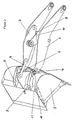
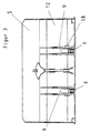
- To limit the shovel path is a right stop 6 and a left stop on the blade 5 Stop 7 in the manner described in more detail below arranged on the blade 5, the right stop 6 on right and left stop 7 strikes the left lifting frame spar.
- the rocker arm stop 8 sits centrally on a lifting frame cross member 10 of the lifting frame 2 and limits the rocker arm travel.
- the blade pivot point is designated by 18 in FIG.
- a stop is according to the invention from a wedge-shaped anvil 15 with a displaceable anvil carrier 17 formed.
- the anvil carrier has 17 mounting slots 14 on that for sliding attachment on a sliding surface 11 on the linkage, lifting frame 2 and / or the screw 5 arranged on the blade 5 are provided, with 13 fastening screws in the screw-on block 16 can be screwed in and an exact positioning of the wedge-shaped anvil 15 by appropriate Displacement of the anvil carrier 17 relative to the fastening screws 16 is possible.
- the appropriately designed stops 6 and 7 are on the right and left between the vane bearings 9 machined screw-on blocks 13 with threaded holes.
- the loading shovel 5 is so far tipped out until the rocker arm 3 at the stop 8 (on the lifting frame crossbar 10) is present.
- the stops are fastened by means of the fastening screws 16, whereby, as mentioned, through the elongated holes 14 in the Anvil carriers 17 can be screwed on in different positions are. Tolerances between the bars and the contact surfaces can be compensated for on the blade 5.
- the angle ⁇ of the stops 6, 7, 8 is so stated that he is within the self-locking range (approx. 14 °).
Landscapes
- Engineering & Computer Science (AREA)
- Mechanical Engineering (AREA)
- Mining & Mineral Resources (AREA)
- Civil Engineering (AREA)
- General Engineering & Computer Science (AREA)
- Structural Engineering (AREA)
- Shovels (AREA)
- Soil Working Implements (AREA)
- Lifting Devices For Agricultural Implements (AREA)
Description
- Fig. 1
- eine Seitenansicht eines Radladers,
- Fig. 2
- eine perspektivische Darstellung der Verstelleinrichtung mit Schaufel,
- Fig. 3
- eine Draufsicht auf die Schaufel der Verstelleinrichtung,
- Fig. 4
- eine Darstellung der Schaufel im Anlenkbereich an das Gestänge und
- Fig. 5
- eine vergrößerte perspektivische Darstellung der Befestigung eines Anschlages.
Claims (8)
- Verstelleinrichtung für ein bewegliches Arbeitsgerät (5) einer mobilen Arbeitsmaschine, insbesondere für eine Schaufel eines Radladers (1) oder dergl., mit einem Hubrahmen und einem Kippgestänge (3,4) sowie mit mehreren Endlagenanschlägen (6,7,8) für das Arbeitsgerät (5) und das Gestänge (3,4), wobei wenigstens ein Anschlag (6,7,8) keilförmig ausgebildet und in und gegen die Keilrichtung verschiebbar befestigt ist, derart, dass der Anschlag (6,7,8) einstellbar ist,
dadurch gekennzeichnet, dass der Anschlag (6,7,8) von einem keilförmigen Amboss (15) mit verschiebbarem Ambossträger (17) gebildet ist, wobei der Ambossträger (17) mit Befestigungslanglöchern (14) zur verschiebbaren Befestigung auf einer Gleitfläche (11) eines am Gestänge (3), Hubrahmen (2) und/oder Arbeitsgerät (5) angeordneten Anschraubklotzes (13) versehen ist, und wobei der Keilwinkel (α) zwischen der Neigung des Ambosses (15) und der Gleitfläche (11) derart gewählt ist, dass Selbsthemmung auf der Gleitfläche (11) erzeugt wird. - Verstelleinrichtung nach Anspruch 1,
dadurch gekennzeichnet, dass die zugewandten Oberflächen des Ambossträgers (17) und des Anschraubklotzes (13) bearbeitet sind. - Verstelleinrichtung nach Anspruch 1 oder 2,
dadurch gekennzeichnet, dass die Anschläge (6,7) am Arbeitsgerät (5) zwischen Lagerblechen (9) angebracht sind. - Verstelleinrichtung nach Anspruch 1 oder einem der folgenden,
dadurch gekennzeichnet, dass der Kipphebelanschlag (8) auf der Hubrahmentraverse (10) angebracht ist. - Verstelleinrichtung nach Anspruch 1 oder einem der folgenden,
dadurch gekennzeichnet, dass die Anschläge (6,7) unterhalb des Schaufeldrehpunktes (18) angeordnet sind. - Verstelleinrichtung nach Anspruch 1 oder einem der folgenden,
dadurch gekennzeichnet, dass ein Amboss (8) derart angeordnet ist, dass er direkt am Hubrahmen (10) anschlägt. - Verstelleinrichtung nach Anspruch 1 oder einem der folgenden,
dadurch gekennzeichnet, dass der Amboss (8) aus nicht gehärtetem Stahl besteht und seine Festigkeit gleich oder geringer als die des Hubrahmens (2) ist. - Verstelleinrichtung nach Anspruch 1 oder einem der folgenden,
dadurch gekennzeichnet, dass am Arbeitsgerät (5) zwei Anschläge (6,7) vorgesehen sind, von denen nur einer einstellbar ausgebildet ist.
Applications Claiming Priority (3)
| Application Number | Priority Date | Filing Date | Title |
|---|---|---|---|
| DE19755616A DE19755616C1 (de) | 1997-12-13 | 1997-12-13 | Verstelleinrichtung für ein bewegliches Arbeitsgerät einer mobilen Arbeitsmaschine |
| DE19755616 | 1997-12-13 | ||
| PCT/EP1998/005090 WO1999031327A1 (de) | 1997-12-13 | 1998-08-12 | Verstelleinrichtung für ein bewegliches arbeitsgerät einer mobilen arbeitsmaschine |
Publications (2)
| Publication Number | Publication Date |
|---|---|
| EP1040232A1 EP1040232A1 (de) | 2000-10-04 |
| EP1040232B1 true EP1040232B1 (de) | 2002-02-06 |
Family
ID=7851918
Family Applications (1)
| Application Number | Title | Priority Date | Filing Date |
|---|---|---|---|
| EP98945212A Expired - Lifetime EP1040232B1 (de) | 1997-12-13 | 1998-08-12 | Verstelleinrichtung für ein bewegliches arbeitsgerät einer mobilen arbeitsmaschine |
Country Status (4)
| Country | Link |
|---|---|
| EP (1) | EP1040232B1 (de) |
| AT (1) | ATE213038T1 (de) |
| DE (2) | DE19755616C1 (de) |
| WO (1) | WO1999031327A1 (de) |
Families Citing this family (2)
| Publication number | Priority date | Publication date | Assignee | Title |
|---|---|---|---|---|
| DE102007048330A1 (de) * | 2007-10-09 | 2009-04-23 | Agco Gmbh | Nutzfahrzeug mit einem Anschlagelement für einen Frontlader |
| PL223046B1 (pl) * | 2011-08-31 | 2016-10-31 | Przemysłowy Inst Masz Rolniczych | Układ zawieszenia narzędzi roboczych przednich w urządzeniu melioracyjnym |
Family Cites Families (5)
| Publication number | Priority date | Publication date | Assignee | Title |
|---|---|---|---|---|
| DE1118097B (de) * | 1956-09-15 | 1961-11-23 | Brown Tractors Ltd | Wahlweise als Frontlader oder UEberkopflader verwendbare Ladevorrichtung fuer Kraftfahrzeuge |
| GB825331A (en) * | 1957-02-11 | 1959-12-16 | Gen Motors Corp | Improvements in or relating to material handling apparatus |
| DE1913236A1 (de) * | 1968-03-18 | 1970-02-05 | Bofors Ab | Vorrichtung bei Schaufeln fuer Verlademaschinen |
| US3867750A (en) * | 1973-09-27 | 1975-02-25 | Clark Equipment Co | Machinery stop and method of installation |
| US5064339A (en) * | 1991-01-02 | 1991-11-12 | Deere & Company | Backhoe boom lock |
-
1997
- 1997-12-13 DE DE19755616A patent/DE19755616C1/de not_active Expired - Fee Related
-
1998
- 1998-08-12 WO PCT/EP1998/005090 patent/WO1999031327A1/de not_active Ceased
- 1998-08-12 AT AT98945212T patent/ATE213038T1/de not_active IP Right Cessation
- 1998-08-12 DE DE59803042T patent/DE59803042D1/de not_active Expired - Fee Related
- 1998-08-12 EP EP98945212A patent/EP1040232B1/de not_active Expired - Lifetime
Also Published As
| Publication number | Publication date |
|---|---|
| ATE213038T1 (de) | 2002-02-15 |
| WO1999031327A1 (de) | 1999-06-24 |
| DE59803042D1 (de) | 2002-03-21 |
| EP1040232A1 (de) | 2000-10-04 |
| DE19755616C1 (de) | 1999-06-02 |
Similar Documents
| Publication | Publication Date | Title |
|---|---|---|
| EP0464192B1 (de) | Schnellkupplung eines arbeitsvorsatzes an baggern | |
| DE69423972T2 (de) | Endabschnitt eines rahmenteils für ein fahrzeug | |
| DE3332022C2 (de) | ||
| DE10129292B4 (de) | Nahtschweißvorrichtung und Nahtschweißverfahren | |
| EP0666131B1 (de) | Schere für schwere Beanspruchungen, insbesondere Abbruch- bzw. Schrottschere | |
| DE60000575T2 (de) | Spannvorrichtung | |
| DE2444288C2 (de) | Verfahren zur Schaffung eines justierbaren Anschlages zwischen zwei Maschinenteilen und dazu geeigneter Anschlagkörper | |
| EP4663582A1 (de) | Spannbare bandfördervorrichtung mit robuster spannvorrichtung | |
| DE69407755T2 (de) | Backenbrecher mit freitragender brechschwinge | |
| EP1245740B1 (de) | Baufahrzeug mit einem Arbeitsgerät | |
| EP4028599B1 (de) | Greifer | |
| AT507412B1 (de) | Biegepresse mit stützlagervorrichtung für antriebsmittel | |
| EP1040232B1 (de) | Verstelleinrichtung für ein bewegliches arbeitsgerät einer mobilen arbeitsmaschine | |
| DE69531208T2 (de) | Stahlschneidvorrichtung mit polygonalen Messern | |
| DE102020130932A1 (de) | Anordnung zum Aufschweißen eines Folienpakets auf eine Stromableiterschiene einer Batteriezelle | |
| DE4117949A1 (de) | Mechanische ueberlastsicherung fuer beet- und drehpfluege | |
| AT395877B (de) | Einrichtung zum aufrauhen und einebnen einer mit hartschnee bedeckten und/oder vereisten verkehrsflaeche | |
| DE69423739T2 (de) | Pflugbalken | |
| DE29703678U1 (de) | Pistenpflegevorrichtung | |
| EP0437557B1 (de) | Planierschaufel | |
| DE202019004950U1 (de) | Flächen-Bearbeitungseinrichtung für eine Zugmaschine | |
| EP4012102B1 (de) | Heckfräse für eine pistenraupe | |
| DE2528208A1 (de) | Stabeisenschere | |
| EP0580978A1 (de) | Schneepflug | |
| DE102004042126A1 (de) | Sicherheitsstütze für Hubzylinder |
Legal Events
| Date | Code | Title | Description |
|---|---|---|---|
| PUAI | Public reference made under article 153(3) epc to a published international application that has entered the european phase |
Free format text: ORIGINAL CODE: 0009012 |
|
| 17P | Request for examination filed |
Effective date: 20000506 |
|
| AK | Designated contracting states |
Kind code of ref document: A1 Designated state(s): AT DE FR GB IT SE |
|
| GRAG | Despatch of communication of intention to grant |
Free format text: ORIGINAL CODE: EPIDOS AGRA |
|
| 17Q | First examination report despatched |
Effective date: 20010509 |
|
| GRAG | Despatch of communication of intention to grant |
Free format text: ORIGINAL CODE: EPIDOS AGRA |
|
| GRAH | Despatch of communication of intention to grant a patent |
Free format text: ORIGINAL CODE: EPIDOS IGRA |
|
| GRAH | Despatch of communication of intention to grant a patent |
Free format text: ORIGINAL CODE: EPIDOS IGRA |
|
| RAP1 | Party data changed (applicant data changed or rights of an application transferred) |
Owner name: O & K ORENSTEIN & KOPPEL AG |
|
| GRAA | (expected) grant |
Free format text: ORIGINAL CODE: 0009210 |
|
| REG | Reference to a national code |
Ref country code: GB Ref legal event code: IF02 |
|
| AK | Designated contracting states |
Kind code of ref document: B1 Designated state(s): AT DE FR GB IT SE |
|
| REF | Corresponds to: |
Ref document number: 213038 Country of ref document: AT Date of ref document: 20020215 Kind code of ref document: T |
|
| GBT | Gb: translation of ep patent filed (gb section 77(6)(a)/1977) |
Effective date: 20020206 |
|
| REF | Corresponds to: |
Ref document number: 59803042 Country of ref document: DE Date of ref document: 20020321 |
|
| ET | Fr: translation filed | ||
| PLBE | No opposition filed within time limit |
Free format text: ORIGINAL CODE: 0009261 |
|
| STAA | Information on the status of an ep patent application or granted ep patent |
Free format text: STATUS: NO OPPOSITION FILED WITHIN TIME LIMIT |
|
| 26N | No opposition filed |
Effective date: 20021107 |
|
| PGFP | Annual fee paid to national office [announced via postgrant information from national office to epo] |
Ref country code: GB Payment date: 20060627 Year of fee payment: 9 |
|
| PGFP | Annual fee paid to national office [announced via postgrant information from national office to epo] |
Ref country code: FR Payment date: 20060710 Year of fee payment: 9 |
|
| PGFP | Annual fee paid to national office [announced via postgrant information from national office to epo] |
Ref country code: DE Payment date: 20060713 Year of fee payment: 9 |
|
| PGFP | Annual fee paid to national office [announced via postgrant information from national office to epo] |
Ref country code: AT Payment date: 20060818 Year of fee payment: 9 |
|
| PGFP | Annual fee paid to national office [announced via postgrant information from national office to epo] |
Ref country code: IT Payment date: 20060831 Year of fee payment: 9 |
|
| PGFP | Annual fee paid to national office [announced via postgrant information from national office to epo] |
Ref country code: SE Payment date: 20060810 Year of fee payment: 9 |
|
| EUG | Se: european patent has lapsed | ||
| GBPC | Gb: european patent ceased through non-payment of renewal fee |
Effective date: 20070812 |
|
| PG25 | Lapsed in a contracting state [announced via postgrant information from national office to epo] |
Ref country code: SE Free format text: LAPSE BECAUSE OF NON-PAYMENT OF DUE FEES Effective date: 20070813 |
|
| PG25 | Lapsed in a contracting state [announced via postgrant information from national office to epo] |
Ref country code: AT Free format text: LAPSE BECAUSE OF NON-PAYMENT OF DUE FEES Effective date: 20070812 |
|
| REG | Reference to a national code |
Ref country code: FR Ref legal event code: ST Effective date: 20080430 |
|
| PG25 | Lapsed in a contracting state [announced via postgrant information from national office to epo] |
Ref country code: DE Free format text: LAPSE BECAUSE OF NON-PAYMENT OF DUE FEES Effective date: 20080301 |
|
| PG25 | Lapsed in a contracting state [announced via postgrant information from national office to epo] |
Ref country code: FR Free format text: LAPSE BECAUSE OF NON-PAYMENT OF DUE FEES Effective date: 20070831 |
|
| PG25 | Lapsed in a contracting state [announced via postgrant information from national office to epo] |
Ref country code: GB Free format text: LAPSE BECAUSE OF NON-PAYMENT OF DUE FEES Effective date: 20070812 |
|
| PG25 | Lapsed in a contracting state [announced via postgrant information from national office to epo] |
Ref country code: IT Free format text: LAPSE BECAUSE OF NON-PAYMENT OF DUE FEES Effective date: 20070812 |