EP1040243B1 - Elektrische steuerungsvorrichtung zur entriegelung einer drehenden welle, insbesondere eines schlosses und schloss mit solcher vorrichtung - Google Patents
Elektrische steuerungsvorrichtung zur entriegelung einer drehenden welle, insbesondere eines schlosses und schloss mit solcher vorrichtung Download PDFInfo
- Publication number
- EP1040243B1 EP1040243B1 EP98962472A EP98962472A EP1040243B1 EP 1040243 B1 EP1040243 B1 EP 1040243B1 EP 98962472 A EP98962472 A EP 98962472A EP 98962472 A EP98962472 A EP 98962472A EP 1040243 B1 EP1040243 B1 EP 1040243B1
- Authority
- EP
- European Patent Office
- Prior art keywords
- strut
- nut
- rotating shaft
- counter
- lever
- Prior art date
- Legal status (The legal status is an assumption and is not a legal conclusion. Google has not performed a legal analysis and makes no representation as to the accuracy of the status listed.)
- Expired - Lifetime
Links
- 230000009471 action Effects 0.000 claims description 4
- 238000001514 detection method Methods 0.000 claims description 4
- 210000000056 organ Anatomy 0.000 description 4
- 230000000903 blocking effect Effects 0.000 description 3
- 238000006073 displacement reaction Methods 0.000 description 3
- 230000000712 assembly Effects 0.000 description 2
- 238000000429 assembly Methods 0.000 description 2
- 230000008901 benefit Effects 0.000 description 2
- 230000008878 coupling Effects 0.000 description 2
- 238000010168 coupling process Methods 0.000 description 2
- 238000005859 coupling reaction Methods 0.000 description 2
- 230000007547 defect Effects 0.000 description 2
- 238000010586 diagram Methods 0.000 description 2
- 230000007257 malfunction Effects 0.000 description 2
- GUGOEEXESWIERI-UHFFFAOYSA-N Terfenadine Chemical compound C1=CC(C(C)(C)C)=CC=C1C(O)CCCN1CCC(C(O)(C=2C=CC=CC=2)C=2C=CC=CC=2)CC1 GUGOEEXESWIERI-UHFFFAOYSA-N 0.000 description 1
- 240000008042 Zea mays Species 0.000 description 1
- 238000004140 cleaning Methods 0.000 description 1
- 230000005672 electromagnetic field Effects 0.000 description 1
- 238000005265 energy consumption Methods 0.000 description 1
- 230000003100 immobilizing effect Effects 0.000 description 1
- 230000010354 integration Effects 0.000 description 1
- 238000012423 maintenance Methods 0.000 description 1
- 238000004519 manufacturing process Methods 0.000 description 1
- 230000007246 mechanism Effects 0.000 description 1
- 239000002184 metal Substances 0.000 description 1
- 238000012986 modification Methods 0.000 description 1
- 230000004048 modification Effects 0.000 description 1
- 230000008520 organization Effects 0.000 description 1
- 230000002028 premature Effects 0.000 description 1
- 230000035939 shock Effects 0.000 description 1
- 238000004804 winding Methods 0.000 description 1
Images




Classifications
-
- E—FIXED CONSTRUCTIONS
- E05—LOCKS; KEYS; WINDOW OR DOOR FITTINGS; SAFES
- E05B—LOCKS; ACCESSORIES THEREFOR; HANDCUFFS
- E05B47/00—Operating or controlling locks or other fastening devices by electric or magnetic means
- E05B47/06—Controlling mechanically-operated bolts by electro-magnetically-operated detents
- E05B47/0657—Controlling mechanically-operated bolts by electro-magnetically-operated detents by locking the handle, spindle, follower or the like
- E05B47/0665—Controlling mechanically-operated bolts by electro-magnetically-operated detents by locking the handle, spindle, follower or the like radially
- E05B47/0669—Controlling mechanically-operated bolts by electro-magnetically-operated detents by locking the handle, spindle, follower or the like radially with a pivotally moveable blocking element
-
- E—FIXED CONSTRUCTIONS
- E05—LOCKS; KEYS; WINDOW OR DOOR FITTINGS; SAFES
- E05B—LOCKS; ACCESSORIES THEREFOR; HANDCUFFS
- E05B15/00—Other details of locks; Parts for engagement by bolts of fastening devices
- E05B15/004—Lost motion connections
-
- E—FIXED CONSTRUCTIONS
- E05—LOCKS; KEYS; WINDOW OR DOOR FITTINGS; SAFES
- E05B—LOCKS; ACCESSORIES THEREFOR; HANDCUFFS
- E05B47/00—Operating or controlling locks or other fastening devices by electric or magnetic means
- E05B47/0001—Operating or controlling locks or other fastening devices by electric or magnetic means with electric actuators; Constructional features thereof
- E05B47/0002—Operating or controlling locks or other fastening devices by electric or magnetic means with electric actuators; Constructional features thereof with electromagnets
- E05B47/0006—Operating or controlling locks or other fastening devices by electric or magnetic means with electric actuators; Constructional features thereof with electromagnets having a non-movable core; with permanent magnet
Definitions
- the present invention relates to an electrical device for controlling the unlocking of a rotating shaft of a lock and the lock equipped with this device.
- the invention applies to locks mounted in a door handle or in a closure loop of a controlled access container.
- GB-B-2 230 550 discloses a strike with means for blocking the operation of a door stand comprising a pivoting lever and a locking finger of said lever. This finger is operated by a plate provided to cooperate with an electromagnet.
- a slope is provided on the lever and the finger is equipped with a roller which rolls on the slope.
- the door can still open.
- the rotational movement of the rotating shaft causes the movement of the striker
- the rotational movement of the rotating shaft does not cause the movement of the striker. It is found that according to this arrangement, the rotation of the rotating shaft is still possible so that the user does not know whether or not to open the door. Thus he can actuate the handle several times, and possibly deteriorate it, before realizing that he is not authorized to open the door.
- the electromagnetic means are of the plunger type, so that there are parts that slide relative to each other necessarily generating friction that automatically induce premature wear and significant power consumption.
- the device according to the present invention is quite different. It includes electromagnetic means that locks and unlocks a rotating shaft.
- This device is simple and therefore reliable. Moreover, it requires a very small amount of current at each operation so that the operating life of the device is increased for the same energy reserve which is necessarily a battery when the device is autonomous.
- the overall dimensions of the handle or the loop that uses this device is reduced, which facilitates its integration into a plate of small width because this parameter is particularly restrictive, and acceptable thickness while allowing to respect standard fixing distances. This advantage is particularly valuable when it comes to replacing existing handles.
- the invention relates to a device for controlling the rotational movement of a rotating shaft of a lock, comprising electromagnetic means provided for receiving an electric pulse that can be emitted by means following the detection of signs. identification and acting on mechanical means, characterized in that the electromagnetic means are in the form of a current-emitting sucker and in that the mechanical means are capable of occupying two positions under the action of the means electromagnetic, a first so-called locked position in which they immobilize in rotation the rotating shaft and a second so-called unlocked position in which they allow the rotational movement of the rotating shaft, and comprise a magnetic counterplate provided to cooperate with the suction cup between two positions, one stuck against the suction cup when it is in its magnetic field and the other separated from the suction cup when it is out of the magnetic field.
- the suction cup more particularly comprises a permanent magnet and a circuit for generating a magnetic field canceling at least a portion of the magnetic field of the permanent magnet upon receipt of the electrical pulse.
- the mechanical means comprise rearming means capable of reintroducing the counter-plate into the magnetic field, preferably in the form of a lever secured to said counterplate and a movable strut between a first position corresponding to the locked position of the rotating shaft, and a second position corresponding to the unlocked position of the rotating shaft.
- the reset lever comprises a flat surface, coming from manufacture, which constitutes the backplate.
- the rearming lever comprises a lug released from the strut when the counterplate is in the first position and rest against the strut when the counterplate is in the second position.
- the mechanical means comprise a follower with a finger and the reset lever comprises a cam adapted to receive the finger and ensure the lifting of the lever.
- This follower comprises at least one offset profile conjugate that of the free end of the strut to cooperate in the locking position, providing a free maneuver game of small amplitude.
- These mechanical means comprise elastic return means disposed between the strut and the reset lever.
- the device comprises a cassette supporting at least the mechanical locking / unlocking means and the current-issuing suction cup of the electromagnetic unlocking means.
- the invention also covers the door handle equipped with the preceding device and which further comprises a second follower provided with a driving pin of the first follower, itself provided with a light for receiving said pin, this second follower being secured to the inner stand and having at least one slope provided to bring the strut from the first locked position to the second unlocked position.
- the light of the second follower is of such dimensions that the first follower is driven when the strut is released from the first follower.
- FIGS 1 and 2 there is shown a door handle 10 with a casing 11 receiving a cassette 12 on which is reported a source 14 of energy with an electronic circuit 16 recognition and control, electromagnetic means 18 locking / Unlocking as well as mechanical means 20 for locking / unlocking the rotating shaft of a lock, the assembly being covered by a so-called freeness plate 22.
- the housing 11 is intended to be fixed to the door by two holes 24, standard spacing.
- the source 14 of electrical energy is a battery 26.
- the electronic recognition and control circuit 16 is connected by a cable 28 to other members (not shown) which are not of direct interest to the invention, namely a reader card or chip or any other means of recognition and identification and a vibrator intended to emit a its particular to confirm the good or bad maneuvers of the user.
- Another cable 30 provides power to the electromagnetic means 18.
- the electromagnetic locking / unlocking means 18 comprise a electromagnetic suction cup 32 with current emission, designed to receive a metal counterplate 34, magnetic, capable of being held in a first position glued against the suction cup 32 and to be released into a second position.
- This type of suction cup comprises a permanent magnet of high power which ensures a constant magnetic force sufficient to maintain the counterplate, or any other metallic and magnetic plane element, glued as soon as it is in the zone of attraction. If a current is circulated in an associated winding disposed in said suction cup, it is possible to generate an electromagnetic field whose intensity is calculated to cancel at least in part, the permanent magnetic force generated by the magnet, so that the against the plate is subject only to the permanent magnetic force minus the electromagnetic force generated during the emission of a current pulse.
- the mechanical locking / unlocking means comprise the counter plate 34 which receives at its lower part a resetting lever 36 which is articulated relative to the cassette by means of an axis 38, with a limited angular movement. It is alternatively noted that the lever could be shaped so that it has a surface similar to that of the against-plate thus allowing the removal of this against-plate.
- a seal 40, ring makes it possible to make up any possible defects of parallelism between the counterplate and said lever and this is particularly the interest of this against-plate.
- the connection between the backplate and the suction cup provides a certain angular displacement, so that the force of the permanent magnet is exerted on the entire surface of the backplate by self-orientation thereof.
- This lever means 20 mechanical locking / unlocking has a lug 42 which will determine the utility during the description of the operation.
- the lever carries at its end, a reset cam 44 belonging to the resetting means.
- the joint is reduced to its simplest expression since the heel of the strut is simply supported on the bottom of a housing 48 whose walls provide guidance.
- a return spring 49 is interposed between the reset lever and the strut.
- the mechanical locking / unlocking means 20 further comprise a follower 50, having substantially the shape of a disc, pivotally mounted about an axis 52.
- This follower is provided at its center with a hole 54 of square section, provided to receive, in known manner a square axis of maneuver, said "square", itself driven by a crutch, visible in broken lines in Figure 3A. This square allows the drive of the rotating shaft of the lock.
- This follower 50 is symmetrical and has a finger 56 oriented, in a stable position, along the vertical axis.
- a recess 58 is provided on either side of this finger, also symmetrically, substantially at 90 °. Depending on the mounting opening on the right or on the left, the corresponding recess is able to cooperate with the free end of the strut 46, in the locked position as will be explained later.
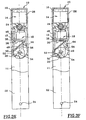
- FIGS. 3A to 3G the references of identical elements being shown in the various figures.
- This very small rotation is permitted by a clearance formed between the free end of the strut 46 and the recess 58 corresponding whose follower 50 is provided.
- This game allows the user to feel that the maneuver is possible but that a locking system prohibits a greater angular maneuver to open the door. This prevents the user from excessive force, imagining that the stand is stuck by a malfunction. In addition, it surely allows a repositioning of the strut in the recess of the follower.
- the strut locks the mechanical means and more particularly the follower 50. Moreover, it is noted that in this position, the counter-plate is glued against the suction cup in the first position of reminder, the permanent magnet ensuring its full attraction.
- the reset lever 40 integral with the counter-plate 34, is also in its first position so that the spring 49 is tensioned, the restoring force exerted being maximum.
- the strut tends to be maintained in the first unlocking position even in case of shock actuation of the stand or in case of impact on the handle.
- An electrical pulse is sent by the electronic means 16 to the pad 32 to cancel at least a portion of the attraction force of the permanent magnet. This negative effort is added to that of the spring.
- the spring 49 which exerts a continuous traction between the counterplate 34 and the strut 46, causes the detachment of said counter plate of the suction cup.
- the permanent magnet regains its power and emits its magnetic field in a normal way.
- the counterplate, detached from the suction cup is at a gap distance that is too great for the backplate to be recalled, especially since said backplate is still subjected to the return force of the spring.
- the lug 42 of the reset lever is remote from the strut in a stable position, so as to allow the detachment of the backplate and the angular movement of the lever even if the strut is blocked in the first position.
- the system is unstable around the axis of rotation 38 of the reset lever.
- the reset lever is closer to the finger 56 of the follower 50 while the strut is removed, allowing the rotation of the follower.
- the strut is maintained in the second position with impossibility of blocking the rotation of the follower as shown in FIG. 3D.
- FIG. 3F it can be seen that the cam is extended with a curvilinear profile corresponding to the movement of the end of the finger of the follower, this in order to avoid in all cases the passage of the finger behind the cam if the user, by an untimely maneuver, the kickstand exceeded the permitted angular rotation.
- the striker, not shown, of the door is actuated at the opening, this in a known manner.
- the return means of the striker ensure a return to stable position of the follower and the return to the initial position of the stand which is secured to it, as shown in Figure 3G.
- the next position is that of the initial figure 2, thus showing the complete cycle.
- the force stored by the spring is provided by the user when operating the stand, the suction pad only needing to unlock the mechanism by releasing the counterplate.
- the operation of the crutches of the two handles is distinct.
- the square is then made in two parts, one secured to the first follower as shown above and the other secured to a second follower 60, the two nuts 50 and 60 being rotated by a pin 62, as shown in FIG. Figure 4A.
- the first follower 50 shown in broken lines, comprises for this purpose a curvilinear open light 64 which receives the pin 62.
- This light of the first follower is of such a size as to allow an angular displacement of the second follower of a few degrees. before being driven by him, for example 10 °.
- the second follower also comprises two slopes 66, only one of which is used, the second symmetrical being made for purposes of symmetry and reversibility.
- the slope 66 concerned is arranged substantially with the same angular positioning as the recesses 58 of the first follower so as to cooperate with the free end of the strut 46.
- this second follower is free of finger.
- the mechanical means, the electromagnetic means and the means for emitting an electrical pulse on the same side of the door have been presented, but the means for emitting an electric pulse for example can be arranged on the side of the door. from the opposite door to the one that supports the rest of the device. This ease of arrangement allows to distribute the congestion if necessary.
- FIGS. 5A to 5C show an arrangement of the same device applied for example to a lock of a container.
- the corresponding block diagram shows how the device works in this arrangement.
- FIG. 5A certain identical and previously described elements are found and the same references are assigned to these elements for a simplification of the drawings while the equivalent elements carry the same elements. same references increased by 100 and the new elements carry references from 200.
- the follower 150 is modified by the presence of a toothing 210 in the lower part intended to mesh with the teeth of a rack 212.
- This rack is guided in translation by any suitable means which is not part of the present invention and which falls under skills of those skilled in the art depending on the application.
- the follower 150 In standby position, as shown in Figure 1, the follower 150 is oriented with its finger 156 vertical.
- the rack 212 is in place and its teeth cooperate with those carried by the follower 150.
- the strut 146 ensures the rotational locking of the follower so that it is impossible to remove the rack 212.
- An electrical pulse is sent by the electronic means to the suction cup 132 to cancel at least a portion of the attraction force of the permanent magnet. This negative effort is added to that of spring 149.
- the spring 149 which exerts a continuous traction between the counterplate 134 and the strut 146, causes the detachment of said counter plate of the suction cup.
- the permanent magnet regains its power and emits its magnetic field in a normal way.
- the counterplate, detached from the suction cup is at a gap distance that is too great for the backplate to be recalled, especially since said backplate is still subjected to the return force of the spring.
- This rack can be secured to a strap or other link while the electric unlocking control device according to the invention is secured to another strap or other link.
- the two parts may be integral with a flap of a container on the one hand and the container itself on the other.
Landscapes
- Lock And Its Accessories (AREA)
Claims (13)
- Vorrichtung zur Steuerung der Drehbewegung einer drehenden Welle eines Schlosses mit elektromagnetischen Mitteln, die zum Empfang eines elektrischen Impulses vorgesehen sind, der durch Mittel (14, 16) infolge der Erfassung von Identifikationszeichen ausgesendet werden kann, und die auf mechanische Mittel einwirken, dadurch gekennzeichnet, dass die elektromagnetischen Mittel in Form eines stromgesteuerten Anziehungselements vorliegen und dass die mechanischen Mittel unter der Wirkung der elektromagnetischen Mittel zwei Positionen einnehmen können, eine erste, so genannte verriegelte Position, in der sie die drehende Welle gegen Drehen festlegen, und eine zweite, so genannte entriegelte Position, in der sie die Drehbewegung der drehenden Welle gestatten, und eine magnetische Gegenplatte (34) umfassen, die zum Zusammenwirken mit dem Anziehungselement zwischen zwei Positionen vorgesehen ist, eine am Anziehungselement haftende Position, wenn sie sich in seinem Magnetfeld befindet, und eine vom Anziehungselement entfernte Position, wenn sie sich außerhalb des Magnetfelds befindet.
- Vorrichtung nach Anspruch 1, dadurch gekennzeichnet, dass das stromgesteuerte Anziehungselement einen Dauermagneten und eine Schaltung zur Erzeugung eines Magnetfelds umfasst, das mindestens einen Teil des Magnetfelds des Dauermagneten bei Empfang des elektrischen Impulses aufhebt.
- Vorrichtung nach Anspruch 1 oder 2, dadurch gekennzeichnet, dass die mechanischen Mittel Rückstellmittel umfassen, die die Gegenplatte wieder in das Magnetfeld einführen können.
- Vorrichtung nach Anspruch 3, dadurch gekennzeichnet, dass die Rückstellmittel in Form eines fest mit der Gegenplatte (34) verbundenen Hebels vorliegen und dass die mechanischen Mittel eine Stütze (46) umfassen, die zwischen einer ersten Position, die der verriegelten Position der drehenden Welle entspricht, und einer zweiten Position, die der entriegelten Position der drehenden Welle entspricht, beweglich ist.
- Vorrichtung nach Anspruch 4, dadurch gekennzeichnet, dass der Rückstellhebel (36) eine damit einstückig gefertigte ebene Fläche umfasst, die die Gegenplatte bildet.
- Vorrichtung nach Anspruch 4 oder 5, dadurch gekennzeichnet, dass der Rückstellhebel (36) einen Ansatz (42) umfasst, der von der Stütze (46) freigegeben ist, wenn sich die Gegenplatte (34) in der ersten Position befindet, und an der Stütze (46) anliegt, wenn sich die Gegenplatte (34) in der zweiten Position befindet.
- Vorrichtung nach einem der Ansprüche 4 bis 6, dadurch gekennzeichnet, dass die mechanischen Mittel (20) eine Nuss (50) mit einem Finger (56) umfassen und dass der Rückstellhebel (36) eine Nocke (44) umfasst, die zur Aufnahme des Fingers und Gewährleistung des Anhebens des Hebels ausgeführt ist.
- Vorrichtung nach Anspruch 7, dadurch gekennzeichnet, dass die Nuss (50) mindestens einen Absatz (58) mit einem Gegenprofil zu dem des freien Endes der Stütze (46) umfasst, um in der Verriegelungsposition unter Bildung eines freien Betätigungsspiels geringer Amplitude zusammenzuwirken.
- Vorrichtung nach Anspruch 7 oder 8, dadurch gekennzeichnet, dass die Nuss (50) mindestens über einen Teil ihres Umfangs eine Verzahnung (210) aufweist, die zum Zusammenwirken mit einer entfernbaren und translatorisch bewegbaren Zahnstange (212) vorgesehen ist.
- Vorrichtung nach einem der Ansprüche 4 bis 10, dadurch gekennzeichnet, dass die mechanischen Mittel (20) elastische Rückholmittel (49) umfassen, die zwischen der Stütze (46) und dem Rückstellhebel (36) angeordnet sind.
- Vorrichtung nach einem der Ansprüche 1 bis 10, dadurch gekennzeichnet, dass sie eine Kassette (12) umfasst, die die mechanischen Verriegelungs-/Entriegelungsmittel und das stromgesteuerte Anziehungselement (32) der elektromagnetischen Entriegelungsmittel (18) stützen.
- Türgriff mit einer elektrischen Steuerungsvorrichtung nach einem der vorhergehenden Ansprüche, dadurch gekennzeichnet, dass er eine zweite Nuss (60) umfasst, die mit einem Antriebszapfen (62) für die erste Nuss versehen ist, die wiederum mit einer Öffnung (64) zur Aufnahme des Zapfens versehen ist, wobei diese zweite Nuss (60) fest mit dem inneren Drücker verbunden ist und mindestens eine Neigung (66) aufweist, die zum Führen der Stütze aus der ersten verriegelten Position in die zweite entriegelte Position vorgesehen ist.
- Türgriff nach Anspruch 12, dadurch gekennzeichnet, dass die Öffnung (64) der zweiten Nuss solche Abmessungen aufweist, dass die erste Nuss (50) mitgeführt wird, wenn die Stütze (46) aus der ersten Nuss (50) ausgerückt wird.
Applications Claiming Priority (3)
| Application Number | Priority Date | Filing Date | Title |
|---|---|---|---|
| FR9716541A FR2772817B1 (fr) | 1997-12-19 | 1997-12-19 | Dispositif electrique de commande de deverouillage d'un arbre tournant, notamment d'une serrure et serrure equipee de ce dispositif |
| FR9716541 | 1997-12-19 | ||
| PCT/FR1998/002742 WO1999032744A1 (fr) | 1997-12-19 | 1998-12-15 | Dispositif electrique de commande de deverrouillage d'un arbre tournant, notamment d'une serrure et serrure equipee de ce dispositif |
Publications (2)
| Publication Number | Publication Date |
|---|---|
| EP1040243A1 EP1040243A1 (de) | 2000-10-04 |
| EP1040243B1 true EP1040243B1 (de) | 2005-09-21 |
Family
ID=9515162
Family Applications (1)
| Application Number | Title | Priority Date | Filing Date |
|---|---|---|---|
| EP98962472A Expired - Lifetime EP1040243B1 (de) | 1997-12-19 | 1998-12-15 | Elektrische steuerungsvorrichtung zur entriegelung einer drehenden welle, insbesondere eines schlosses und schloss mit solcher vorrichtung |
Country Status (6)
| Country | Link |
|---|---|
| EP (1) | EP1040243B1 (de) |
| AU (1) | AU1763899A (de) |
| DE (1) | DE69831688T2 (de) |
| ES (1) | ES2251117T3 (de) |
| FR (1) | FR2772817B1 (de) |
| WO (1) | WO1999032744A1 (de) |
Families Citing this family (4)
| Publication number | Priority date | Publication date | Assignee | Title |
|---|---|---|---|---|
| ES2193793B2 (es) * | 2000-03-01 | 2005-02-01 | Escudos Kala Internacional, S.L. | Mecanismo de condena para cerraduras electronicas. |
| DE102011008213C5 (de) * | 2011-01-10 | 2019-08-22 | Assa Abloy Sicherheitstechnik Gmbh | Türschlossvorrichtung und Verfahren zum Öffnen einer Türschlossvorrichtung |
| EP3130731A1 (de) | 2015-08-10 | 2017-02-15 | Dubois Industries | Schloss für eine tür mit zugangskontrolle |
| FR3087468B1 (fr) | 2018-10-17 | 2022-01-21 | Pascal Moukarzel | Procede de charge d’un dispositif de controle d’acces autonome et appareil de charge temporaire pour sa mise en oeuvre |
Family Cites Families (8)
| Publication number | Priority date | Publication date | Assignee | Title |
|---|---|---|---|---|
| DE1048186B (de) * | 1955-02-15 | 1958-12-31 | Jakob Scheufgen | Vorrichtung zum OEffnen und Schliessen eines Schlosses |
| FR2556034B1 (fr) * | 1983-12-05 | 1987-11-20 | Ferco Int Usine Ferrures | Cremone-serrure a plusieurs points de verrouillage |
| JPS60129378A (ja) * | 1983-12-19 | 1985-07-10 | 美和ロツク工業株式会社 | 電気錠 |
| ATE49448T1 (de) | 1987-02-23 | 1990-01-15 | Fuss Fritz Gmbh & Co | Elektrischer tueroeffner. |
| AT394609B (de) * | 1989-01-03 | 1992-05-25 | Roto Frank Eisenwaren | Getriebe fuer drehkipptueren |
| GB2230550B (en) | 1989-03-18 | 1993-02-10 | Walter Wilson Hugh Clarke | Electromagnetic door lock |
| DE9318001U1 (de) * | 1993-11-24 | 1995-03-30 | Geco GmbH Sicherungstechnik, 25462 Rellingen | Schloß |
| US5678870A (en) * | 1996-01-31 | 1997-10-21 | Sargent Manufacturing Company | Reversible mortise lock |
-
1997
- 1997-12-19 FR FR9716541A patent/FR2772817B1/fr not_active Expired - Fee Related
-
1998
- 1998-12-15 WO PCT/FR1998/002742 patent/WO1999032744A1/fr not_active Ceased
- 1998-12-15 AU AU17638/99A patent/AU1763899A/en not_active Abandoned
- 1998-12-15 DE DE69831688T patent/DE69831688T2/de not_active Expired - Fee Related
- 1998-12-15 ES ES98962472T patent/ES2251117T3/es not_active Expired - Lifetime
- 1998-12-15 EP EP98962472A patent/EP1040243B1/de not_active Expired - Lifetime
Also Published As
| Publication number | Publication date |
|---|---|
| EP1040243A1 (de) | 2000-10-04 |
| AU1763899A (en) | 1999-07-12 |
| DE69831688D1 (de) | 2005-10-27 |
| DE69831688T2 (de) | 2006-06-22 |
| ES2251117T3 (es) | 2006-04-16 |
| FR2772817B1 (fr) | 2000-02-25 |
| FR2772817A1 (fr) | 1999-06-25 |
| WO1999032744A1 (fr) | 1999-07-01 |
Similar Documents
| Publication | Publication Date | Title |
|---|---|---|
| FR2619150A1 (fr) | Serrrure de porte | |
| FR2829170A1 (fr) | Dispositif de securite pour une chambre interne accessible en particulier d'un appareil de cuisson | |
| FR2652375A1 (fr) | Serrure de securite. | |
| FR2766861A1 (fr) | Serrure de porte de vehicule automobile a condamnation electrique | |
| FR2658856A1 (fr) | Dispositif de retardement d'ouverture de porte. | |
| EP1040243B1 (de) | Elektrische steuerungsvorrichtung zur entriegelung einer drehenden welle, insbesondere eines schlosses und schloss mit solcher vorrichtung | |
| FR3033237A3 (fr) | Unite de detection pour boites aux lettres | |
| EP1030011B1 (de) | Kupplungsvorrichtung für einen Schlossaussengriff und seinen beweglichen Schlossriegel | |
| FR2721912A1 (fr) | Dispositif de verrouillage du couvercle d'un bac destine a etre vide par basculement | |
| EP0033261A1 (de) | Kombinations-Sicherheitsschlösser | |
| EP0811738A1 (de) | Verriegelungsvorrichtung | |
| EP2526244A1 (de) | Fahrzeugaussenhülle und vorrichtung zum verschliessen der tür in geschlossener stellung | |
| EP2868842A1 (de) | Verriegelungsvorrichtung einer Schwimmbadabdeckung in entfaltetem Zustand | |
| FR2778940A1 (fr) | Serrure de porte de vehicule automobile a decondamnation electrique et ouverture electrique | |
| EP3844358B1 (de) | Verriegelungsmechanismus eines öffnungselements auf einem rahmen | |
| EP1030008B1 (de) | Schutzvorrichtung für Türzylinderschloss | |
| FR3025235A1 (fr) | Dispositif d'indication, organe d'information pour un tel dispositif et systeme de verrouillage comprenant un tel dispositif | |
| FR2686116A1 (fr) | Serrure comportant un volet mobile de protection. | |
| FR2600369A1 (fr) | Mecanisme d'embrayage notamment pour serrure electronique | |
| FR2885380A1 (fr) | Serrure magnetique pour par exemple, un porte-affiche. | |
| FR2797462A1 (fr) | Serrure mecanique securisee par un actionneur electromecanique pilote par un controle d'acces electrique | |
| FR2796751A1 (fr) | Debrayeur electromagnetique | |
| FR2936543A1 (fr) | Dispositif de protection d'une serrure | |
| FR2879341A1 (fr) | Dispositif de commande a double effet anti-panique et dispositif de verrouillage electromagnetique mettant en oeuvre un tel dispositif | |
| EP2250332A1 (de) | Gesichertes lagergehäuse mit eingebautem alarm |
Legal Events
| Date | Code | Title | Description |
|---|---|---|---|
| PUAI | Public reference made under article 153(3) epc to a published international application that has entered the european phase |
Free format text: ORIGINAL CODE: 0009012 |
|
| 17P | Request for examination filed |
Effective date: 20000627 |
|
| AK | Designated contracting states |
Kind code of ref document: A1 Designated state(s): DE ES FR GB |
|
| 17Q | First examination report despatched |
Effective date: 20010629 |
|
| GRAP | Despatch of communication of intention to grant a patent |
Free format text: ORIGINAL CODE: EPIDOSNIGR1 |
|
| GRAS | Grant fee paid |
Free format text: ORIGINAL CODE: EPIDOSNIGR3 |
|
| GRAA | (expected) grant |
Free format text: ORIGINAL CODE: 0009210 |
|
| AK | Designated contracting states |
Kind code of ref document: B1 Designated state(s): DE ES FR GB |
|
| REG | Reference to a national code |
Ref country code: GB Ref legal event code: FG4D Free format text: NOT ENGLISH |
|
| REF | Corresponds to: |
Ref document number: 69831688 Country of ref document: DE Date of ref document: 20051027 Kind code of ref document: P |
|
| GBT | Gb: translation of ep patent filed (gb section 77(6)(a)/1977) |
Effective date: 20051221 |
|
| REG | Reference to a national code |
Ref country code: ES Ref legal event code: FG2A Ref document number: 2251117 Country of ref document: ES Kind code of ref document: T3 |
|
| PLBE | No opposition filed within time limit |
Free format text: ORIGINAL CODE: 0009261 |
|
| STAA | Information on the status of an ep patent application or granted ep patent |
Free format text: STATUS: NO OPPOSITION FILED WITHIN TIME LIMIT |
|
| 26N | No opposition filed |
Effective date: 20060622 |
|
| PGFP | Annual fee paid to national office [announced via postgrant information from national office to epo] |
Ref country code: ES Payment date: 20081112 Year of fee payment: 11 |
|
| PGFP | Annual fee paid to national office [announced via postgrant information from national office to epo] |
Ref country code: DE Payment date: 20090225 Year of fee payment: 11 |
|
| PGFP | Annual fee paid to national office [announced via postgrant information from national office to epo] |
Ref country code: GB Payment date: 20081110 Year of fee payment: 11 |
|
| GBPC | Gb: european patent ceased through non-payment of renewal fee |
Effective date: 20091215 |
|
| PG25 | Lapsed in a contracting state [announced via postgrant information from national office to epo] |
Ref country code: DE Free format text: LAPSE BECAUSE OF NON-PAYMENT OF DUE FEES Effective date: 20100701 |
|
| PG25 | Lapsed in a contracting state [announced via postgrant information from national office to epo] |
Ref country code: GB Free format text: LAPSE BECAUSE OF NON-PAYMENT OF DUE FEES Effective date: 20091215 |
|
| REG | Reference to a national code |
Ref country code: ES Ref legal event code: FD2A Effective date: 20110404 |
|
| PG25 | Lapsed in a contracting state [announced via postgrant information from national office to epo] |
Ref country code: ES Free format text: LAPSE BECAUSE OF NON-PAYMENT OF DUE FEES Effective date: 20110322 |
|
| PG25 | Lapsed in a contracting state [announced via postgrant information from national office to epo] |
Ref country code: ES Free format text: LAPSE BECAUSE OF NON-PAYMENT OF DUE FEES Effective date: 20091216 |
|
| REG | Reference to a national code |
Ref country code: FR Ref legal event code: PLFP Year of fee payment: 18 |
|
| REG | Reference to a national code |
Ref country code: FR Ref legal event code: PLFP Year of fee payment: 19 |
|
| REG | Reference to a national code |
Ref country code: FR Ref legal event code: PLFP Year of fee payment: 20 |
|
| PGFP | Annual fee paid to national office [announced via postgrant information from national office to epo] |
Ref country code: FR Payment date: 20171220 Year of fee payment: 20 |