EP1040771A2 - Schirm - Google Patents
Schirm Download PDFInfo
- Publication number
- EP1040771A2 EP1040771A2 EP00106814A EP00106814A EP1040771A2 EP 1040771 A2 EP1040771 A2 EP 1040771A2 EP 00106814 A EP00106814 A EP 00106814A EP 00106814 A EP00106814 A EP 00106814A EP 1040771 A2 EP1040771 A2 EP 1040771A2
- Authority
- EP
- European Patent Office
- Prior art keywords
- section
- umbrella
- tilting device
- stroke
- umbrella according
- Prior art date
- Legal status (The legal status is an assumption and is not a legal conclusion. Google has not performed a legal analysis and makes no representation as to the accuracy of the status listed.)
- Withdrawn
Links
- 230000033001 locomotion Effects 0.000 claims abstract description 17
- 239000004744 fabric Substances 0.000 claims description 13
- 230000003068 static effect Effects 0.000 claims description 2
- 238000005452 bending Methods 0.000 abstract description 4
- 241000237858 Gastropoda Species 0.000 description 4
- 238000010276 construction Methods 0.000 description 3
- 238000011161 development Methods 0.000 description 3
- 230000018109 developmental process Effects 0.000 description 3
- 229910001369 Brass Inorganic materials 0.000 description 2
- 239000010951 brass Substances 0.000 description 2
- 239000002023 wood Substances 0.000 description 2
- 230000005540 biological transmission Effects 0.000 description 1
- 230000001419 dependent effect Effects 0.000 description 1
- 230000005484 gravity Effects 0.000 description 1
- 239000000463 material Substances 0.000 description 1
- 238000000034 method Methods 0.000 description 1
- 238000005096 rolling process Methods 0.000 description 1
- 239000007787 solid Substances 0.000 description 1
- 230000002269 spontaneous effect Effects 0.000 description 1
- 230000037072 sun protection Effects 0.000 description 1
Images


Classifications
-
- A—HUMAN NECESSITIES
- A45—HAND OR TRAVELLING ARTICLES
- A45B—WALKING STICKS; UMBRELLAS; LADIES' OR LIKE FANS
- A45B17/00—Tiltable umbrellas
-
- A—HUMAN NECESSITIES
- A45—HAND OR TRAVELLING ARTICLES
- A45B—WALKING STICKS; UMBRELLAS; LADIES' OR LIKE FANS
- A45B2200/00—Details not otherwise provided for in A45B
- A45B2200/10—Umbrellas; Sunshades
- A45B2200/1009—Umbrellas; Sunshades combined with other objects
- A45B2200/1027—Umbrellas; Sunshades combined with other objects with means for generating solar energy
Definitions
- the invention relates to an umbrella with a trunk, with a crown on upper end of the trunk, with pivotally connected to the crown and star struts from the crown and with one of the Cloth struts worn covering, with one along the trunk movable stroke and with star struts extending from the stroke to Open the umbrella and fold it up, using the support struts on the one hand in the area of the stroke and on the other hand in the area of the covering are articulated, as well as with a tilting device for tilting an upper one Umbrella section together with the covering relative to a lower one Screen section.
- Such screens are widely known. They are mainly used as Parasols, which are inserted in a floor stand and by means of the Tilting device can be adjusted to the effective position of the shadow to ensure.
- a known tilting device divides the trunk below the stroke by means of an oblique cut through the trunk into a lower one and an upper screen section. Now the top section of the screen turns around its longitudinal axis - made possible by an appropriately trained joint along the trunk axis - rotated, the upper screen section tilts compared to the lower one.
- the cut surfaces of the top and lower trunk section for even force transmission as flat as possible to each other.
- Another known tilting device comprises a tongue and groove arrangement along the trunk axis, being through the tenon and the Groove a horizontal bolt is guided around which the upper one Can rotate the screen section.
- a locking device for the Inclination device provided, for example a clamping screw in Extension of the bolt.
- Another known tilt device is as Ball joint formed with a ball socket in a lower one Trunk section and a ball rolling in it in the upper trunk section.
- the known tiltable umbrellas also have in common that the stroke at Unclamping is performed on the tilting device.
- the Tilting devices are each fixed to a specific one Adjust angle of inclination.
- a disadvantage of these known tilting devices is that with a larger one Inclination of the upper screen section the tilt stability is relatively low. This can have fatal consequences, especially in windy weather. Of further the known inclination devices have the disadvantage that they are sometimes awkward to use or insufficient weather resistance exhibit. If, for example, the locking device in windy weather is operated or loosens, the upper screen section can be a spontaneous Carry out downward slope movement and represent a source of danger - apart from the fact that in such a case the screen will cause considerable damage can take.
- This task is in one with the screen of the type mentioned first aspect solved in that the tilting device above the stroke is arranged and that the support struts are connected to the hub in such a way that they can follow the tilting movement of the fabric.
- the task is carried out in a second in the umbrella of the type mentioned Aspect solved in that the tilting device is a fixed, a worm associated with the first screen section with a thread and an in engaging the thread, assigned to a second screen section and includes convex tooth section formed, and that the second screen section vertical to the course of the teeth of the tooth section hinged to the first screen section about a pivot axis is.
- the advantages of the invention in its first aspect are particularly therein see that - with the same angle of inclination of the covering - due to the high arranged tilting device the center of gravity of the screen relatively close the stem axis. This also gives the umbrella a high level of stability in windy weather.
- the support struts articulated according to the invention in a special way on the hub. If the Covering in a certain direction must be the support struts that not in this vertical tilt plane, a component of motion in Have horizontal direction to follow the covering.
- Tilting device designed in such a way that the tilting direction is chosen arbitrarily all support struts on the hub must be in the manner described be articulated. (To get a slope in all directions, alternatively, turn the trunk around its longitudinal axis in a base plate; in this case the tilt device only has to be in a vertical plane be designed to be pivotable.)
- Another advantage of the invention is that the stroke in any position Covering is arranged below the tilting device.
- the hub is therefore not guided over the tilting device during clamping. That way prevents the stroke from jamming, for example, with the tilting device or another mechanical handicap can occur.
- the inventive construction allows the screen to a certain extent can also be folded in the inclined state because the tilting device Downward movement of the stroke is not in the way when collapsing.
- Another advantage of the screen according to the invention is that the Headroom is relatively large even with inclined covering.
- the hub side Support struts are supported around two mutually perpendicular axes.
- One of the two axes is that of conventional non-inclined umbrellas State known respective horizontal axis about which the respective Support strut is pivoted when the screen is opened and closed; this axis is called the second axis in the following.
- the other, in the following called the first axis is perpendicular to this second axis.
- the first axes run radially from the trunk or from its longitudinal axis (which coincides with the stroke axis).
- the tracking can the support struts in the direction of the inclined covering also by a Ball joint or any other suitable joint can be realized. Examples this is given in the introduction to the description above.
- a special version for the double articulated bearing above Support struts provide that the hinge pieces are U-shaped with a base and two outer legs are formed, which are preferably parallel to each other run.
- the base is directed towards the hub when articulated, the associated first axis being substantially perpendicular to the base and Longitudinal axis runs.
- the associated support strut is between the two Legs articulated to the joint piece and is preferably by the guided both legs in their pivoting movement about the second axis.
- the tilting device is designed such that it inclines the upper screen section allowed in any direction, all must Support struts can follow the respective tilting movement. It offers itself then - in recourse to the previously described embodiment - to all Articulate joints in the same way on the stroke and the support struts to link the same type to the joint pieces.
- the tilting device is on Trunk or arranged at the crown. In the former alternative there is still a piece of the trunk between the tilting device and the crown. In the second alternative, the focus is closest to Trunk arranged.
- the tilting device can be designed in a variety of ways. For this explicitly include the known and known types of Training options for the tilting device, all of which are advantageous can be used.
- Another tilting device is presented below, which corresponds to the second aspect of the invention.
- the advantages of the invention in their second aspect is that of the second screen section associated and convex tooth section formed with its preferably running in a vertical plane in the Thread of the worm engaging rotatably about its longitudinal axis, which is assigned to the first screen section.
- the convex tooth section runs off in the worm thread and causes - with an appropriate axis connection between the two shield sections - due to its convexity, an inclination of the upper screen section.
- An advantage of the invention according to its second aspect is in particular that an easy to drive, but self-locking under external force Gear is provided.
- the upper part of the screen inclined, so the rotational movement of the screw in a pivoting movement of the upper screen section implemented.
- Intervenes Gust of wind under the covering and wants the upper section of the umbrella can pivot this pivoting movement - with appropriate storage and appropriate choice of material for the worm and the tooth section - However, they cannot be translated into a rotational movement of the screw.
- the combination of worm and tooth section therefore acts in this direction as a self-locking gear; the stability of the screen remains guaranteed. Accordingly, no additional locking device is necessary.
- the tilting device just described is also according to the invention at Umbrellas can be used, in which the tilting device when open Umbrella is arranged below the stroke.
- the general The principle of pivoting of these two constructions is dependent on the position independent of the tilting device.
- the screw is advantageously on the lower screen section provided and thus - except for their rotatability about the then preferably horizontal axis - stationary.
- the tooth section is in this Embodiment assigned to the upper screen section.
- the worm is assigned to the upper screen section and is also pivoted when the screw is turned.
- the worm is preferably operated using a cable pull system and / or a screw handle, which advantageously extends the longitudinal axis the screw is provided, driven. For easier handling and Accessibility can also be on both ends of the snail Screw handle can be arranged.
- the tilting device for preventing an unwanted further inclination of the upper screen section - without prejudice to the advantages of their Not necessary - can be expanded by a fixing device.
- the Fixing device consists for example of ropes with which the upper one inclined screen section with the lower non-inclined screen section is lashable.
- a locking lever known per se or a locking screw is provided in the area of the tilting device, preferably in the extension of the axle bearing of the swivel axis.
- the tilting device is advantageously mechanical or electrical, in particular operated by batteries and / or solar energy.
- a mechanical embodiment can expediently the above Snail via a cable system and / or a screw handle - like for example a handy wing screw - rotated around its longitudinal axis become.
- FIG. 2 show a screen 1 with a straight stem 4 in a floor stand 26 with cloth struts 6 and Support struts 9.
- the screen 1 has a top covering 7 on, which is supported by the cloth struts 6, which in turn by the Support struts 9 are supported.
- the cloth struts 6 are star-shaped around one at the top of the trunk 4 arranged crown 5 arranged (see in particular Fig. 3) and so on the Crown 5 articulated by means of U-shaped joint pieces 25 that they - in the not inclined screen position of Fig. 1 - are pivotable in the vertical direction.
- the covering 7 can be used as in conventional umbrellas open and fold back.
- a cable system to hold the stroke 8 with the umbrella 1 open 28 provided according to the pulley principle (in the other figures, the Pulley no longer shown, but can also be provided there his).
- the one ends are the Support struts 9 supported in a star shape on the hub 8; the other ends of the Support struts 9 are hinged to the cloth struts 6 approximately in the center and around the Pivot axes 24 can be pivoted in a conventional manner (see FIGS. 1 and 2).
- a tilting device 10 which allows a screen section 3 above the tilting device 10 not relative to one moved lower screen section 2 to the covering 7th for example to be able to tilt towards the sun. So that the support struts 9 due their articulation on the one hand on the non-inclined stroke 8 and on the other the cloth struts 6 inclined with the covering 7 are not up to possibly Are loaded, they are mounted on the hub 8 in such a way that they can follow the movement of the fabric 7.
- 3 and 4 is such a mounting of the support struts 9 on the hub 8th shown.
- a joint piece 32 is provided, which in the illustrated Embodiment are U-shaped, i.e. a base 33 and two parallel legs perpendicular to the base 33 and spaced from each other 34 have.
- the base 33 is directed to the hub 8 and at this by one radially to the longitudinal axis 8a of the first axis 30 rotatably mounted (for example by means of a screw and Washers).
- Each support strut 9 is in turn on the stroke side between the two Legs 34 of the associated joint piece 32 about a second axis 31 stored (for example using a brass pin and a self-locking Nut), which runs perpendicular to the first axis 30.
- the legs 34 at the same time assume a management function for the support struts 9 in their Swiveling movement about their respective second axis 31.
- the two Leg 34 - with non-inclined covering 7 - aligned vertically is the second axis 32 in turn aligned horizontally and corresponds to that of conventional umbrellas known hub-side pivot axis for Support struts 9.
- Figs. 1 to 3 is inclined Covering 7 the angle between the individual fabric struts 6 and Trunk section arranged above the tilting device 10 different from the case of the non-inclined covering 7.
- the reason lies in the fixed lengths of the support struts 9 and their articulations on the one hand on the hub 8 and on the other hand on the cloth struts 6.
- the said Angle for the fabric struts 6, which are lower than the inclined position is larger than in the non-inclined state of the covering 7; at the higher lying fabric struts 6, the case is the other way round.
- the tilting device 10 is designed in principle independent of it Location with respect to the stroke 8.
- the invention for both conventional arrangement below the stroke 8 (with the screen 1 folded out), as well as for their arrangement above the stroke 8 - as in FIGS. 1 to 4 shown - is suitable.
- the tilting device 10 according to FIGS. 5 and 6 is a snail 11 in one at the upper end of the lower screen section 2 horizontal bearing 21 is provided, by means of which the screw 11 around their Longitudinal axis 22 is rotatable.
- the screw 11 is in a recess 20 a lower sleeve 15 provided on the upper trunk end of the lower Screen section 2 is placed. Extend on both sides of the screw 11 up two legs 17, which are rounded on the top.
- the ends of a convex extending around a semicircle and in one Vertical toothed section 13 has.
- the upper sleeve 16 has lateral recesses 19 on both sides of the toothed section 13 in such a way that the legs 17 of the lower sleeve 15 the Grip toothed portion 13 of the upper sleeve 16.
- the tooth section 13 engages with a few teeth in the thread 12 of the screw 11.
- the toothed section 13 with the legs 17 is over one horizontally aligned bearing 18 connected so that the upper Screen section 3 relative to the horizontal axis 14 defined by the bearing 18 is pivotable to the lower screen section 2.
- the upper screen section 3 is in its inclined position by the engagement of the toothed section 13 held in the worm thread 12, that is essentially due to the correspondingly high static friction between them Divide.
- the inclination can be set via, for example, a Cable system or a locking screw may be provided. In the latter case acts the locking screw preferably on the legs 17 in the area of Camp 18.
- a cable pull system (not shown) can also be used, with the help of which the screw 11 is driven.
- a A friction wheel or a roller group is provided instead of the wing screw 23.
- the tilting device 10 can also be powered - for example from batteries or from solar energy.
- the screen must be largely weatherproof. Therefore preferably multi-glued wood for the trunk 4, for the struts 6, 9 and the hub 8 and the crown 5 used. Especially for the thinner wooden parts wood that is very resistant to bending and torsion is preferred.
- the Articulated connections that are worm 11 and / or the toothed section 13 advantageously made of solid, weatherproof brass and contribute to the weather resistance of the screen 1 according to the invention.
Landscapes
- Photovoltaic Devices (AREA)
- Walking Sticks, Umbrellas, And Fans (AREA)
Abstract
Description
- Fig. 1
- eine schematische Gesamtansicht eines aufgespannten erfindungsgemäßen Schirmes in ungeneigter Stellung (ohne Bespannung);
- Fig. 2
- der Schirm der Fig. 1 (mit Bespannung ) mit geneigtem oberen Schirmabschnitt;
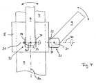
- Fig. 3
- eine perspektivische Detailansicht der Fig. 2 mit Hub, Neigevorrichtung und oberem Schirmabschnitt;
- Fig. 4
- eine schematische Seitenansicht des Hubs und zweier an ihn angelenkten Stützstreben;
- Fig. 5
- eine Seitenansicht der Neigevorrichtung mit Schnecke und in diese eingreifendem Zahnungsabschnitt (teilweise im Schnitt); und
- Fig. 6
- eine gegenüber der Fig. 5 um 90° gedrehte Seitenansicht der Neigevorrichtung (teilweise im Schnitt).
Claims (13)
- Schirm mit einem Stamm (4), mit einer Krone (5) am oberen Ende des Stammes (4), mit verschwenkbar mit der Krone (5) verbundenen und sternförmig von der Krone (5) ausgehenden Tuchstreben (6) und mit einer von den Tuchstreben (6) getragenen Bespannung (7), mit einem entlang des Stammes (4) beweglichen Hub (8) und mit sternförmig vom Hub (8) ausgehenden Stützstreben (9) zum Aufspannen und Zusammenklappen des Schirms (1), wobei die Stützstreben (9) einerseits im Bereich des Hubs (8) und andererseits im Bereich der Bespannung (7) angelenkt sind, sowie mit einer Neigevorrichtung (10) zum Neigen eines oberen Schirmabschnitts (3) samt der Bespannung (7) relativ zu einem unteren Schirmabschnitt (2), dadurch gekennzeichnet, daß die Neigevorrichtung (10) oberhalb des Hubs (8) angeordnet ist und daß die Stützstreben (9) derart mit dem Hub (8) verbunden sind, daß sie der Neigebewegung der Bespannung (7) nachfolgen können.
- Schirm nach Anspruch 1, dadurch gekennzeichnet, daß zumindest die Stützstreben (9), die nicht in einer durch die Neigungsbewegung des oberen Schirmabschnitts (3) aufgespannten Vertikalebene schwenkbar sind, hubseitig um zwei zueinander senkrecht stehende Achsen (30, 31) gelagert sind.
- Schirm nach Anspruch 2, dadurch gekennzeichnet, daß Gelenkstücke (32) sternförmig um im wesentlichen radial zur Hublängsachse (8a) verlaufende erste Achsen (30) drehbar an dem Hub (8) angelenkt sind und daß jeweils eine Stützstrebe (9) an einem solchen Gelenkstück (32) um eine zu diesen ersten Achsen (30) jeweils senkrechte zweite Achse (31) schwenkbar angelenkt ist.
- Schirm nach Anspruch 3, dadurch gekennzeichnet, daß die Gelenkstücke (32) U-förmig mit einer Basis (33) und zwei im wesentlichen zur Basis (33) senkrecht verlaufenden beabstandeten Schenkeln (34) ausgebildet sind, wobei die Basis (33) um die jeweilige erste Achse (30) drehbar am Hub (8) und die jeweilige Stützstrebe (9) zwischen den beiden Schenkeln (34) um die zweite Achse (31) schwenkbar angelenkt ist.
- Schirm nach einem der vorhergehenden Ansprüche, dadurch gekennzeichnet, daß die Neigevorrichtung (10) am Stamm (4) oder an der Krone (5) angeordnet ist.
- Schirm nach einem der vorhergehenden Ansprüche, dadurch gekennzeichnet, die Neigevorrichtung (10) derart ausgebildet ist, daß sie eine Neigung des oberen Schirmabschnitts (3) in alle Richtungen erlaubt.
- Schirm nach dem Oberbegriff des Anspruchs 1, insbesondere nach einem der vorhergehenden Ansprüche, dadurch gekennzeichnet, daß die Neigevorrichtung (10) eine einem ersten Schirmabschnitt (2) zugeordnete Schnecke (11) mit einem Gewinde (12) und einen in das Gewinde (12) eingreifenden, einem zweiten Schirmabschnitt (3) zugeordneten und konvex zur Schnecke (11) ausgebildeten Zahnungsabschnitt (13) umfaßt, und daß der zweite Schirmabschnitt (3) vertikal zum Zahnungsverlauf des Zahnungsabschnitts (13) an dem ersten Schirmabschnitt (2) um eine Schwenkachse (14) schwenkbar angelenkt ist.
- Schirm nach Anspruch 7, dadurch gekennzeichnet, daß die Schnecke (11) an dem unteren Schirmabschnitt (2) und der Zahnungsabschnitt (13) an dem oberen Schirmabschnitt (3) angeordnet sind.
- Schirm nach Anspruch 7 oder 8, dadurch gekennzeichnet, daß die Stammabschnitte des ersten und des zweiten Schirmabschnitts (2, 3) an ihren sich zugewandten Enden eine erste bzw. eine zweite Hülse (15, 16) aufweisen, wobei die zweite Hülse (16) den Zahnungsabschnitt (13) und die erste Hülse (15) die Schnecke (11) aufnimmt und die erste Hülse (15) zudem zwei seitliche Schenkel (17) aufweist, welche den Zahnungsabschnitt (13) umgreifen, und daß die Schwenkachse (14) durch die beiden Schenkel (17) und den Zahnungsabschnitt (13) verläuft.
- Schirm nach einem der Ansprüche 7 bis 9, dadurch gekennzeichnet, daß die Schnecke (11) über ein Seilzugsystem und/oder einen Schraubgriff (18) drehbar ist.
- Schirm nach einem der vorhergehenden Ansprüche, dadurch gekennzeichnet, daß die Neigevorrichtung (10) mechanisch oder elektrisch, insbesondere durch Batterien und/oder Solarenergie, betätigbar ist.
- Schirm nach einem der vorhergehenden Ansprüche, dadurch gekennzeichnet, daß die Neigevorrichtung (10) mit einer Festsetzvorrichtung in einer Neigestellung festsetzbar ist.
- Schirm nach einem der vorhergehenden Ansprüche, dadurch gekennzeichnet, daß die Neigevorrichtung (10) durch Haftreibung in einer gewählten Neigestellung bleibt.
Applications Claiming Priority (6)
| Application Number | Priority Date | Filing Date | Title |
|---|---|---|---|
| ZA99790 | 1999-04-02 | ||
| ZA9900790 | 1999-04-02 | ||
| AT2972000 | 2000-03-06 | ||
| AT2972000U | 2000-03-06 | ||
| DE20003918U DE20003918U1 (de) | 2000-03-06 | 2000-03-06 | Schirm |
| DE20003918U | 2000-03-06 |
Publications (2)
| Publication Number | Publication Date |
|---|---|
| EP1040771A2 true EP1040771A2 (de) | 2000-10-04 |
| EP1040771A3 EP1040771A3 (de) | 2001-06-06 |
Family
ID=27146121
Family Applications (1)
| Application Number | Title | Priority Date | Filing Date |
|---|---|---|---|
| EP00106814A Withdrawn EP1040771A3 (de) | 1999-04-02 | 2000-03-30 | Schirm |
Country Status (1)
| Country | Link |
|---|---|
| EP (1) | EP1040771A3 (de) |
Cited By (3)
| Publication number | Priority date | Publication date | Assignee | Title |
|---|---|---|---|---|
| WO2002094053A1 (en) * | 2001-05-22 | 2002-11-28 | Hoyland Fox Limited | Tilting umbrella |
| WO2006109103A1 (en) * | 2005-04-15 | 2006-10-19 | KÉNINGER, Csaba | Tiltable parasol support |
| US9155364B2 (en) | 2013-10-24 | 2015-10-13 | Mario Jason | Sunshade positioning device |
Family Cites Families (7)
| Publication number | Priority date | Publication date | Assignee | Title |
|---|---|---|---|---|
| US2724396A (en) * | 1953-03-10 | 1955-11-22 | Cohen Alfred G | Tilting pole umbrella |
| US3044478A (en) * | 1961-04-25 | 1962-07-17 | California Umbrella Company | Tiltable umbrella |
| US3129715A (en) * | 1961-08-15 | 1964-04-21 | Finkel Outdoor Prod | Motor driven winding mechanism |
| US3182673A (en) * | 1963-07-15 | 1965-05-11 | Cohen Alfred G | Tiltable umbrella having gear rack operating means |
| CA2001809C (en) * | 1988-11-09 | 1994-11-29 | John Michael Earnshaw | Umbrella frame |
| PT8989U (pt) * | 1994-03-11 | 1996-10-31 | Manufacturas Mecanicas Flexus | Dispositivo combinado de articulacao e abertura/fecho para guarda-sol |
| GB9409356D0 (en) * | 1994-05-11 | 1994-06-29 | Hoyland Fox Ltd | Umbrella frame |
-
2000
- 2000-03-30 EP EP00106814A patent/EP1040771A3/de not_active Withdrawn
Non-Patent Citations (1)
| Title |
|---|
| None |
Cited By (4)
| Publication number | Priority date | Publication date | Assignee | Title |
|---|---|---|---|---|
| WO2002094053A1 (en) * | 2001-05-22 | 2002-11-28 | Hoyland Fox Limited | Tilting umbrella |
| US7207343B2 (en) | 2001-05-22 | 2007-04-24 | Hoyland Fox Limited | Tilting umbrella with actuator having operating location on lower shaft to tilt upper shaft |
| WO2006109103A1 (en) * | 2005-04-15 | 2006-10-19 | KÉNINGER, Csaba | Tiltable parasol support |
| US9155364B2 (en) | 2013-10-24 | 2015-10-13 | Mario Jason | Sunshade positioning device |
Also Published As
| Publication number | Publication date |
|---|---|
| EP1040771A3 (de) | 2001-06-06 |
Similar Documents
| Publication | Publication Date | Title |
|---|---|---|
| DE60305663T2 (de) | Kippschirm | |
| DE102007021821B4 (de) | Schirm | |
| DE102007021400B4 (de) | Schirm | |
| EP0052258A2 (de) | Sonnenschirm | |
| DE2732654B2 (de) | Gelenkbeschlag für Leiterteile | |
| EP2842446A1 (de) | Schwenkbarer Sonnenschirm | |
| EP1097652A1 (de) | Freiarmschirm | |
| DE202004004350U1 (de) | Transportabler großer Schirm | |
| DE3031318C2 (de) | Dachflächenfenster | |
| EP2255693A1 (de) | Verriegelungsmechanismus | |
| EP0824054A1 (de) | Spanntisch | |
| DE69719904T2 (de) | Vorrichtung zur Halterung von Sonnenschirmen | |
| EP1040771A2 (de) | Schirm | |
| DE4113828C2 (de) | Fahrzeug zum Mähen | |
| EP1550383A1 (de) | Schirm, insbesondere Grossschirm | |
| DE29712024U1 (de) | Schirmaufbau mit einem seitlich angeordneten Stiel und einem drehbar um diesen Stiel angeordneten Schirmdach | |
| DE20003918U1 (de) | Schirm | |
| DE69015553T2 (de) | Verfahren und Vorrichtung für das Heben und Entfernen von einer normalerweise horizontalen Plattform. | |
| DE102004043192B4 (de) | Tisch | |
| DE3416889A1 (de) | Vorrichtung zum ausbreiten und einziehen einer schutzplane | |
| DE19700540C2 (de) | Möbelstück mit einer Plattenanordnung | |
| DE69907086T2 (de) | Zusammenklappbarer Fahrradständer | |
| EP1467640B1 (de) | Standschirm | |
| EP0802748A1 (de) | Vorrichtung zur verstellung der höhe und/oder neigung der tischplatte eines tisches | |
| DE9110675U1 (de) | Standschirm mit einziehbaren Dachstangen |
Legal Events
| Date | Code | Title | Description |
|---|---|---|---|
| PUAI | Public reference made under article 153(3) epc to a published international application that has entered the european phase |
Free format text: ORIGINAL CODE: 0009012 |
|
| AK | Designated contracting states |
Kind code of ref document: A2 Designated state(s): AT BE CH CY DE DK ES FI FR GB GR IE IT LI LU MC NL PT SE |
|
| AX | Request for extension of the european patent |
Free format text: AL;LT;LV;MK;RO;SI |
|
| PUAL | Search report despatched |
Free format text: ORIGINAL CODE: 0009013 |
|
| AK | Designated contracting states |
Kind code of ref document: A3 Designated state(s): AT BE CH CY DE DK ES FI FR GB GR IE IT LI LU MC NL PT SE |
|
| AX | Request for extension of the european patent |
Free format text: AL;LT;LV;MK;RO;SI |
|
| AKX | Designation fees paid | ||
| REG | Reference to a national code |
Ref country code: DE Ref legal event code: 8566 |
|
| STAA | Information on the status of an ep patent application or granted ep patent |
Free format text: STATUS: THE APPLICATION IS DEEMED TO BE WITHDRAWN |
|
| 18D | Application deemed to be withdrawn |
Effective date: 20011207 |