EP1040899A2 - Schneidpresse - Google Patents
Schneidpresse Download PDFInfo
- Publication number
- EP1040899A2 EP1040899A2 EP00104328A EP00104328A EP1040899A2 EP 1040899 A2 EP1040899 A2 EP 1040899A2 EP 00104328 A EP00104328 A EP 00104328A EP 00104328 A EP00104328 A EP 00104328A EP 1040899 A2 EP1040899 A2 EP 1040899A2
- Authority
- EP
- European Patent Office
- Prior art keywords
- cutting
- belt
- press
- cutting press
- tape
- Prior art date
- Legal status (The legal status is an assumption and is not a legal conclusion. Google has not performed a legal analysis and makes no representation as to the accuracy of the status listed.)
- Granted
Links
- 238000001816 cooling Methods 0.000 claims description 12
- 229910000831 Steel Inorganic materials 0.000 claims description 5
- 239000010959 steel Substances 0.000 claims description 5
- 239000011888 foil Substances 0.000 abstract description 4
- 239000000463 material Substances 0.000 description 5
- 239000000853 adhesive Substances 0.000 description 2
- 230000001070 adhesive effect Effects 0.000 description 2
- 238000004026 adhesive bonding Methods 0.000 description 1
- 239000010426 asphalt Substances 0.000 description 1
- 230000015572 biosynthetic process Effects 0.000 description 1
- 230000005494 condensation Effects 0.000 description 1
- 238000009833 condensation Methods 0.000 description 1
- 238000010276 construction Methods 0.000 description 1
- 239000002826 coolant Substances 0.000 description 1
- 238000006073 displacement reaction Methods 0.000 description 1
- 230000000694 effects Effects 0.000 description 1
- 239000012535 impurity Substances 0.000 description 1
- 239000007788 liquid Substances 0.000 description 1
- 239000003973 paint Substances 0.000 description 1
- 238000010422 painting Methods 0.000 description 1
- 238000004080 punching Methods 0.000 description 1
- 239000007921 spray Substances 0.000 description 1
Images
Classifications
-
- B—PERFORMING OPERATIONS; TRANSPORTING
- B26—HAND CUTTING TOOLS; CUTTING; SEVERING
- B26D—CUTTING; DETAILS COMMON TO MACHINES FOR PERFORATING, PUNCHING, CUTTING-OUT, STAMPING-OUT OR SEVERING
- B26D7/00—Details of apparatus for cutting, cutting-out, stamping-out, punching, perforating, or severing by means other than cutting
- B26D7/20—Cutting beds
-
- B—PERFORMING OPERATIONS; TRANSPORTING
- B26—HAND CUTTING TOOLS; CUTTING; SEVERING
- B26F—PERFORATING; PUNCHING; CUTTING-OUT; STAMPING-OUT; SEVERING BY MEANS OTHER THAN CUTTING
- B26F1/00—Perforating; Punching; Cutting-out; Stamping-out; Apparatus therefor
- B26F1/38—Cutting-out; Stamping-out
- B26F1/40—Cutting-out; Stamping-out using a press, e.g. of the ram type
Definitions
- the invention relates to a for cutting workpieces cutting press formed from a film, which a press table with a ribbon running over it has that by two on each side of the press table arranged deflection rollers is guided all around and on which the film for making the cutouts by means of a cutting tool rests in the area of the press table.
- Cutting presses of the above type are, for example used to cut soundproofing parts from bitumen foils, which on body parts of motor vehicles be glued. Usually have such cutting presses several cutting tools side by side.
- the tape serves to transport the film under the cutting tools and for subsequent transportation. It usually consists of Rubber or a rubber-like plastic.
- To cut out of the soundproofing parts cuts the respective cutting tool each during a short-term standstill of the tape through the film lying on the tape except for the tape. It cannot be avoided that with each cut, the one that supports the film Tape is at least slightly damaged. Similar to formerly formed by vehicles with spikes on road surfaces this leaves traces in the circulating band that are relative quickly lead so deep into the tape that it renews must become.
- the invention is based on the problem of a To design a cutting press of the type mentioned at the beginning that your circulating clocked tape is as large as possible Has durability.
- the belt can be used on the deflection rollers in very different ways shifted relative to the cutting tools become. There is particularly little construction effort Creation of the ability to move required if according to an advantageous development of the invention Means for moving the belt by means of a height adjustment a bearing of a deflecting roller are formed. With such a bearing height adjustment, that the belt moves by itself as it rotates shifted to one side.
- Bearing height adjustment one that can be moved by a spindle Wedge, on which a bearing of the deflecting roller is supported is.
- the band is made of steel.
- Such one Band has a particularly long durability and leads to that the formation of punch burrs on the workpieces Deformation of the band is avoided.
- Such a Punching burr can cause that when fitting the workpieces Material crumbles that when later painting the parts provided with the material interfere by impurities in the paint layer due to the material form.
- using a steel band is more reliable to achieve that the workpieces during the cutting stroke be completely separated from the cutting grid.
- the tape with belt cooling for cooling to below the dew point the surrounding air.
- Belt cooling is basically with all cutting presses advantageous with a circumferential steel band, where the problem of undesirably strong adhesion of the cutting good exists.
- the belt cooling could, for example, by a cooler can be realized via the below the press table returning run of the tape is performed. Especially the belt cooling is easy to implement, if according to another development of the invention Belt cooling is provided in one of the deflecting rollers.
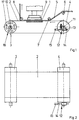
- Figure 1 shows a press table 1, over which a belt 2 made of steel, which is endless two trackless deflection rollers 3, 4 kept under tension is and can be set in a clocked orbital movement.
- a band-shaped film 5 is made above the band 2 bituminous material represented by rollers 6, 7, 8 brought into contact with the band 2 from above becomes.
- a cutting tool 9 moves from above into the film 5 except for the tape 2 and cuts a workpiece from the film 5.
- the deflecting rollers 3, 4 are each supported by bearings 10, 11 stored on each side.
- Bearing height adjustment 12 which is only on the bearing 11 is provided.
- This bearing height adjustment 12 has one Wedge 13 on which the bearing 11 is supported.
- the wedge 13 is by driving a spindle 14 by means of a Actuator 15 more or less in the horizontal direction to adjust. Because of its wedge surface, this will the bearing 11 more or less raised or lowered, which has the consequence that the band 2 from that shown in Figure 2 middle position more or less on the one hand or other side of the deflection rollers 3, 4 runs out, that is there is a transverse displacement of the belt 2.
- a belt cooling 16 which is caused by a cooling medium flowed through tubes 17 is formed.
- This belt cooling 16 is designed to cause condensation from Moisture comes from the air on the tape 2. Thereby the film 5 adheres less strongly to the tape 2.
- FIG. 2 illustrates that the deflection rollers 3, 4 are longer are than the band 2 is wide.
- the tape has 2 the opportunity to look through the effect of the height adjustment 12 sideways to one side or the other to move on the guide rollers 3, 4.
Landscapes
- Life Sciences & Earth Sciences (AREA)
- Forests & Forestry (AREA)
- Engineering & Computer Science (AREA)
- Mechanical Engineering (AREA)
- Perforating, Stamping-Out Or Severing By Means Other Than Cutting (AREA)
- Casting Or Compression Moulding Of Plastics Or The Like (AREA)
- Milling Processes (AREA)
- Magnetic Resonance Imaging Apparatus (AREA)
- Auxiliary Devices For And Details Of Packaging Control (AREA)
- Valve Device For Special Equipments (AREA)
Abstract
Description
- Fig.1
- eine Seitenansicht einer Schneidpresse nach der Erfindung,
- Fig.2
- eine Draufsicht auf einen unteren Bereich der Schneidpresse.
- 1
- Pressentisch
- 2
- Band
- 3
- Umlenkwalze
- 4
- Umlenkwalze
- 5
- Folie
- 6
- Walze
- 7
- Walze
- 8
- Walze
- 9
- Schneidwerkzeug
- 10
- Lager
- 11
- Lager
- 12
- Lagerhöhenverstellung
- 13
- Keil
- 14
- Spindel
- 15
- Stellmotor
- 16
- Bandkühlung
- 17
- Rohr
Claims (6)
- Zum Ausschneiden von Werkstücken aus einer Folie (5) ausgebildete Schneidpresse, welche einen Pressentisch (1) mit einem darüber geführten Band (2) hat, das durch zwei jeweils an einer Seite des Pressentisches (1) angeordnete Umlenkwalzen (3, 4) umlaufend geführt ist und auf das die Folie (5) zum Ausführen der Ausschnitte mittels eines Schneidwerkzeugs (9) im Bereich des Pressentisches (1) aufliegt, dadurch gekennzeichnet, dass die Schneidpresse Mittel zum Verschieben des Bandes (2) quer zu einer Umlaufrichtung aufweist.
- Schneidpresse nach Anspruch 1, dadurch gekennzeichnet, dass die Mittel zum Verschieben des Bandes (2) durch eine Lagerhöhenverstellung (12) eines Lagers (11) einer Umlenkwalze (4) gebildet sind.
- Schneidpresse nach Anspruch 2, dadurch gekennzeichnet, dass die Lagerhöhenverstellung (12) einen von einer Spindel (14) verfahrbaren Keil (13) hat, auf welchem ein Lager (11) der Umlenkwalze (4) abgestützt ist.
- Schneidpresse nach zumindest einem der vorangehenden Ansprüche, dadurch gekennzeichnet, dass das Band (2) aus Stahl besteht.
- Schneidpresse nach zumindest einem der vorangehenden Ansprüche, dadurch gekennzeichnet, dass das Band (2) mit einer Bandkühlung (16) zur Kühlung bis unterhalb des Taupunktes der umgebenden Luft versehen ist.
- Schneidpresse nach Anspruch 5, dadurch gekennzeichnet, dass die Bandkühlung (16) in einer der Umlenkwalzen (3, 4) vorgesehen ist.
Applications Claiming Priority (2)
| Application Number | Priority Date | Filing Date | Title |
|---|---|---|---|
| DE19914431A DE19914431A1 (de) | 1999-03-30 | 1999-03-30 | Schneidpresse |
| DE19914431 | 1999-03-30 |
Publications (3)
| Publication Number | Publication Date |
|---|---|
| EP1040899A2 true EP1040899A2 (de) | 2000-10-04 |
| EP1040899A3 EP1040899A3 (de) | 2003-06-11 |
| EP1040899B1 EP1040899B1 (de) | 2005-09-28 |
Family
ID=7902964
Family Applications (1)
| Application Number | Title | Priority Date | Filing Date |
|---|---|---|---|
| EP00104328A Expired - Lifetime EP1040899B1 (de) | 1999-03-30 | 2000-03-02 | Schneidpresse |
Country Status (5)
| Country | Link |
|---|---|
| EP (1) | EP1040899B1 (de) |
| JP (1) | JP2000288996A (de) |
| AT (1) | ATE305373T1 (de) |
| DE (3) | DE19914431A1 (de) |
| ES (1) | ES2245913T3 (de) |
Families Citing this family (1)
| Publication number | Priority date | Publication date | Assignee | Title |
|---|---|---|---|---|
| CN114851282B (zh) * | 2022-05-24 | 2024-06-07 | 镇江银海科技材料有限公司 | 一种用于花纹铝箔的切割设备及其使用方法 |
Family Cites Families (8)
| Publication number | Priority date | Publication date | Assignee | Title |
|---|---|---|---|---|
| DE1939946U (de) * | 1966-03-08 | 1966-06-02 | A W Schultze Gummi Und Asbest | Kunstoff-stanzunterlage. |
| DE2010834A1 (de) * | 1970-03-07 | 1971-09-23 | Baumann, Wilfried, 4801 Hoberge-Uerentrup | Maschine zum Stanzen von nichtmetallischen Werkstoffen |
| JPS6044120B2 (ja) * | 1979-01-08 | 1985-10-01 | 三菱重工業株式会社 | ロ−タリダイカツタ |
| DE3614106A1 (de) * | 1986-04-25 | 1987-10-29 | Bhs Bayerische Berg | Schneidvorrichtung, insbesondere querschneider fuer wellpappe, vollpappe oder dgl. |
| DE3824322A1 (de) * | 1988-07-18 | 1990-01-25 | Schoen & Cie Gmbh | Vorrichtung zum verschieben einer stanzgegenplatte an einer stanzmaschine |
| DE4223050C2 (de) * | 1992-07-14 | 1995-05-24 | Wilhelm Aichele | Vorrichtung zum Formschneiden vorlaufender Werkstoffbahnen |
| EP0710531B1 (de) * | 1994-11-07 | 2000-04-12 | Eastman Kodak Company | Vorrichtung und Verfahren zum Langsscheiden von Bandmaterial |
| DE29700519U1 (de) * | 1997-01-14 | 1998-05-14 | Gizeh-Werk GmbH, 51702 Bergneustadt | Vorrichtung zum Querschneiden eines strangförmigen Gebildes |
-
1999
- 1999-03-30 DE DE19914431A patent/DE19914431A1/de not_active Withdrawn
-
2000
- 2000-01-14 DE DE20000555U patent/DE20000555U1/de not_active Expired - Lifetime
- 2000-03-02 EP EP00104328A patent/EP1040899B1/de not_active Expired - Lifetime
- 2000-03-02 DE DE50011231T patent/DE50011231D1/de not_active Expired - Lifetime
- 2000-03-02 ES ES00104328T patent/ES2245913T3/es not_active Expired - Lifetime
- 2000-03-02 AT AT00104328T patent/ATE305373T1/de not_active IP Right Cessation
- 2000-03-03 JP JP2000058299A patent/JP2000288996A/ja active Pending
Also Published As
| Publication number | Publication date |
|---|---|
| JP2000288996A (ja) | 2000-10-17 |
| DE19914431A1 (de) | 2000-10-05 |
| ATE305373T1 (de) | 2005-10-15 |
| DE20000555U1 (de) | 2000-04-27 |
| EP1040899A3 (de) | 2003-06-11 |
| DE50011231D1 (de) | 2006-02-09 |
| ES2245913T3 (es) | 2006-02-01 |
| EP1040899B1 (de) | 2005-09-28 |
Similar Documents
| Publication | Publication Date | Title |
|---|---|---|
| AT390044B (de) | Foerdereinrichtung fuer werkstuecke bzw. werkstuecktraeger | |
| EP2560861B1 (de) | Fördereinrichtung für automatisierungsstrassen | |
| DE2419088A1 (de) | Vorrichtung zum abstuetzen und bewegen von foerdereinheiten | |
| EP3283240B1 (de) | Auflagetisch für biegemaschine | |
| DE3246129C2 (de) | Vorrichtung zum genauen Anhalten von Fahrzeugen | |
| DE69003785T2 (de) | Fördervorrichtung. | |
| EP0553764B1 (de) | Einschienenhängebahn | |
| EP1140555B1 (de) | Schiene zur führung von laufschienen von kfz-komponenten und verfahren zu ihrer herstellung | |
| EP3684534A1 (de) | Unterflur-radsatzdrehmaschine mit verstellbarer spurweite | |
| WO2008037622A1 (de) | Werkstückträgereinrichtung sowie friktionsförderer | |
| DE3012355C2 (de) | ||
| CH679563A5 (de) | ||
| EP1040899B1 (de) | Schneidpresse | |
| DE1527383A1 (de) | Vorrichtung zum bewegbaren Abstuetzen von Schweisseinrichtungen | |
| DE68904577T2 (de) | Stellvorrichtung fuer ein eisenbahnfahrzeug auf einer raddrehbank. | |
| DE4022574C2 (de) | ||
| EP0266442B1 (de) | Verlegeeinrichtung | |
| AT501316B1 (de) | Plattenaufteilsäge mit niederhaltevorrichtung | |
| DE102016113548A1 (de) | Furnierschichtholzprodukt und Verfahren zu seiner Herstellung | |
| DE4004487A1 (de) | Vorrichtung zum schweissen von bahnfoermigem material | |
| DE3310635C2 (de) | ||
| EP3759038B1 (de) | Transportaufsatz, zugmittel, plattenförderer und verfahren | |
| DE3448491C2 (de) | Fördereinrichtung, insbesondere für eine Montagemaschine | |
| EP0123065A2 (de) | Sägeanlage zum Abtrennen von Teilstücken aus Profilen | |
| DE2120186C3 (de) | Vorrichtung zum Stanzen von Formlingen oder Materialbahnen |
Legal Events
| Date | Code | Title | Description |
|---|---|---|---|
| PUAI | Public reference made under article 153(3) epc to a published international application that has entered the european phase |
Free format text: ORIGINAL CODE: 0009012 |
|
| AK | Designated contracting states |
Kind code of ref document: A2 Designated state(s): AT BE CH CY DE DK ES FI FR GB GR IE IT LI LU MC NL PT SE |
|
| AX | Request for extension of the european patent |
Free format text: AL;LT;LV;MK;RO;SI |
|
| PUAL | Search report despatched |
Free format text: ORIGINAL CODE: 0009013 |
|
| AK | Designated contracting states |
Designated state(s): AT BE CH CY DE DK ES FI FR GB GR IE IT LI LU MC NL PT SE |
|
| AX | Request for extension of the european patent |
Extension state: AL LT LV MK RO SI |
|
| 17P | Request for examination filed |
Effective date: 20031211 |
|
| AKX | Designation fees paid |
Designated state(s): AT BE CH CY DE DK ES FI FR GB GR IE IT LI LU MC NL PT SE |
|
| 17Q | First examination report despatched |
Effective date: 20040428 |
|
| GRAP | Despatch of communication of intention to grant a patent |
Free format text: ORIGINAL CODE: EPIDOSNIGR1 |
|
| GRAS | Grant fee paid |
Free format text: ORIGINAL CODE: EPIDOSNIGR3 |
|
| GRAA | (expected) grant |
Free format text: ORIGINAL CODE: 0009210 |
|
| RAP1 | Party data changed (applicant data changed or rights of an application transferred) |
Owner name: CWW-GERKO AKUSTIK GMBH |
|
| AK | Designated contracting states |
Kind code of ref document: B1 Designated state(s): AT BE CH CY DE DK ES FI FR GB GR IE IT LI LU MC NL PT SE |
|
| PG25 | Lapsed in a contracting state [announced via postgrant information from national office to epo] |
Ref country code: IT Free format text: LAPSE BECAUSE OF FAILURE TO SUBMIT A TRANSLATION OF THE DESCRIPTION OR TO PAY THE FEE WITHIN THE PRESCRIBED TIME-LIMIT;WARNING: LAPSES OF ITALIAN PATENTS WITH EFFECTIVE DATE BEFORE 2007 MAY HAVE OCCURRED AT ANY TIME BEFORE 2007. THE CORRECT EFFECTIVE DATE MAY BE DIFFERENT FROM THE ONE RECORDED. Effective date: 20050928 Ref country code: FI Free format text: LAPSE BECAUSE OF FAILURE TO SUBMIT A TRANSLATION OF THE DESCRIPTION OR TO PAY THE FEE WITHIN THE PRESCRIBED TIME-LIMIT Effective date: 20050928 Ref country code: IE Free format text: LAPSE BECAUSE OF FAILURE TO SUBMIT A TRANSLATION OF THE DESCRIPTION OR TO PAY THE FEE WITHIN THE PRESCRIBED TIME-LIMIT Effective date: 20050928 Ref country code: NL Free format text: LAPSE BECAUSE OF FAILURE TO SUBMIT A TRANSLATION OF THE DESCRIPTION OR TO PAY THE FEE WITHIN THE PRESCRIBED TIME-LIMIT Effective date: 20050928 |
|
| REG | Reference to a national code |
Ref country code: GB Ref legal event code: FG4D Free format text: NOT ENGLISH |
|
| REG | Reference to a national code |
Ref country code: CH Ref legal event code: EP |
|
| GBT | Gb: translation of ep patent filed (gb section 77(6)(a)/1977) |
Effective date: 20050928 |
|
| REG | Reference to a national code |
Ref country code: IE Ref legal event code: FG4D Free format text: LANGUAGE OF EP DOCUMENT: GERMAN |
|
| PG25 | Lapsed in a contracting state [announced via postgrant information from national office to epo] |
Ref country code: DK Free format text: LAPSE BECAUSE OF FAILURE TO SUBMIT A TRANSLATION OF THE DESCRIPTION OR TO PAY THE FEE WITHIN THE PRESCRIBED TIME-LIMIT Effective date: 20051228 Ref country code: SE Free format text: LAPSE BECAUSE OF FAILURE TO SUBMIT A TRANSLATION OF THE DESCRIPTION OR TO PAY THE FEE WITHIN THE PRESCRIBED TIME-LIMIT Effective date: 20051228 Ref country code: GR Free format text: LAPSE BECAUSE OF FAILURE TO SUBMIT A TRANSLATION OF THE DESCRIPTION OR TO PAY THE FEE WITHIN THE PRESCRIBED TIME-LIMIT Effective date: 20051228 |
|
| REG | Reference to a national code |
Ref country code: ES Ref legal event code: FG2A Ref document number: 2245913 Country of ref document: ES Kind code of ref document: T3 |
|
| REF | Corresponds to: |
Ref document number: 50011231 Country of ref document: DE Date of ref document: 20060209 Kind code of ref document: P |
|
| PGFP | Annual fee paid to national office [announced via postgrant information from national office to epo] |
Ref country code: FR Payment date: 20060214 Year of fee payment: 7 |
|
| PG25 | Lapsed in a contracting state [announced via postgrant information from national office to epo] |
Ref country code: PT Free format text: LAPSE BECAUSE OF FAILURE TO SUBMIT A TRANSLATION OF THE DESCRIPTION OR TO PAY THE FEE WITHIN THE PRESCRIBED TIME-LIMIT Effective date: 20060228 |
|
| NLV1 | Nl: lapsed or annulled due to failure to fulfill the requirements of art. 29p and 29m of the patents act | ||
| PG25 | Lapsed in a contracting state [announced via postgrant information from national office to epo] |
Ref country code: AT Free format text: LAPSE BECAUSE OF NON-PAYMENT OF DUE FEES Effective date: 20060302 |
|
| PG25 | Lapsed in a contracting state [announced via postgrant information from national office to epo] |
Ref country code: LI Free format text: LAPSE BECAUSE OF NON-PAYMENT OF DUE FEES Effective date: 20060331 Ref country code: MC Free format text: LAPSE BECAUSE OF NON-PAYMENT OF DUE FEES Effective date: 20060331 Ref country code: BE Free format text: LAPSE BECAUSE OF NON-PAYMENT OF DUE FEES Effective date: 20060331 Ref country code: CH Free format text: LAPSE BECAUSE OF NON-PAYMENT OF DUE FEES Effective date: 20060331 Ref country code: LU Free format text: LAPSE BECAUSE OF NON-PAYMENT OF DUE FEES Effective date: 20060331 |
|
| ET | Fr: translation filed | ||
| REG | Reference to a national code |
Ref country code: IE Ref legal event code: FD4D |
|
| PLBE | No opposition filed within time limit |
Free format text: ORIGINAL CODE: 0009261 |
|
| STAA | Information on the status of an ep patent application or granted ep patent |
Free format text: STATUS: NO OPPOSITION FILED WITHIN TIME LIMIT |
|
| 26N | No opposition filed |
Effective date: 20060629 |
|
| REG | Reference to a national code |
Ref country code: CH Ref legal event code: PL |
|
| GBPC | Gb: european patent ceased through non-payment of renewal fee |
Effective date: 20070302 |
|
| BERE | Be: lapsed |
Owner name: CWW-GERKO AKUSTIK G.M.B.H. Effective date: 20060331 |
|
| REG | Reference to a national code |
Ref country code: FR Ref legal event code: ST Effective date: 20071130 |
|
| PG25 | Lapsed in a contracting state [announced via postgrant information from national office to epo] |
Ref country code: GB Free format text: LAPSE BECAUSE OF NON-PAYMENT OF DUE FEES Effective date: 20070302 |
|
| REG | Reference to a national code |
Ref country code: ES Ref legal event code: FD2A Effective date: 20070303 |
|
| PG25 | Lapsed in a contracting state [announced via postgrant information from national office to epo] |
Ref country code: ES Free format text: LAPSE BECAUSE OF NON-PAYMENT OF DUE FEES Effective date: 20070303 Ref country code: FR Free format text: LAPSE BECAUSE OF NON-PAYMENT OF DUE FEES Effective date: 20070402 |
|
| PGFP | Annual fee paid to national office [announced via postgrant information from national office to epo] |
Ref country code: GB Payment date: 20060215 Year of fee payment: 7 |
|
| PG25 | Lapsed in a contracting state [announced via postgrant information from national office to epo] |
Ref country code: CY Free format text: LAPSE BECAUSE OF FAILURE TO SUBMIT A TRANSLATION OF THE DESCRIPTION OR TO PAY THE FEE WITHIN THE PRESCRIBED TIME-LIMIT Effective date: 20050928 |
|
| REG | Reference to a national code |
Ref country code: DE Ref legal event code: R081 Ref document number: 50011231 Country of ref document: DE Owner name: FAIST CHEMTEC GMBH, DE Free format text: FORMER OWNER: CWW-GERKO AKUSTIK GMBH, 67547 WORMS, DE Effective date: 20111110 Ref country code: DE Ref legal event code: R082 Ref document number: 50011231 Country of ref document: DE Representative=s name: MUELLER SCHUPFNER & PARTNER PATENT- UND RECHTS, DE Effective date: 20111110 |
|
| PGFP | Annual fee paid to national office [announced via postgrant information from national office to epo] |
Ref country code: DE Payment date: 20160331 Year of fee payment: 17 |
|
| REG | Reference to a national code |
Ref country code: DE Ref legal event code: R119 Ref document number: 50011231 Country of ref document: DE |
|
| PG25 | Lapsed in a contracting state [announced via postgrant information from national office to epo] |
Ref country code: DE Free format text: LAPSE BECAUSE OF NON-PAYMENT OF DUE FEES Effective date: 20171003 |