-
The present invention relates to a tool and, more
particularly, to a tool having a repositionable handle.
-
Stanley sells a hydraulic spike puller under the
designation SP45. Two models are available. The model SP45101 has
its handle orientated for use in a straddle position relative to the
railroad rail where the user straddles the rail. The model SP45100 has
its handle orientated for use in a parallel position relative to the
railroad rail where the user stands parallel to the rail. Racine, a
division of Framatome Connectors USA, Inc. sells a hydraulic spike
puller under the catalog No. HSP1. A problem with the prior art tools
is that a single tool could not easily switch between straddle and
parallel use positions.
-
In accordance with one embodiment of the present
invention a hydraulic spike puller is provided having a frame, a
hydraulic drive section connected to the frame, and a spike contacting
section connected to the hydraulic drive section. The improvement
comprises a handle repositionably connected to the frame. The handle
is positionable in a straddle position or a parallel position relative to a
railroad rail to pull a spike.
-
In accordance with another embodiment of the present
invention a hydraulic tool manifold and rotatable handle assembly is
provided comprising a manifold member, a valve member, a cap, a
handle, and a user actuated control. The manifold member has
hydraulic conduits therethrough. The valve member is movably
mounted in one of the conduits of the manifold member. The cap is
repositionably connected to the manifold member. The handle is
connected to the cap. The user actuated control is movably connected
to the handle and adapted to move the valve member relative to the
manifold member The handle and the user actuated control can be
repositioned with the cap relative to the manifold member to allow the
user actuated control to move the valve member at multiple positions
of the handle relative to the manifold member.
-
In accordance with another embodiment of the present
invention, a hydraulic spike puller is provided comprising a frame, a
hydraulic drive section connected to the frame, and a spike contacting
section connected to the hydraulic drive section. The improvement
comprises a user control assembly comprising a handle section and a
lever. The assembly is repositionably mounted to the hydraulic drive
section.
-
The foregoing aspects and other features of the present
invention are explained in the following description, taken in
connection with the accompanying drawings, wherein:
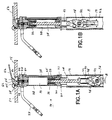
- Fig. 1A is a schematic cross-sectional view of a hydraulic
spike puller incorporating features of the present invention with the
spike contacting section at a down position;
- Fig. 1B is a cross-sectional view as in Fig. 1A with the
spike contacting section at an up position;
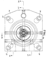
- Fig. 2 is a top plan view of the manifold member used in
the tool shown in Fig. 1A;
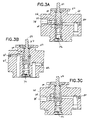
- Fig. 3A is a cross-sectional view taken along line 3A-3A
of Fig. 2;
- Fig. 3B is a cross-sectional view taken along line 3B-3B
of Fig. 2;
- Fig. 3C is a cross-sectional view taken along line 3C-3C
of Fig. 2;
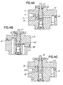
- Fig. 4A is a cross-sectional view as in Fig. 3A with the
valve member depressed;
- Fig. 4B is a cross-sectional view as in Fig. 3B with the
valve member depressed;
- Fig. 4C is a cross-sectional view as in Fig. 3C with the
valve member depressed;
- Fig. 5A is a perspective view of the tool shown in Fig. 1A
next to a railroad rail with its handle in a parallel position relative to
the rail;
- Fig. 5B is a perspective view as in Fig. 5A with the
control lever orientated in a reverse position;
- Fig. 5C is a perspective view as in Fig. 5A with the
handle in a straddle position relative to the rail; and
- Fig. 5D is a perspective view as in Fig. 5C with the
control lever orientated in a reverse position.
-
-
Referring to Fig. 1A there is shown a schematic cross-sectional
view of a tool 10 incorporating features of the present
invention. Although the present invention will be described with
reference to the single embodiment shown in the drawings, it should
be understood that the present invention can be embodied in many
alternate forms of embodiments. In addition, any suitable size, shape
or type of elements or materials could be used.
-
In this embodiment the tool 10 is a hydraulic spike puller
for pulling railroad spikes, such as when a railroad tie or rail is being
replaced. However, in alternate embodiments features of the present
invention could be used in alternative types of tools, such as
pneumatic tools, jack hammers, a ballast tamper or any other tool with
a two-hand handle and control lever assembly. The tool 10 generally
comprises a frame 12, a hydraulic drive section 14, a spike contacting
section 16, and an assembly 18. Referring also to Fig. 5A, a
perspective view of the tool 10 is shown next to a railroad rail A. Fig.
1A shows a portion of a spike B intended to be pulled from a railroad
tie (not shown) by the tool 10.
-
As seen best in Figs. 1A and 5A, the frame 12 generally
comprises a middle section 20, a cover 22, and structural bars 24. The
hydraulic drive section 14 is mounted to the frame 12 by the middle
section 20 and the structural bars 24. The hydraulic drive section 14
generally comprises a manifold member 26, a main tube 28, a bottom
member 30, a piston member 32, a valve member 34, a connecting bar
36, and a supply tube 38. Two hoses 27 (a hydraulic fluid supply hose
and a hydraulic fluid return hose) are connected between the manifold
member 26 and a hydraulic pump (not shown) for supplying hydraulic
fluid to drive the tool 10.
-
As seen best in Fig. 1A, the main tube 28 is connected
between the manifold member 26 and the bottom member 30. The
piston member 32 is movably mounted in a hydraulic fluid relieving
area in the main tube 28 between a down position shown in Fig. 1A
and an up position shown in Fig. 1B. The manifold member 26 has
conduits therethrough. The supply tube 38 is connected between a
conduit 80 in the manifold member 26 and a conduit 40 in the bottom
member 30 which opens into the hydraulic fluid receiving area of the
main tube 28. The connecting member 36 movably extends through the
bottom member 30 and connects the piston member 32 to the spike
contacting section 16. In alternate embodiments other types of drive
sections or hydraulic conducting could be provided.
-
The spike contacting section 16 generally comprises two
tongs 42 pivotably connected to each other. The lower ends of the
tongs 42 are designed to contact the spike B. The upper ends of the
tongs 42 are pivotably connected to the pull member 44 by connecting
links 46. The pull member 44 is connected to the connecting member
36. As seen in comparing Fig. 1A to Fig. 1B, when the pull member 44
is pulled upward, the tongs 42 move towards a grasping position to
grasp onto the spike. In alternate embodiments other types of spike
contacting sections could be provided.
-
The assembly 18 is a combined handle and control
actuator assembly. However, in an alternate embodiment the user
actuated control might be separate from the handle. The assembly 18
generally comprises a cap 48, a handle 50, and a user actuated control
lever 52. The cap 48 is rotatably mounted on a post 54 (see Fig. 3B) of
the manifold member 26. The handle 50 is fixedly attached to the cap
48. In this embodiment the handle 50 is a two-hand "T" type of
handle, but other handle shapes could be used. The lever 52 is
pivotably mounted to the handle 50 in a center groove 56 by a pin 58
at holes 59 in the handle. The handle has another set of holes 60, and
the pin 58 is removable, such that the lever 52 can reverse 180°
relative to the handle to accommodate left hand or right hand users.
The lever 52 has a valve contact area 62 for contacting the top end 64
(see Fig. 3B) of the valve member 34.
-
Referring now to Figs. 2 and 3A-3C, the manifold member
26 comprises four position holes 66 extending into its top side 68. The
valve member 34 is mounted in the center conduit 70. A spring 72
biases the valve member 34 in the up position shown. The valve
member 34 has two annular grooves 74, 76. The manifold member 26
has a first conduit 78, a second conduit 80, a third conduit 82, a fourth
conduit 84, and a fifth conduit 86. In alternate embodiments other
conduit configurations could be provided. The first conduit 78
connects one of the hoses 27 to the center conduit 70. The second
conduit 80 connects the center conduit 70 to the supply tube 38. The
third and fourth conduits 82, 84 connect the center conduit 70 to the
top end of the hydraulic fluid receiving area of the main tube 28. The
fifth conduit 86 connects the center conduit 70 to the other hose 27.
-
With the valve member 34 in the up position shown in
Figs. 3A -3C and the pump (not shown) ON, hydraulic fluid is pumped
into conduit 78, through groove 74, into conduit 84, and into the main
tube 28 to drive the piston 32 down to the position shown in Fig. 1A.
Excess fluid located at the bottom side of the piston 32 in the main
tube 28 is pushed into the conduit 40 (see Fig. 1A), through tube 38,
into conduit 80, through groove 76, and out through the conduit 86.
When the piston 32 is at the down position shown in Fig. 1A, rod
bumpers 33 push the check balls 35 off their sealing seats on the
piston 32 and allow additional fluid entering the main tube 28 to pass
through the piston 32 into conduit 40, through tube 38, into conduit
80, through groove 76 and out conduit 86. The tool is "open center"
with the piston located at this position. Referring now to Figs. 4A- 4C,
the valve member 34 is shown moved down in the center conduit 70.
The valve member 34 is moved down by the user depressing the lever
52 as shown in Fig. 1B. Hydraulic fluid is pumped into conduit 78,
through groove 74, into conduit 80, through supply tube 38 (see Fig.
1B), through conduit 40, and into the main tube 28 on the underside of
the piston 32. This causes the piston 32 to move upward in the main
tube 28, pulling the connecting member 36 and spike contacting
section 16, upward. Fluid on the top side of the piston 32 in the main
tube 28 is transported out of the tool through conduit 82, groove 76,
and conduit 86. The tool is "closed center" when the piston 32 is
moving upward. Check balls 35 are forced into seats in the piston 32
to seal the through holes in the piston at the seats and allow the tool to
reach full operating pressure with high pull force to remove the spike
B. If the user releases the lever 52 the spring 72 biases the spool 34 to
return to a position as shown in Fig. 1A and Fig. 3A. Fluid once again
enters cylinder 28 through conduit 78, groove 74, conduit 84, and into
main tube 28. Fluid flow and pressure push the balls 35 onto their
seats to provide a seal. The balls 35 will remain seated until the
bumper rods 33 strike member 30.
-
Referring now to Figs. 1A and 5A, the cover 22 and spike
contacting section 16 are designed to be placed and orientated relative
to the rail A and spike B as shown. The tool 10 can be rotated 90°
along its longitudinal axis relative to the rail A and still be able to
properly pull out the spike B, however, such an orientation is not
preferred. The preferred orientation is shown in Figs. 5A-5D. Fig. 5A
shows the handle 50 orientated in a parallel position relative to the
rail A. In this position the user would stand facing the rail A with both
feet on one side of the rail A. In Fig. 5A the control lever 52 is shown
in a position over the right hand section 5OR of the handle 50. The
lever 52 is positioned for a right hand user to depress the lever with
his right hand while grasping the right hand section 50R. The hoses 27
are shown extending from the left hand side of the tool 10.
-
Referring now also to Fig. 5B, the same tool is shown in
the same parallel position relative to the rail A. However, the
assembly 18 has been moved to accommodate a left handed user. The
lever 52 is located over the left hand section 50L. In order to
reposition the assembly 18 the cap 48 is rotatable on the manifold
member 26. The assembly 18 has a spring loaded locking pin 90. The
locking pin 90 has a bottom end which can project into one of the
holes 66 (see Fig. 2) in the top side of the manifold member 26. Thus,
the user can lift up the pin 90 from one of the holes 66, rotate the cap
48 on the post 54 (see Fig. 3B) of the manifold member to a new
position, and release the pin 90 to extend back into one of the holes 66
and thereby lock the rotational position of the cap 48 relative to the
manifold member 26 again. In alternate embodiments other types of
means to repositionably mount the assembly 18 to the manifold
member or frame could be provided. The manifold member 26 has four
of the holes 66 which are 90° apart. However, in alternate
embodiments more or less holes could be provided and at any suitable
angular orientation relative to one another. The assembly 18 can be
rotated 360° and locked in place every 90°. This feature, in addition to
allowing left hand and right hand reconfiguration as seen in comparing
Figs. 5A and 5B, can also allow the hoses 27 to be orientated on the
left side or right side of the tool 10.
-
As noted above, the user can also reorientate the lever 52
180° without moving the cap 48 or handle 50. The user can remove the
pin 58 from the holes 59, reorientate the lever 52 in the groove 56,
and then insert the pin 58 into the holes 60 to pivotably mount the
lever 52 at the holes 60. However, repositional mounting of the lever
52 on the handle 50 need not be provided.
-
Referring also to Fig. 5C, the same tool 10 is shown.
However, the assembly 18 has been repositioned into a straddle
configuration with the handle 50 offset 90° from the positions shown
in Figs. 5A and 5B. The handle 50 extends over the rail A and the user
straddles the rail A with his feet; one foot on each opposite side of the
rail A. Fig. 5C shows the assembly 18 at a position for a right hand
user. Fig. 5D shows the same tool 10, but the assembly 18 has been
repositioned 180° for use by a left handed user. Thus, a single tool can
be reconfigured into both a parallel use configuration or a straddle use
configuration relatively easily and simply by the user. A user does not
need to disconnect the section 20 from the bottom member 30 in order
to reconfigure the tool between parallel and straddle use
configurations. The lever 52 is able to actuate the valve member 34 at
any position of the assembly 18 relative to the manifold member 26
because the valve member 34 is centrally located, because the valve
contact area 62 is centrally located, and because the assembly 18 is
rotatably mounted on the same axis that intersects the valve member
34 and contact area 62. In an alternate embodiment the lever 52 could
be mounted to the cap 48 rather than the handle 50, or any suitable
control could be provided connected to any suitable area on the tool.
-
It should be understood that the foregoing description is
only illustrative of the invention. Various alternatives and
modifications can be devised by those skilled in the art without
departing from the invention. Accordingly, the present invention is
intended to embrace all such alternatives, modifications and variances
which fall within the scope of the appended claims.