EP1041305B1 - Embrayage à roue libre - Google Patents
Embrayage à roue libre Download PDFInfo
- Publication number
- EP1041305B1 EP1041305B1 EP00102827A EP00102827A EP1041305B1 EP 1041305 B1 EP1041305 B1 EP 1041305B1 EP 00102827 A EP00102827 A EP 00102827A EP 00102827 A EP00102827 A EP 00102827A EP 1041305 B1 EP1041305 B1 EP 1041305B1
- Authority
- EP
- European Patent Office
- Prior art keywords
- wedge
- annular body
- shaped space
- roller
- way clutch
- Prior art date
- Legal status (The legal status is an assumption and is not a legal conclusion. Google has not performed a legal analysis and makes no representation as to the accuracy of the status listed.)
- Expired - Lifetime
Links
- 230000002093 peripheral effect Effects 0.000 claims description 16
- 230000005540 biological transmission Effects 0.000 description 4
- 230000007423 decrease Effects 0.000 description 3
- 230000007257 malfunction Effects 0.000 description 3
- 238000005096 rolling process Methods 0.000 description 3
- 230000004048 modification Effects 0.000 description 2
- 238000012986 modification Methods 0.000 description 2
- 238000010248 power generation Methods 0.000 description 2
- 238000001816 cooling Methods 0.000 description 1
- 238000004904 shortening Methods 0.000 description 1
- XLYOFNOQVPJJNP-UHFFFAOYSA-N water Substances O XLYOFNOQVPJJNP-UHFFFAOYSA-N 0.000 description 1
Images

Classifications
-
- F—MECHANICAL ENGINEERING; LIGHTING; HEATING; WEAPONS; BLASTING
- F16—ENGINEERING ELEMENTS AND UNITS; GENERAL MEASURES FOR PRODUCING AND MAINTAINING EFFECTIVE FUNCTIONING OF MACHINES OR INSTALLATIONS; THERMAL INSULATION IN GENERAL
- F16D—COUPLINGS FOR TRANSMITTING ROTATION; CLUTCHES; BRAKES
- F16D41/00—Freewheels or freewheel clutches
- F16D41/06—Freewheels or freewheel clutches with intermediate wedging coupling members between an inner and an outer surface
- F16D41/064—Freewheels or freewheel clutches with intermediate wedging coupling members between an inner and an outer surface the intermediate members wedging by rolling and having a circular cross-section, e.g. balls
- F16D41/066—Freewheels or freewheel clutches with intermediate wedging coupling members between an inner and an outer surface the intermediate members wedging by rolling and having a circular cross-section, e.g. balls all members having the same size and only one of the two surfaces being cylindrical
- F16D41/067—Freewheels or freewheel clutches with intermediate wedging coupling members between an inner and an outer surface the intermediate members wedging by rolling and having a circular cross-section, e.g. balls all members having the same size and only one of the two surfaces being cylindrical and the members being distributed by a separate cage encircling the axis of rotation
-
- F—MECHANICAL ENGINEERING; LIGHTING; HEATING; WEAPONS; BLASTING
- F16—ENGINEERING ELEMENTS AND UNITS; GENERAL MEASURES FOR PRODUCING AND MAINTAINING EFFECTIVE FUNCTIONING OF MACHINES OR INSTALLATIONS; THERMAL INSULATION IN GENERAL
- F16D—COUPLINGS FOR TRANSMITTING ROTATION; CLUTCHES; BRAKES
- F16D41/00—Freewheels or freewheel clutches
- F16D41/06—Freewheels or freewheel clutches with intermediate wedging coupling members between an inner and an outer surface
- F16D2041/0608—Races with a regular polygon shape
Definitions
- the present invention relates to a one-way clutch of a type employing rollers according to the preamble of claim 1.
- This one-way clutch is built into a pulley mounted to auxiliary machinery driven by a crankshaft of an engine of an automobile or the like through a belt, for example.
- the U.S.-A-5,482,144 discloses a one-way clutch of the above kind having a cam surface on the inner periphery of an outer rotary ring forming a wedge angle with the outer peripheral surface of an inner ring. Springs are provided to push rollers into the wedge-shaped gaps formed by the inner and outer ring.
- the Japanese unexamined patent publication No. Hei-3-249435 discloses a cam surface of the inner ring being formed as a flat surface, and rollers being provided between the inner ring and the outer ring.
- a conventional one-way clutch of this type will be described.
- An inner annular body and an outer annular body are disposed inside and outside each other in a diameter direction and concentrically with each other.
- Wedge-shaped spaces each with a gap in a diameter direction narrowing in one direction in a circumferential direction are formed at some positions on a circumference in a gap through which both the annular bodies face each other.
- a roller is individually disposed in each the wedge-shaped space. Between both the annular bodies, a cage having pockets extending to open inside and outside in a diameter direction at positions in phase with the wedge-shaped spaces is provided.
- Each roller is individually housed by each corresponding pocket.
- An elastic member is housed by each pocket.
- Each roller is elastically biased by each elastic member toward a narrower side (lock side) in one direction in the circumferential direction in the wedge-shaped space.
- the wedge-shaped spaces are formed by providing cam faces to one of the annular bodies (an outer peripheral face of the inner annular body or an inner peripheral face of the outer annular body) and a wedge angle of the wedge-shaped space is generally set at 9° to 11°.
- the wedge angle is an angle ( ⁇ , ⁇ which will be described later) at which two tangents intersect each other, one of the tangents being a tangent at a point of contact at which the roller contacts the outer peripheral face of the inner annular body and the other of the tangents being a tangent at a point of contact at which the roller contacts the inner peripheral face of the outer annular body when the roller rolls to the lock side.
- the clutch when each the roller rolls to the narrower side in one direction in the circumferential direction of the wedge-shaped space, the clutch is brought into a lock state in which the inner annular body and the outer annular body are integrated with each other through the rollers and rotate synchronously.
- the clutch is brought into a free state in which the inner annular body and the outer annular body rotate with respect to each other. In this manner, depending on a position in the wedge-shaped space to which each the roller rolls, the clutch is switched between the lock state and the free state.
- the one-way clutch according to the invention is characterized by the features of claim 1.
- a one-way clutch including an inner annular body, an outer annular body which is disposed outside the inner annular body and concentrically with the inner annular body and constitutes wedge-shaped spaces at some positions in a circumferential direction between the inner annular body and the outer annular body, each the wedge-shaped space being narrowing in one direction in the circumferential direction, and a plurality of rollers each disposed in each the wedge-shaped space for switching between a lock state in which each the roller rolls to a narrower side of the wedge-shaped space to integrate both the annular bodies with each other to allow both the annular bodies to rotate synchronously and a free state in which each the roller rolls to a wider side of the wedge-shaped space to cancel the lock state to allow both the annular bodies to rotate with respect to each other, wherein the inner annular body and the outer annular body have a structure in which a wedge angle of each the wedge-shaped space is set at 4° to 8°.
- an engagement position of each the roller is at a position in the wedge-shaped space with the narrowest wedge angle and is relatively shallow when the roller is positioned on the narrower side of the wedge-shaped space and gaps between each the roller and both the annular bodies are relatively small when the roller is positioned on the wider side of the wedge-shaped space. Therefore, the rollers move smoothly in switching between the lock state and the free state.
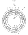
- a one-way clutch according to a preferred embodiment of the present invention will be described below with reference to FIGs. 1 to 4.
- the one-way clutch A has, as its components, an inner ring 1, an outer ring 2, a cage 3, rollers 4, and coil springs 5 as elastic members.
- the roller 4 rolls to a narrower side (lock side) or a wider side (free side) in a wedge-shaped space described later according to a rotation difference between the inner ring 1 and the outer ring 2.
- the inner ring 1 and the outer ring 2 are brought into a lock state in which the inner ring 1 and the outer ring 2 are integrated with each other through the roller 4 and rotate synchronously and power is transmitted.
- the lock state of the inner ring 1 and the outer ring 2 is canceled and the inner ring 1 and the outer ring 2 are brought into a free state in which the inner ring 1 and the outer ring 2 rotate with respect to each other and power transmission is interrupted. In this manner, the inner and outer rings are switched between the lock state and the free state depending on the position to which the roller 4 rolls.
- the inner ring 1 is provided with cam faces 6 constructed of flat key-shaped notches at some positions in a circumferential direction of an inner peripheral face. At two positions facing each other through 180° on one end face of the inner ring 1, slit-shaped notches 1a, 1a are provided.
- the outer ring 2 is formed to have cylindrical inner and outer peripheral faces and disposed concentrically with the inner ring 1 to face an outer periphery of the inner ring 1 through a required gap.
- wedge-shaped spaces are formed at some positions on a circumference in the gap through which the inner ring 1 and outer ring 2 face each other.
- a gap in a diameter direction of each wedge-shaped space is narrow on the lock side on one side in the circumferential direction and wide on the free side on the other side in the circumferential direction.
- the cage 3 is mounted between the inner ring 1 and outer ring 2 and fitted to the outer peripheral face of the inner ring 1.
- the cage 3 has pockets 3a extending to open inside and outside in the diameter direction at positions corresponding to the respective cam faces 6 of the inner ring 1.
- the projecting chips 3c, 3c are fitted into the notches 1a, 1a.
- the cage 3 is positioned in the circumferential direction and the axial direction with respect to the inner ring 1 having the cam faces 6.
- Each the roller 4 is individually housed for rolling in the circumferential direction by the corresponding pocket 3a in the cage 3. In this housed state, each the roller 4 is individually disposed on each the wedge-shaped space formed between the corresponding cam face 6 of the inner ring 1 and the inner peripheral face of the outer ring 2.
- the coil spring 5 is individually housed by the pocket 3a of the cage 3 in a compressed state.
- the coil spring 5 elastically biases the roller 4 toward the narrower side (lock side) in the wedge-shaped space by its extension restoring force.
- the coil spring 5 is fitted to an outside of a projection 3d integrally formed on an inner diameter side on one side of a side wall of a circumferential direction of an inner face of the pocket 3a in the cage 3 such that an expanding/contracting direction (along axis AS) of the coil spring 5 is orthogonal to a rolling axis center of the roller 4 and that one end of the coil spring 5 abuts on an intermediate area in the axial direction of the roller 4 (axis of roller AR).
- the coil spring 5 is an angularly wound spring wound to have a substantially rectangular prism in section and one end of the coil spring 5 in the expanding/contracting direction abuts on a half or more, e.g., two-thirds of a length of the roller in an axial direction at the intermediate area of the roller 4 in the axial direction.
- the coil spring 5 elastically biases the roller 4 toward the inner peripheral face of the outer ring 1 substantially in a direction along the cam face 6 of the inner ring.
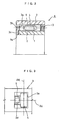
- a wedge angle ⁇ of the wedge-shaped space in the invention is set at 4° to 8°, and preferably at 5° to 7°.
- a lower limit value of the wedge angle ⁇ is set at a value smaller than 4°, a dimensional deviation of the narrower side and the wider side of the wedge-shaped space from each other becomes too small and the roller 4 is liable to remain locked in switching from the lock state to the free state.
- an upper limit value of the wedge angle is set at a value greater than 8°, a dimensional deviation of the narrower side and the wider side of the wedge-shaped space from each other becomes too large and a lock malfunction may occur to delay the switching operation in switching from the free state to the lock state.
- FIG. 4 A difference between the wedge angle ⁇ of the invention and the wedge angle ⁇ of prior art is shown in FIG. 4.
- a solid line and a broken line respectively show the lock state (the narrower side of the wedge-shaped space) and the free state (the wider side of the wedge-shaped space) of the roller 4 in the invention.
- a two-dot dashed line and a one-dot dashed line respectively show the lock state and the free state of the roller 4C in the prior art.
- FIG. 4 is for facilitating understanding of the invention and shows that an engagement position of the roller 4 is shallower in the lock state and gaps between the roller 4 and the inner ring 1 and outer ring 2 are smaller in the free state in the invention as compared with the prior art.
- the roller 4 can move smoothly and stably in switching between the lock state and the free state. Therefore, in the invention, switching of the state is carried out swiftly without delay. Furthermore, in the invention, because the rollers 4 move smoothly, wearing of the inner ring 1 and outer ring 2 which the rollers 4 contact is suppressed.
- coil springs 5 each having a circular shape or a shape of an ellipse of an end face may be used.
- the one-way clutch A of the invention is built in the pulley mounted to auxiliary machinery driven by the crankshaft of the engine of the automobile or the like through the belt, for example.
- auxiliary machinery for which the one-way clutch A of the invention can be used are a compressor for an air conditioner, a water pump, an alternator, a cooling fan, crank pulley, and the like.
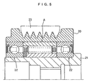
- the one-way clutch A is incorporated into a pulley of an alternator as auxiliary machinery is shown in FIG. 5 and will be described in this case, between the pulley 20 of the alternator and a rotor 21, the one-way clutch A of the above-described embodiment is mounted and rolling bearings 22, 22 such as deep groove ball bearings are disposed on opposite sides of the one-way clutch A in an axial direction.
- the one-way clutch A is switched between the free state and the lock state according to a rotation difference between the pulley 20 and the rotor 21, thereby transmitting rotation power from the pulley 20 to the rotor 21 or interrupting the transmission of the rotation power.
- the one-way clutch A can be functioned such that a rotation speed of the rotor 21 is kept high by an inertial force of the rotor 21 itself when a rotation speed of the pulley 20 decreases, which contributes to improvement of the power generation efficiency.
Landscapes
- Engineering & Computer Science (AREA)
- General Engineering & Computer Science (AREA)
- Mechanical Engineering (AREA)
- Pulleys (AREA)
Claims (3)
- Embrayage à roue libre, comprenant :caractérisé en ce queun corps annulaire intérieur (1) ;un corps annulaire extérieur (2) qui est disposé à l'extérieur dudit corps annulaire intérieur et d'une manière concentrique audit corps intérieur annulaire et constitue des espaces en forme de coins en quelques endroits dans une direction circonférentielle entre ledit corps annulaire intérieur (1) et ledit corps annulaire extérieur (2), chaque dit espace en forme de coin se rétrécissant dans un sens dans ladite direction circonférentielle ;et une pluralité de galets (4) disposés chacun dans ledit espace en forme de coin pour passer d'un état de verrouillage dans lequel chaque dit galet roule vers un côté plus étroit dudit espace en forme de coin afin d'intégrer l'un avec l'autre lesdits deux corps annulaires (1, 2) pour permettre auxdits deux corps annulaires de tourner de manière synchrone, à un état libre dans lequel chaque dit galet roule vers un côté plus large dudit espace en forme de coin afin d'annuler ledit état de verrouillage pour permettre auxdits deux corps annulaires de tourner l'un par rapport à l'autre,
ledit corps annulaire intérieur (1) a des faces de guidage (6) constituées par des encoches planes en forme de clavettes en quelques endroits dans une direction circonférentielle d'une face périphérique extérieure,
ledit corps annulaire extérieur (2) a une face périphérique intérieure à section de forme circulaire,
et chaque dit espace en forme de coin est formé dans un intervalle à travers lequel se font face chaque dite face de guidage (6) dudit corps annulaire intérieur (1) et ladite face périphérique intérieure dudit corps annulaire extérieur,
ledit corps annulaire intérieur (1) et ledit corps annulaire extérieur (2) ont une structure dans laquelle est établi entre 4° et 8° un angle de coin dudit espace en forme de coin, formé par l'angle d'intersection d'un prolongement d'une face de guidage (6) dudit corps annulaire intérieur (1) avec une tangente qui touche la surface circonférentielle intérieure du corps annulaire extérieur (2) au point de contact, où le galet (4) est verrouillé. - Embrayage à roue libre selon la revendication 1, caractérisé par une cage (3) disposée dans un intervalle à travers lequel se font face lesdits deux corps annulaires (1, 2) et ayant des poches correspondant auxdits espaces respectifs en forme de coins et s'étendant pour déboucher à l'intérieur et à l'extérieur dans une direction diamétrale, chaque dite poche contenant individuellement chaque dit galet (4) ;
et des éléments élastiques (5) disposés chacun individuellement dans chaque dite poche pour solliciter de manière élastique ledit galet (4) dans ladite poche vers un côté verrouillage dudit espace en forme de coin. - Embrayage à roue libre selon la revendication 1, caractérisé en ce que les poches (3a) de la cage sont disposées face à face sur 180° de la face périphérique intérieure de la partie de paroi (3b).
Applications Claiming Priority (2)
| Application Number | Priority Date | Filing Date | Title |
|---|---|---|---|
| JP8604399 | 1999-03-29 | ||
| JP08604399A JP4240169B2 (ja) | 1999-03-29 | 1999-03-29 | 一方向クラッチおよび一方向クラッチ内蔵プーリ |
Publications (2)
| Publication Number | Publication Date |
|---|---|
| EP1041305A1 EP1041305A1 (fr) | 2000-10-04 |
| EP1041305B1 true EP1041305B1 (fr) | 2003-07-09 |
Family
ID=13875659
Family Applications (1)
| Application Number | Title | Priority Date | Filing Date |
|---|---|---|---|
| EP00102827A Expired - Lifetime EP1041305B1 (fr) | 1999-03-29 | 2000-02-11 | Embrayage à roue libre |
Country Status (4)
| Country | Link |
|---|---|
| US (1) | US6311814B1 (fr) |
| EP (1) | EP1041305B1 (fr) |
| JP (1) | JP4240169B2 (fr) |
| DE (1) | DE60003740T2 (fr) |
Families Citing this family (6)
| Publication number | Priority date | Publication date | Assignee | Title |
|---|---|---|---|---|
| JP2003021172A (ja) * | 2001-07-10 | 2003-01-24 | Koyo Seiko Co Ltd | 一方向クラッチならびにプーリユニット |
| US6793056B2 (en) * | 2001-07-31 | 2004-09-21 | Ntn Corporation | One-way clutch and one-way clutch assembly |
| TWI224177B (en) * | 2002-01-24 | 2004-11-21 | Honda Motor Co Ltd | One-way clutch |
| JP4262571B2 (ja) * | 2003-10-27 | 2009-05-13 | Hoya株式会社 | 回転力伝達機構 |
| EP2240703A1 (fr) * | 2008-01-14 | 2010-10-20 | Malcolm Tomlinson | Roulement de roue libre/verrouillage retardé et douille de torsion non liée améliorée |
| KR102315302B1 (ko) * | 2016-03-28 | 2021-10-19 | 엔티엔 가부시키가이샤 | 일방향 클러치 |
Family Cites Families (9)
| Publication number | Priority date | Publication date | Assignee | Title |
|---|---|---|---|---|
| FR2582761A1 (fr) | 1985-05-30 | 1986-12-05 | Paris & Du Rhone | Roue libre a effet progressif pour lanceur de demarreurs electriques |
| JPH0765632B2 (ja) | 1986-01-31 | 1995-07-19 | 中部ベアリング株式会社 | ワンウエイクラツチ |
| US4987984A (en) | 1990-01-11 | 1991-01-29 | General Motors Corporation | Cam race for a roller clutch |
| JP2899041B2 (ja) * | 1990-02-28 | 1999-06-02 | エヌティエヌ株式会社 | クラッチ |
| US5482144A (en) | 1994-07-27 | 1996-01-09 | The United States Of America As Represented By The Administrator Of National Aeronautics And Space Administration | Three-dimensional roller locking sprags |
| JP2779331B2 (ja) | 1995-03-08 | 1998-07-23 | バンドー化学株式会社 | エンジン用補機のベルト伝動装置 |
| US5927456A (en) * | 1996-11-01 | 1999-07-27 | Ntn Corporation | Two-way over-running clutch assembly |
| JP3494546B2 (ja) * | 1997-02-25 | 2004-02-09 | 株式会社シマノ | ローラクラッチ |
| JP3785259B2 (ja) * | 1997-09-25 | 2006-06-14 | 株式会社ジェイテクト | プーリユニット |
-
1999
- 1999-03-29 JP JP08604399A patent/JP4240169B2/ja not_active Expired - Fee Related
-
2000
- 2000-02-07 US US09/499,590 patent/US6311814B1/en not_active Expired - Lifetime
- 2000-02-11 DE DE60003740T patent/DE60003740T2/de not_active Expired - Lifetime
- 2000-02-11 EP EP00102827A patent/EP1041305B1/fr not_active Expired - Lifetime
Also Published As
| Publication number | Publication date |
|---|---|
| JP2000283187A (ja) | 2000-10-13 |
| EP1041305A1 (fr) | 2000-10-04 |
| DE60003740T2 (de) | 2004-04-15 |
| JP4240169B2 (ja) | 2009-03-18 |
| DE60003740D1 (de) | 2003-08-14 |
| US6311814B1 (en) | 2001-11-06 |
Similar Documents
| Publication | Publication Date | Title |
|---|---|---|
| US6170625B1 (en) | Pulley unit | |
| US6343682B1 (en) | One-way clutch | |
| EP1262686B1 (fr) | Poulie avec embrayage à roue libre | |
| EP0947722B1 (fr) | Accouplement unidirectionnel | |
| JPH1163025A (ja) | 一方向クラッチ | |
| EP1041305B1 (fr) | Embrayage à roue libre | |
| JP2002106608A (ja) | 一方向クラッチおよびそれを備える動力伝達装置 | |
| JP3811569B2 (ja) | エンジンのクランクシャフト、補機用プーリユニット | |
| JP2005163932A (ja) | プーリユニット | |
| JP3903157B2 (ja) | 一方向クラッチ | |
| JPH1182688A (ja) | プーリユニット | |
| JP2001090750A (ja) | 一方向クラッチ | |
| JP4111556B2 (ja) | エンジンの補機用高速回転プーリユニット | |
| JPH1122753A (ja) | プーリユニット | |
| JPH1163026A (ja) | 一方向クラッチ | |
| JP2001349346A (ja) | 一方向クラッチならびにそれを備えるプーリユニット | |
| JP2005337398A (ja) | 動力伝達装置 | |
| JPH11270596A (ja) | 一方向クラッチ | |
| JP3731704B2 (ja) | プーリユニット | |
| JP2003232386A (ja) | 一方向クラッチおよびプーリ装置 | |
| JP4900162B2 (ja) | トルクリミッター付き一方向クラッチ | |
| JP2000227129A (ja) | 一方向クラッチ | |
| JPH11287260A (ja) | 一方向クラッチ | |
| JP5045996B2 (ja) | 一方向クラッチ | |
| JPH11280873A (ja) | プーリ |
Legal Events
| Date | Code | Title | Description |
|---|---|---|---|
| PUAI | Public reference made under article 153(3) epc to a published international application that has entered the european phase |
Free format text: ORIGINAL CODE: 0009012 |
|
| 17P | Request for examination filed |
Effective date: 20000712 |
|
| AK | Designated contracting states |
Kind code of ref document: A1 Designated state(s): DE FR GB IT |
|
| AX | Request for extension of the european patent |
Free format text: AL;LT;LV;MK;RO;SI |
|
| 17Q | First examination report despatched |
Effective date: 20010313 |
|
| AKX | Designation fees paid |
Free format text: DE FR GB IT |
|
| GRAH | Despatch of communication of intention to grant a patent |
Free format text: ORIGINAL CODE: EPIDOS IGRA |
|
| GRAH | Despatch of communication of intention to grant a patent |
Free format text: ORIGINAL CODE: EPIDOS IGRA |
|
| GRAA | (expected) grant |
Free format text: ORIGINAL CODE: 0009210 |
|
| AK | Designated contracting states |
Designated state(s): DE FR GB IT |
|
| REG | Reference to a national code |
Ref country code: GB Ref legal event code: FG4D |
|
| REF | Corresponds to: |
Ref document number: 60003740 Country of ref document: DE Date of ref document: 20030814 Kind code of ref document: P |
|
| ET | Fr: translation filed | ||
| PLBE | No opposition filed within time limit |
Free format text: ORIGINAL CODE: 0009261 |
|
| STAA | Information on the status of an ep patent application or granted ep patent |
Free format text: STATUS: NO OPPOSITION FILED WITHIN TIME LIMIT |
|
| 26N | No opposition filed |
Effective date: 20040414 |
|
| PGFP | Annual fee paid to national office [announced via postgrant information from national office to epo] |
Ref country code: FR Payment date: 20140211 Year of fee payment: 15 |
|
| PGFP | Annual fee paid to national office [announced via postgrant information from national office to epo] |
Ref country code: IT Payment date: 20150218 Year of fee payment: 16 |
|
| PGFP | Annual fee paid to national office [announced via postgrant information from national office to epo] |
Ref country code: GB Payment date: 20150211 Year of fee payment: 16 |
|
| REG | Reference to a national code |
Ref country code: FR Ref legal event code: ST Effective date: 20151030 |
|
| PG25 | Lapsed in a contracting state [announced via postgrant information from national office to epo] |
Ref country code: FR Free format text: LAPSE BECAUSE OF NON-PAYMENT OF DUE FEES Effective date: 20150302 |
|
| GBPC | Gb: european patent ceased through non-payment of renewal fee |
Effective date: 20160211 |
|
| PG25 | Lapsed in a contracting state [announced via postgrant information from national office to epo] |
Ref country code: IT Free format text: LAPSE BECAUSE OF NON-PAYMENT OF DUE FEES Effective date: 20160211 |
|
| PG25 | Lapsed in a contracting state [announced via postgrant information from national office to epo] |
Ref country code: GB Free format text: LAPSE BECAUSE OF NON-PAYMENT OF DUE FEES Effective date: 20160211 |
|
| PGFP | Annual fee paid to national office [announced via postgrant information from national office to epo] |
Ref country code: DE Payment date: 20190129 Year of fee payment: 20 |
|
| REG | Reference to a national code |
Ref country code: DE Ref legal event code: R071 Ref document number: 60003740 Country of ref document: DE |