EP1041377A2 - Probennehmer und Verfahren zur Erlangung der Grössenverteilung von Aerosolteilchen - Google Patents
Probennehmer und Verfahren zur Erlangung der Grössenverteilung von Aerosolteilchen Download PDFInfo
- Publication number
- EP1041377A2 EP1041377A2 EP20000105590 EP00105590A EP1041377A2 EP 1041377 A2 EP1041377 A2 EP 1041377A2 EP 20000105590 EP20000105590 EP 20000105590 EP 00105590 A EP00105590 A EP 00105590A EP 1041377 A2 EP1041377 A2 EP 1041377A2
- Authority
- EP
- European Patent Office
- Prior art keywords
- sampler
- gas
- particles
- flow
- sampler according
- Prior art date
- Legal status (The legal status is an assumption and is not a legal conclusion. Google has not performed a legal analysis and makes no representation as to the accuracy of the status listed.)
- Withdrawn
Links
Images


Classifications
-
- B—PERFORMING OPERATIONS; TRANSPORTING
- B01—PHYSICAL OR CHEMICAL PROCESSES OR APPARATUS IN GENERAL
- B01D—SEPARATION
- B01D46/00—Filters or filtering processes specially modified for separating dispersed particles from gases or vapours
- B01D46/0027—Filters or filtering processes specially modified for separating dispersed particles from gases or vapours with additional separating or treating functions
- B01D46/003—Filters or filtering processes specially modified for separating dispersed particles from gases or vapours with additional separating or treating functions including coalescing means for the separation of liquid
-
- B—PERFORMING OPERATIONS; TRANSPORTING
- B01—PHYSICAL OR CHEMICAL PROCESSES OR APPARATUS IN GENERAL
- B01D—SEPARATION
- B01D46/00—Filters or filtering processes specially modified for separating dispersed particles from gases or vapours
- B01D46/10—Particle separators, e.g. dust precipitators, using filter plates, sheets or pads having plane surfaces
- B01D46/12—Particle separators, e.g. dust precipitators, using filter plates, sheets or pads having plane surfaces in multiple arrangements
-
- G—PHYSICS
- G01—MEASURING; TESTING
- G01N—INVESTIGATING OR ANALYSING MATERIALS BY DETERMINING THEIR CHEMICAL OR PHYSICAL PROPERTIES
- G01N1/00—Sampling; Preparing specimens for investigation
- G01N1/02—Devices for withdrawing samples
- G01N1/22—Devices for withdrawing samples in the gaseous state
- G01N1/2202—Devices for withdrawing samples in the gaseous state involving separation of sample components during sampling
- G01N1/2205—Devices for withdrawing samples in the gaseous state involving separation of sample components during sampling with filters
-
- B—PERFORMING OPERATIONS; TRANSPORTING
- B01—PHYSICAL OR CHEMICAL PROCESSES OR APPARATUS IN GENERAL
- B01D—SEPARATION
- B01D2275/00—Filter media structures for filters specially adapted for separating dispersed particles from gases or vapours
- B01D2275/30—Porosity of filtering material
-
- G—PHYSICS
- G01—MEASURING; TESTING
- G01N—INVESTIGATING OR ANALYSING MATERIALS BY DETERMINING THEIR CHEMICAL OR PHYSICAL PROPERTIES
- G01N15/00—Investigating characteristics of particles; Investigating permeability, pore-volume or surface-area of porous materials
- G01N15/02—Investigating particle size or size distribution
- G01N15/0272—Investigating particle size or size distribution with screening; with classification by filtering
-
- G—PHYSICS
- G01—MEASURING; TESTING
- G01N—INVESTIGATING OR ANALYSING MATERIALS BY DETERMINING THEIR CHEMICAL OR PHYSICAL PROPERTIES
- G01N1/00—Sampling; Preparing specimens for investigation
- G01N1/02—Devices for withdrawing samples
- G01N1/22—Devices for withdrawing samples in the gaseous state
- G01N1/2202—Devices for withdrawing samples in the gaseous state involving separation of sample components during sampling
- G01N2001/222—Other features
- G01N2001/2223—Other features aerosol sampling devices
-
- G—PHYSICS
- G01—MEASURING; TESTING
- G01N—INVESTIGATING OR ANALYSING MATERIALS BY DETERMINING THEIR CHEMICAL OR PHYSICAL PROPERTIES
- G01N30/00—Investigating or analysing materials by separation into components using adsorption, absorption or similar phenomena or using ion-exchange, e.g. chromatography or field flow fractionation
- G01N30/02—Column chromatography
- G01N30/04—Preparation or injection of sample to be analysed
- G01N30/06—Preparation
Definitions
- This invention relates to a particle sampler and method for obtaining size distributions of aerosol particles.
- the distribution of sizes of aerosol particles in a gas can be of interest in many technical fields, including pollution monitoring.
- Any method of establishing the size distribution of aerosol particles has a lower limit on the size of particle which can be detected. It is advantageous for this lower limit to be as small as possible, so that an accurate distribution can be obtained.
- a known method for establishing the size distribution of aerosol particles is based on the deposition of particles onto substrates in a cascade impactor, and analysis of the deposits.
- a cascade impactor particles of different sizes are collected onto different substrates due to the differences in their inertia. This is achieved by means of a number of air jets with specific characteristics, each stage of a cascade impactor having a different jet facing the substrate.
- Cascade impactors have good resolution, but the lower limit of the size of particle detectable is around 0.3 ⁇ m.
- Another known method for establishing the size distribution of aerosol particles is the deposition of particles onto a fibre or filter membrane.
- the fibre or membrane is then analysed. This is a simple method, but the information that can be derived about particle sizes is limited.
- various size selective inlets are used along with the fibre or membrane to obtain the mass fraction of a certain size of particle. This method allows a wide range of particle sizes to be detected, however the resolution is quite poor.
- the present invention provides a sampler for collecting aerosol particles from a flow of gas containing aerosol particles, which sampler has an inlet and an outlet and a collector having a plurality of collection regions onto which particles of predetermined sizes are collectable so that different sized particles are collected at different collection regions, each collection region comprising a porous medium.
- the sampler includes a size selective inlet.
- the collector includes at least one net which is placed across the flow of gas.
- the collector comprises a series of spaced apart nets.
- the gaps between the fibres of the net adjacent the inlet are larger than the gaps between the net adjacent the outlet.
- At least one of the nets is a composite of two or more nets.
- the nets are substantially orthogonal to the flow of gas.
- the collector includes at least one region of an internal surface of the sampler.
- the internal surface is divisible into removable regions.
- the collector includes at least one substantially planar surface which is not an internal surface of the sampler.
- the sampler includes a series of parallel and spaced apart planar surfaces.
- the surfaces are arranged substantially parallel to the flow of gas.
- the surfaces are elongate.
- the surfaces are divisible into removable regions.
- At least a part of the sampler is inclined at an angle to the horizontal.
- the collector includes at least one capillary.
- the inlet includes a variable diameter aperture through which the flow of gas is directed, to control the rate of the flow of gas.
- the sampler includes a particle detector, through which the flow of gas is directed.
- the particle detector is a cascade impactor.
- Another aspect of the present invention provides a method of determining the size distribution of aerosol particles in a gas, comprising the step of: passing the gas through a sampler, which sampler has an inlet and an outlet and a collector having a plurality of collection regions onto which particles of predetermined sizes are collectable so that different sized particles are collected at different collection regions.
- the gas leaving the sampler through the outlet is analysed.
- deconvolution is employed to determine the size distribution of particles in the gas.
- a further aspect of the present invention provides a method of determining the size distribution of aerosol particles, utilising any sampler described above, wherein gas containing aerosol particles is retained in the sampler for a predetermined time period, and the sampler is subsequently analysed.
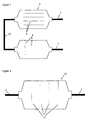
- a known filter sampler 1 consists of an enclosed volume, which has an inlet 2 and an outlet 3, and a single filter 4 positioned between these.
- gas containing aerosol particles flows in through the inlet 2 and out through the outlet 3, passing through the filter 4.
- Particles are retained by the filter 4, and this filter 4 can be removed after operation of the sampler 1 and analysed.
- This type of sampler 1 does not provide information about the size distribution of the aerosol particles, as all particles are retained at the same location.
- FIG 2 shows a sampler 5 embodying the present invention.
- the sampler 5 consists of an elongate enclosed volume which has an inlet 2 at one end, an outlet 3 at the opposite end and a series of nets 6 which are spaced apart from one another at regular intervals along the length of the sampler volume.
- the nets 6 are arranged vertically and substantially orthogonal to the direction of gas flow through the sampler. Each net 6 is designed to retain a different size of aerosol particle.
- the flow of gas through the sampler 5 (and through all of the embodiments in the Figures) is established by means of a pump (not shown), which may be positioned before or after the sampler 5.
- Aerosol particles of different sizes have different collision efficiencies, the smallest particles having the highest collision efficiencies. This means that smaller particles are more likely to be moved towards fibres of a net 6 and be captured by the net.
- the first net 6, therefore, has the lowest density of fibres and therefore the largest gaps between fibres, and is designed to retain the smallest particles.
- Subsequent nets 6 have progressively higher densities of fibres, and are designed to retain progressively larger particles.
- Mesh opening of screen ( ⁇ m) Sizes of particles collected (nm) First net 180 1 - 15 Second net 41 15 - 40 Third net 41 (3 net composite) 40 - 150 Fourth net 20 150 - 300
- any of the nets may be a composite of one or more other nets.
- the rate of flow through the sampler is constant at 20 litres per minute or less, and the humidity of the sampler is around 80%.
- a flow of gas containing particles is established through the sampler 5 for a predetermined time period at a predetermined flow rate.
- the nets 6 can be individually removed and analysed.
- the size distribution of aerosol particles in the gas which flowed through the sampler 5 is obtained by conventional deconvolution methods. Using such methods, a lower limit of 1 nm of the size of particle that is detected can be achieved.
- Methods of analysing the deposits on the nets 6 include atomic absorption spectroscopy, gas chromatography, gas chromatography with a mass spectrometer sensor, high performance liquid chromatography, gravimetrical analysis, and any chemical analysis.
- FIG 3 shows another sampler 7 embodying the present invention
- the sampler 7 includes two enclosed volumes, one of which is an elongate sedimentation cell 8 having an inlet 2 and the other of which comprises the sampler 5 of Figure 2 having an outlet 3, the two volumes being connected together by a tube 10.
- the sedimentation cell 8 encloses a number of parallel spaced apart and substantially horizontal planar surfaces 9 arranged to lie substantially parallel to the gas flow in the sedimentation cell 8.
- the planar surfaces are porous.
- the outlet from the sedimentation cell 8 leads through the tube 10 to the inlet of the second enclosed volume, the sampler 5 of Figure 2.
- a flow of gas containing particles is established through the sampler 5 for a predetermined time period at a predetermined flow rate.
- the horizontal surfaces 9 will collect different sized particles at different locations along their lengths, as larger particles will tend to settle more easily on these surfaces and so will settle nearer the inlet 2 than lighter particles. Particles which are too light to settle on the surfaces 9 at all will be carried through the tube 10 into the second volume and will be retained by the nets 6.
- the surfaces 9 and the nets 6 can be removed and analysed. Any of the analysis methods mentioned above in relation to the sampler 5 of Figure 2 may also be used to analyse the deposits on the surfaces 9. Any of the surfaces 9 may be splittable along its length into shorter sections, to facilitate individual analysis of each divided section.
- FIG 4 shows another sampler 11 embodying the present invention.
- This sampler 11 includes an enclosed volume which has a series of capillaries 12.
- the capillaries 12 comprise a porous medium into which particles can enter and be retained.
- deconvolution methods need to be used to calculate the size distribution of the aerosol particles.
- FIG. 5 shows a further sampler 13 embodying the present invention.
- the sampler 13 is similar to the previously described sampler 8 containing parallel porous surfaces 9, although in this embodiment the entire sampler 13 is inclined at an angle of approximately 45°, so that the inlet 2 is higher than the outlet 3.
- the concentration of particle sizes will vary along the length of the parallel surfaces 9 such that different regions of the same parallel surface 9 will have different concentrations of respective particle sizes
- Figure 6 shows a further sampler 14 embodying the present invention, which consists of a cylinder 15 having an inlet 2 and an outlet 3. Gas containing aerosol particles passes through the cylinder, and particles will settle on an internal lining or surface of the cylinder 15.
- the internal lining or surface is porous.
- heavier particles will tend to settle nearer the inlet 2 than lighter ones.
- the internal surface of the cylinder 15 can be analysed.
- the lining or internal surface is nominally divided into discrete regions along its length such that each region will provide an indication of the concentrations of particle sizes.
- the internal surface may be physically divided along its length so that individual regions can be analysed separately.
- FIG 7 shows another sampler 16 embodying the present invention, which can be used to determine the size distribution of aerosol particles.
- the apparatus comprises a sedimentation cell 8 defining an enclosed volume with an inlet 2 and an outlet 3, and horizontal porous surfaces 9 as described above in relation to Figure 3, with the difference that the conditions in the volume (e.g. flow rate, humidity, configuration of surfaces 9) are such that not all aerosol particles will be retained by the surfaces 9.
- the apparatus also includes an optical sensor 17 (e.g. an AMS9501S, manufactured by Casella) which is connected to the outlet, and which counts the particles passing through it.
- an optical sensor 17 e.g. an AMS9501S, manufactured by Casella
- This apparatus can be used repeatedly, with different operating conditions in the volume (e.g. a different rate of flow, or surfaces with different lengths). For each set of conditions, the number of particles passing out of the volume without being retained by the surfaces 9 can be measured, and after repeated readings with appropriate different conditions, deconvolution methods can be used to determine the size distribution of the aerosol particles.
- different operating conditions in the volume e.g. a different rate of flow, or surfaces with different lengths.
- the sampler of Figure 7 can also be used in conjunction with a 'stop-flow' technique, wherein gas flows through the volume and then the flow of gas through the volume is stopped for a "no-flow" period. During this period, particles above a certain collision efficiency will be retained on the porous surfaces 9 and particles below the certain collision efficiency will not be retained. This critical collision efficiency will depend on the conditions in the volume, as well as the length of the no-flow period. After the no-flow period, the flow of gas can be restored, and the gas leaving the volume can be analysed, or the porous surfaces 9 can be removed and analysed.
Landscapes
- Chemical & Material Sciences (AREA)
- Chemical Kinetics & Catalysis (AREA)
- Health & Medical Sciences (AREA)
- Life Sciences & Earth Sciences (AREA)
- Engineering & Computer Science (AREA)
- Biomedical Technology (AREA)
- Molecular Biology (AREA)
- Physics & Mathematics (AREA)
- Analytical Chemistry (AREA)
- Biochemistry (AREA)
- General Health & Medical Sciences (AREA)
- General Physics & Mathematics (AREA)
- Immunology (AREA)
- Pathology (AREA)
- Sampling And Sample Adjustment (AREA)
Applications Claiming Priority (2)
| Application Number | Priority Date | Filing Date | Title |
|---|---|---|---|
| GB9906185 | 1999-03-17 | ||
| GB9906185A GB2347879A (en) | 1999-03-17 | 1999-03-17 | Aerosol sampling filter |
Publications (1)
| Publication Number | Publication Date |
|---|---|
| EP1041377A2 true EP1041377A2 (de) | 2000-10-04 |
Family
ID=10849838
Family Applications (1)
| Application Number | Title | Priority Date | Filing Date |
|---|---|---|---|
| EP20000105590 Withdrawn EP1041377A2 (de) | 1999-03-17 | 2000-03-16 | Probennehmer und Verfahren zur Erlangung der Grössenverteilung von Aerosolteilchen |
Country Status (2)
| Country | Link |
|---|---|
| EP (1) | EP1041377A2 (de) |
| GB (1) | GB2347879A (de) |
Cited By (3)
| Publication number | Priority date | Publication date | Assignee | Title |
|---|---|---|---|---|
| WO2004003520A1 (en) * | 2002-06-28 | 2004-01-08 | Wras Technology Limited | Two-stage particle-size analyser |
| CN102323116A (zh) * | 2011-10-11 | 2012-01-18 | 山东大学 | 一种沉降式气溶胶采样器 |
| US9810606B2 (en) | 2016-02-01 | 2017-11-07 | Src, Inc. | Methods and devices for vapor sampling |
Families Citing this family (4)
| Publication number | Priority date | Publication date | Assignee | Title |
|---|---|---|---|---|
| GB2371499B (en) * | 2001-01-24 | 2003-12-17 | Aea Technology Plc | Aerosol Monitoring |
| GB0513358D0 (en) * | 2005-06-29 | 2005-08-03 | Gorbounon Boris | Portable nanoparticle size classifier |
| US11740161B2 (en) | 2017-12-07 | 2023-08-29 | The Governors Of The University Of Alberta | Filters for mimicking regional lung deposition |
| LT7009B (lt) | 2021-12-10 | 2023-07-25 | Kauno technologijos universitetas | Polimerinių pluoštinių matricų formavimo būdas ir tokiu būdu gauta pluošto matrica |
Family Cites Families (5)
| Publication number | Priority date | Publication date | Assignee | Title |
|---|---|---|---|---|
| SU837375A1 (ru) * | 1979-09-07 | 1981-06-15 | Предприятие П/Я В-2343 | Фильтр дл отбора проб |
| GB2120392B (en) * | 1982-04-22 | 1986-02-26 | Atomic Energy Authority Uk | The measurement of the sizes of particulate matter dispersed in an aerosol |
| EP0227679A1 (de) * | 1984-09-26 | 1987-07-08 | ANDERSSON, Jan Peter | Verfahren und vorrichtung zum auffangen und analysieren von teilchen |
| JPH0254146A (ja) * | 1988-08-18 | 1990-02-23 | Kagaku Gijutsucho Hoshasen Igaku Sogo Kenkyusho | エアロゾル粒子径分布の測定方法及び装置 |
| US5702506A (en) * | 1996-10-16 | 1997-12-30 | Institute Of Occupational Safety And Health, Council Of Labor Affairs, Executive Yuan | Method and device for aerosol size-selective sampling |
-
1999
- 1999-03-17 GB GB9906185A patent/GB2347879A/en not_active Withdrawn
-
2000
- 2000-03-16 EP EP20000105590 patent/EP1041377A2/de not_active Withdrawn
Cited By (5)
| Publication number | Priority date | Publication date | Assignee | Title |
|---|---|---|---|---|
| WO2004003520A1 (en) * | 2002-06-28 | 2004-01-08 | Wras Technology Limited | Two-stage particle-size analyser |
| GB2407171A (en) * | 2002-06-28 | 2005-04-20 | Wras Technology Ltd | Two-stage particle-size analyser |
| GB2407171B (en) * | 2002-06-28 | 2005-12-14 | Wras Technology Ltd | Particle collector |
| CN102323116A (zh) * | 2011-10-11 | 2012-01-18 | 山东大学 | 一种沉降式气溶胶采样器 |
| US9810606B2 (en) | 2016-02-01 | 2017-11-07 | Src, Inc. | Methods and devices for vapor sampling |
Also Published As
| Publication number | Publication date |
|---|---|
| GB2347879A (en) | 2000-09-20 |
| GB9906185D0 (en) | 1999-05-12 |
Similar Documents
| Publication | Publication Date | Title |
|---|---|---|
| US7578973B2 (en) | Devices for continuous sampling of airborne particles using a regenerative surface | |
| US3983743A (en) | Apparatus and method for the analysis of a particle-laden gas | |
| Marple et al. | Low flow rate sharp cut impactors for indoor air sampling: design and calibration | |
| CA1191459A (en) | Mist separator | |
| US5401468A (en) | Dual flow path carbon particulate monitor | |
| US5196170A (en) | Carbon particulate monitor | |
| WO1998058725A1 (en) | Apparatus for separation and concentration of particles from a fluid stream | |
| EP0696934A4 (de) | Virtueller impaktor und arbeitsmethode | |
| CN108318394B (zh) | 一种微流控分选测量可吸入颗粒物的方法及装置 | |
| Collett Jr et al. | A three-stage cloud impactor for size-resolved measurement of cloud drop chemistry | |
| Haglund et al. | A circumferential slot virtual impactor | |
| EP1041377A2 (de) | Probennehmer und Verfahren zur Erlangung der Grössenverteilung von Aerosolteilchen | |
| DE69318357T2 (de) | Aerosol-Sammler | |
| Prodi et al. | An inertial spectrometer for aerosol particles | |
| US7610793B2 (en) | Residence time chamber and sampling apparatus | |
| Tolocka et al. | On the modification of the low flow-rate PM10 dichotomous sampler inlet | |
| Büttner | Size separation of particles from aerosol samples using impactors and cyclones | |
| US20060081515A1 (en) | Two-stage particle-size analyzer | |
| CN106092669B (zh) | 一种基于粒径的栅格分级分离空气中颗粒物的方法和装置 | |
| CN106290085A (zh) | 一种基于粒径的栅格分级筛选空气中颗粒物的方法和装置 | |
| AU2789392A (en) | Method and apparatus for sampling air contaminants | |
| US20250264382A1 (en) | System and Method to Control Particle Deposition on a Filter Membrane | |
| Straub et al. | Numerical and experimental performance evaluation of the 3-stage FROSTY Supercooled Cloud Collector | |
| Slowik et al. | Analysis of cloud condensation nuclei composition and growth kinetics using a pumped counterflow virtual impactor and aerosol mass spectrometer | |
| Marshall et al. | The calibration of a Timbrell aerosol spectrometer |
Legal Events
| Date | Code | Title | Description |
|---|---|---|---|
| PUAI | Public reference made under article 153(3) epc to a published international application that has entered the european phase |
Free format text: ORIGINAL CODE: 0009012 |
|
| AK | Designated contracting states |
Kind code of ref document: A2 Designated state(s): AT BE CH CY DE DK ES FI FR GB GR IE IT LI LU MC NL PT SE |
|
| AX | Request for extension of the european patent |
Free format text: AL;LT;LV;MK;RO;SI |
|
| STAA | Information on the status of an ep patent application or granted ep patent |
Free format text: STATUS: THE APPLICATION IS DEEMED TO BE WITHDRAWN |
|
| 18D | Application deemed to be withdrawn |
Effective date: 20021001 |