EP1041685A1 - Abgabevorrichtung für Zubehörteile von elektrischen Kabeln und Ladevorrichtung - Google Patents
Abgabevorrichtung für Zubehörteile von elektrischen Kabeln und Ladevorrichtung Download PDFInfo
- Publication number
- EP1041685A1 EP1041685A1 EP00400810A EP00400810A EP1041685A1 EP 1041685 A1 EP1041685 A1 EP 1041685A1 EP 00400810 A EP00400810 A EP 00400810A EP 00400810 A EP00400810 A EP 00400810A EP 1041685 A1 EP1041685 A1 EP 1041685A1
- Authority
- EP
- European Patent Office
- Prior art keywords
- box according
- shells
- nesting
- dispensing
- dispensing box
- Prior art date
- Legal status (The legal status is an assumption and is not a legal conclusion. Google has not performed a legal analysis and makes no representation as to the accuracy of the status listed.)
- Granted
Links
- 230000000295 complement effect Effects 0.000 claims description 8
- 238000003856 thermoforming Methods 0.000 claims description 3
- 238000004026 adhesive bonding Methods 0.000 claims description 2
- 238000003466 welding Methods 0.000 claims description 2
- 238000005553 drilling Methods 0.000 claims 1
- 238000002788 crimping Methods 0.000 description 4
- 239000004020 conductor Substances 0.000 description 3
- 239000002184 metal Substances 0.000 description 3
- 239000002390 adhesive tape Substances 0.000 description 1
- 230000000694 effects Effects 0.000 description 1
- 239000011810 insulating material Substances 0.000 description 1
- 238000002955 isolation Methods 0.000 description 1
- 238000012423 maintenance Methods 0.000 description 1
- 238000011084 recovery Methods 0.000 description 1
Images

Classifications
-
- H—ELECTRICITY
- H01—ELECTRIC ELEMENTS
- H01R—ELECTRICALLY-CONDUCTIVE CONNECTIONS; STRUCTURAL ASSOCIATIONS OF A PLURALITY OF MUTUALLY-INSULATED ELECTRICAL CONNECTING ELEMENTS; COUPLING DEVICES; CURRENT COLLECTORS
- H01R43/00—Apparatus or processes specially adapted for manufacturing, assembling, maintaining, or repairing of line connectors or current collectors or for joining electric conductors
- H01R43/04—Apparatus or processes specially adapted for manufacturing, assembling, maintaining, or repairing of line connectors or current collectors or for joining electric conductors for forming connections by deformation, e.g. crimping tool
- H01R43/042—Hand tools for crimping
- H01R43/045—Hand tools for crimping with contact member feeding mechanism
-
- H—ELECTRICITY
- H02—GENERATION; CONVERSION OR DISTRIBUTION OF ELECTRIC POWER
- H02G—INSTALLATION OF ELECTRIC CABLES OR LINES, OR OF COMBINED OPTICAL AND ELECTRIC CABLES OR LINES
- H02G3/00—Installations of electric cables or lines or protective tubing therefor in or on buildings, equivalent structures or vehicles
Definitions
- the present invention relates generally to the distribution of wiring accessories to a tool specific to the implementation of these.
- the present invention relates to the distribution of such wiring accessories to a crimping tool, or, in other words, supplying the latter with such wiring accessories.
- This crimping tool can for example be of the type described in the French patent which, filed on February 5, 1988, under No. 88 01355, was published under No. 2 626 803.
- this is a clamp whose supply of accessories for wiring is done using a rectilinear charger, i.e. using a charger suitable for receiving an alignment of these wiring accessories, that these are placed there in the form of a band within which they are successively linked to each other, or that they are set up there individually one after the other.
- the present invention generally relates to a provision to significantly increase this capacity if longed for.
- the present invention firstly relates to a distribution box for wiring accessories, especially for ferrules of wiring, characterized in that it is formed by two shells, which are facing each other along a common joint surface, being duly subject to each other, and jointly delimiting one with the other a reception volume specific to the housing of the wiring accessories to distribute, and in that it includes, externally, an element socket, such as projecting rib or hollow groove, suitable for allow it to be reported on any other equipment, with, distance from this nesting element, a clean opening for the passage of wiring accessories.
- an element socket such as projecting rib or hollow groove
- the dispenser box according to the invention can for example be brought on a straight loader, increasing thus advantageously the capacity thereof.
- this charger is equipped with an element complementary nesting of its own nesting element.
- the present invention therefore, from this point of view, still relates to any charger which, normally suitable for receiving a simple alignment of wiring accessories, comprises, externally, such an element complementary nesting.
- the two shells of the dispenser box according to the invention are in one piece with one another, being articulated to each other by a hinge area.
- the assembly is produced by thermoforming.
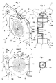
- FIGS. 1-10 illustrate, by way of example, the application of the invention to case where the wiring accessories 10 to be distributed are cable end caps comprising, on the one hand, a metal barrel 11, intended to be engaged, and crimped, on the end, previously stripped, of the conductive core of any electrical conductor not shown, and, on the other hand, a flange in insulating material 12, intended to be engaged on the sheath of this electrical conductor.
- cable end caps comprising, on the one hand, a metal barrel 11, intended to be engaged, and crimped, on the end, previously stripped, of the conductive core of any electrical conductor not shown, and, on the other hand, a flange in insulating material 12, intended to be engaged on the sheath of this electrical conductor.
- the wiring accessories 10 to be distributed form a strip 13, continuous, at the within which they are successively articulated to each other so detachable, and which by itself is flexible enough to be wound in a spiral, like a roll.
- a distributor box 14 for the housing, and the recovery, of accessories wiring 10 thus forming a roll, it is implemented a distributor box 14.
- this distributor box 14 is generally formed by two shells 14A, 14B, which face each other at the other along a joint surface S common to both of them them, being duly subject to each other according to provisions described in more detail later, and jointly delimiting one with the other a receiving volume V specific to the housing of the accessories of wiring 10 to be distributed, and, according to arrangements also described more in detail later, it has, externally, an element socket 16, such as projecting rib or hollow groove, suitable for allow it to be reported on any other equipment, with, distance from this nesting element 16, an opening 17 specific to the passage of wiring accessories 10.
- an element socket 16 such as projecting rib or hollow groove
- the two shells 14A, 14B are articulated to each other by a hinge zone Z, and this forms by itself the interlocking element 16.
- the reception volume V formed by the two shells 14A, 14B is generally cylindrical.
- this reception volume V extends annularly around a central hole 18 suitable for allowing the passage of a spindle when filled with wiring accessories 10.
- the outer periphery of this volume V has a generally octagonal outline, and its internal periphery has a generally circular outline.
- the central hole 18 is lined half by each of the shells 14A, 14B.
- the two shells 14A, 14B each, respectively, around the reception volume V, on a at least part of the periphery thereof, two flanges 20A, 20B, which extend substantially perpendicular to the axis A of this volume of reception V, and which, joined together, define the joint surface S of these two shells 14A, 14B, so that this joint surface S is flat.
- the nesting element 16 extends longitudinally along one of the edges of the flanges 20A, 20B of the two shells 14A, 14B, away from the receiving volume V, and substantially orthogonally to the axis A of it.
- this interlocking element 16 extends on either side of the joint surface S of the two shells 14A, 14B, being distributed so half on each of these.
- the nesting element 16 forms a projecting rib, and, having a leg 21 and a head 22, it has, transversely, an overall T profile.
- the jamb 21 of this interlocking element 16 is reduced to a portion of the flanges 20A, 20B of the two shells 14A, 14B.
- the longitudinal sides 23A, 23B of the head 22 of the element socket 16 are oblique to each other, approaching from each other as they move away from the jamb 21 of this socket element 16.
- the head 22 of the interlocking element 16 has, transversely, an overall profile generally trapezoidal.
- the opening 17 of the box distributor 14 intervenes on the tranche of the reception volume V, at the outer periphery of it.
- this opening 17 extends in the immediate vicinity of the interlocking element 16, and, like this, it is distributed half over each of the two shells 14A, 14B.
- this opening 17 results from notches 25A, 25B each locally affecting the shells 14A, 14B respectively extending symmetrically over one and the other of these.
- the flange 20A, 20B of at least one of the two shells 14A, 14B has, at the edge of the opening 17, a bore 26 suitable for the engagement of a wiring accessory 10 by the metal barrel 11 of this one.
- the bore 26 extends at a level intermediate between that of the fitting element 16 and that of the opening 17.
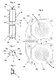
- the two shells 14A, 14B are subject to each other by nesting zones E which intervene from place to place around the reception volume V.
- V ' which, formed at this location by the two shells 14A, 14B for the local stiffening of the assembly, locally skirts the volume of reception V.
- each of the zones socket E is formed by two bosses 29A, 29B, which belong, each respectively, to the flanges 20A, 20B of the two shells 14A, 14B, by projecting in the same direction on these flanges 20A, 20B, and which, complementary to each other, are nested one inside the other.
- the innermost boss 29A, 29B in this case the boss 29B belonging to the shell 14B, comprises, peripherally, from place to places, recessed on its outer surface, along its generators, grooves 30, to facilitate its nesting in the boss 29A, 29B most external, in this case the boss 29A belonging to the shell 14A.
- four grooves 30 are thus provided crosswise on the innermost boss 29B.
- the two shells 14A, 14B are secured one to the other to the right of at least one of their nesting zones E, and, in practical, to the right of each of these, for example by gluing or welding.
- the front faces 31A, 31B of this reception volume V are each affected locally by ribs 32 which, concentric with one another with the others, and coaxial with the central hole 18, extend annularly around it.
- the two shells 14A, 14B are of one holding together, forming a single piece with their area hinge Z, and, therefore, with the interlocking element 16.
- the dispenser box 14 thus formed is made, flat, by thermoforming, as shown in Figure 8.
- a strip 13 of wiring accessories 10 is arranged in roller in the part of the receiving volume V delimited by one of the shells 14A, 14B, being in practice wound in a spiral around the hole central of the latter, and the other of the shells 14A, 14B is then folded over the previous, by pivoting around the hinge zone Z, until closing of all.
- the two shells 14A, 14B are in engagement with each other by their nesting zones E, the subjugation possibly being supported by a connection, such as mentioned above.
- the most extreme wiring accessory 10, externally, on the band 13, is engaged, by its metal barrel 11, in the bore 26 provided for this effect at the edge of the opening 17, as shown in FIG. 1.
- a section of adhesive tape is mounted on this dispenser box 14, on the right of its opening 17, bypassing, in passing, the outer part of this strip 13.
- the dispenser box 14 according to the invention is then ready for use.
- This charger 34 which is therefore generally rectilinear, can, for example, be of the type described in the French patent which, filed on February 5 1998, under No 88 01356, corollary to French patent No 88 01355 already mentioned above, was published under No. 2 626 804.
- this charger 34 then comprises, externally, a fitting element 16 ' complementary to the nesting element 16 of this dispenser box 14.
- this nesting element 16 forms, in practice, a hollow groove, which, transversely, has a profile overall in T similar to that of the groove projecting from the element socket 16 of the dispenser box 14.
- the interlocking element 16 intervenes near one of the ends of the charger 34, in this case the end 35 of the latter opposite to that where the wiring accessories 10 are crimped, and this end 35 of the charger 34 is released, to allow the introduction of the strip 13 of wiring accessories 10 extracted from the distribution box 14.
- the element socket of the dispenser box according to the invention can just as well be a hollow groove, the complementary nesting element of the equipment on which this dispenser box must be attached forming then a protruding rib instead of forming a hollow groove.
- this equipment is not necessarily a charger straight.
Landscapes
- Engineering & Computer Science (AREA)
- Manufacturing & Machinery (AREA)
- Architecture (AREA)
- Civil Engineering (AREA)
- Structural Engineering (AREA)
- Connection Or Junction Boxes (AREA)
- Manufacturing Of Electrical Connectors (AREA)
- Details Of Rigid Or Semi-Rigid Containers (AREA)
- Workshop Equipment, Work Benches, Supports, Or Storage Means (AREA)
- Cable Accessories (AREA)
- Storage Of Web-Like Or Filamentary Materials (AREA)
Applications Claiming Priority (2)
| Application Number | Priority Date | Filing Date | Title |
|---|---|---|---|
| FR9904010A FR2791862B1 (fr) | 1999-03-31 | 1999-03-31 | Boite distributrice pour accessoires de cablage, et chargeur correspondant |
| FR9904010 | 1999-03-31 |
Publications (2)
| Publication Number | Publication Date |
|---|---|
| EP1041685A1 true EP1041685A1 (de) | 2000-10-04 |
| EP1041685B1 EP1041685B1 (de) | 2006-06-14 |
Family
ID=9543848
Family Applications (1)
| Application Number | Title | Priority Date | Filing Date |
|---|---|---|---|
| EP00400810A Expired - Lifetime EP1041685B1 (de) | 1999-03-31 | 2000-03-23 | Abgabevorrichtung für Zubehörteile von elektrischen Kabeln und Ladevorrichtung |
Country Status (9)
| Country | Link |
|---|---|
| US (1) | US6315118B1 (de) |
| EP (1) | EP1041685B1 (de) |
| JP (1) | JP2001043951A (de) |
| KR (1) | KR100748255B1 (de) |
| AU (1) | AU765906B2 (de) |
| DE (1) | DE60028639T2 (de) |
| ES (1) | ES2261164T3 (de) |
| FR (1) | FR2791862B1 (de) |
| TW (1) | TW475300B (de) |
Families Citing this family (3)
| Publication number | Priority date | Publication date | Assignee | Title |
|---|---|---|---|---|
| US6612470B2 (en) * | 2001-08-15 | 2003-09-02 | Systemation, Inc. | Packaging device for fasteners |
| EP2182595A3 (de) * | 2008-11-03 | 2010-10-20 | Tri-Star Technologies | Kontaktmagazinlader für tragbare Quetschzange |
| DE102019117856A1 (de) | 2019-07-02 | 2021-01-07 | Phoenix Contact Gmbh & Co. Kg | Magazin zur Verarbeitung von Aderendhülsen und Handwerkzeug zum Verpressen von Aderendhülsen |
Citations (3)
| Publication number | Priority date | Publication date | Assignee | Title |
|---|---|---|---|---|
| EP0202103A1 (de) * | 1985-05-13 | 1986-11-20 | Duo-Fast Corporation | Zuführungsbaugruppe für Befestiger mit Eintreibgerät |
| US4784262A (en) * | 1987-07-31 | 1988-11-15 | Amp Incorporated | Cassette for loose-piece parts such as electrical terminals and method of loading |
| EP0380388A1 (de) * | 1989-01-20 | 1990-08-01 | Telemecanique | Quetschwerkzeug mit automatischem Laden |
Family Cites Families (8)
| Publication number | Priority date | Publication date | Assignee | Title |
|---|---|---|---|---|
| US3776375A (en) * | 1972-01-25 | 1973-12-04 | Packaging Ind Inc | Free-standing blister package |
| JPS6329410U (de) * | 1986-04-08 | 1988-02-26 | ||
| US4970778A (en) * | 1987-11-03 | 1990-11-20 | Amp Incorporated | Apparatus for connecting electrical connectors to cable |
| US5299686A (en) * | 1990-04-23 | 1994-04-05 | Bromley Keith G | Rolled strip of tee-nut fasteners for tee-nut fastener setting apparatus |
| US5127255A (en) * | 1991-06-27 | 1992-07-07 | Amp Incorporated | Frames and rams for terminal applicators |
| US5205407A (en) * | 1992-04-13 | 1993-04-27 | C&T Products Corp. | Case for receiving paper clips, pins or the like |
| US5316139A (en) * | 1993-05-18 | 1994-05-31 | Curtis Manufacturing Company, Inc. | Shirt storage and package apparatus |
| JP3500716B2 (ja) * | 1994-08-26 | 2004-02-23 | 株式会社村田製作所 | 電子部品収納カセット |
-
1999
- 1999-03-31 FR FR9904010A patent/FR2791862B1/fr not_active Expired - Fee Related
-
2000
- 2000-03-23 DE DE60028639T patent/DE60028639T2/de not_active Expired - Lifetime
- 2000-03-23 EP EP00400810A patent/EP1041685B1/de not_active Expired - Lifetime
- 2000-03-23 ES ES00400810T patent/ES2261164T3/es not_active Expired - Lifetime
- 2000-03-27 US US09/535,736 patent/US6315118B1/en not_active Expired - Fee Related
- 2000-03-29 AU AU22664/00A patent/AU765906B2/en not_active Ceased
- 2000-03-30 KR KR1020000016446A patent/KR100748255B1/ko not_active Expired - Fee Related
- 2000-03-30 TW TW089105929A patent/TW475300B/zh not_active IP Right Cessation
- 2000-03-31 JP JP2000136434A patent/JP2001043951A/ja active Pending
Patent Citations (3)
| Publication number | Priority date | Publication date | Assignee | Title |
|---|---|---|---|---|
| EP0202103A1 (de) * | 1985-05-13 | 1986-11-20 | Duo-Fast Corporation | Zuführungsbaugruppe für Befestiger mit Eintreibgerät |
| US4784262A (en) * | 1987-07-31 | 1988-11-15 | Amp Incorporated | Cassette for loose-piece parts such as electrical terminals and method of loading |
| EP0380388A1 (de) * | 1989-01-20 | 1990-08-01 | Telemecanique | Quetschwerkzeug mit automatischem Laden |
Also Published As
| Publication number | Publication date |
|---|---|
| JP2001043951A (ja) | 2001-02-16 |
| DE60028639D1 (de) | 2006-07-27 |
| TW475300B (en) | 2002-02-01 |
| KR100748255B1 (ko) | 2007-08-10 |
| ES2261164T3 (es) | 2006-11-16 |
| DE60028639T2 (de) | 2007-05-31 |
| FR2791862B1 (fr) | 2001-06-29 |
| US6315118B1 (en) | 2001-11-13 |
| EP1041685B1 (de) | 2006-06-14 |
| AU2266400A (en) | 2000-10-05 |
| FR2791862A1 (fr) | 2000-10-06 |
| KR20010006925A (ko) | 2001-01-26 |
| AU765906B2 (en) | 2003-10-02 |
Similar Documents
| Publication | Publication Date | Title |
|---|---|---|
| FR2527004A1 (fr) | Porte-fusible | |
| EP0772256B1 (de) | Elektrisches Gerät mit Anschlussklemmen, die durch eine Blende mit Flügeln geschützt sind | |
| EP0374033B1 (de) | Elektrische Spulenanordnung, insbesondere Elektromagnet, mit einem Spulenkörper und einem Spulengehäuse | |
| EP1041685A1 (de) | Abgabevorrichtung für Zubehörteile von elektrischen Kabeln und Ladevorrichtung | |
| FR2738676A1 (fr) | Appareil electrique a bornes de raccordement protegees par un diaphragme | |
| FR3029698A1 (fr) | Element de connexion electrique a percage de gaine isolante d'un fil electrique | |
| EP0669695B1 (de) | Verbesserte Speise- und Steuereinheit für einen Wechselstromgenerator eines Fahrzeugs | |
| FR2703192A1 (fr) | Assemblage d'un connecteur à fiche et d'une prise complémentaire pour câble coaxial. | |
| EP0418152B1 (de) | Modulares, insbesondere elektrisches, Gerät mit Schutzdeckel für Hinweisschilder | |
| EP1147574B1 (de) | Koaxiale kabelverbindungseinrichtung | |
| FR2540670A3 (fr) | Appareil electrique muni d'au moins une cartouche coupe-circuit | |
| FR2736199A1 (fr) | Carcasse pour transformateur, et transformateur comportant une telle carcasse | |
| FR2563383A1 (fr) | Fiche de prise de courant a element de traction | |
| FR2615052A1 (fr) | Enrouleur, en particulier pour cable electrique | |
| EP0327451B1 (de) | Verteiler für Verkabelungszubehör, insbesondere für Endstücke | |
| FR2786616A1 (fr) | Support pour appareillage a disposer le long d'une goulotte avec auvent en plusieurs parties | |
| EP0817318B1 (de) | Anschlussbuchse für kammförmige Sammelschiene, insbesondere für modulare elektrische Geräte | |
| EP0908966A1 (de) | Kontaktblock für Steckdosensockel | |
| EP3349305B1 (de) | Verbessertes elektrisches anschlusskit | |
| FR2467490A1 (fr) | Organe de connexion electrique et boitier destine a contenir un tel organe | |
| EP0720250B1 (de) | Kraftfahrzeugantenne und Anpassungsvorrichtung mit aktiver Impedanz für eine solche Antenne | |
| FR2623024A1 (fr) | Connecteur auto-denudant pour conducteur electrique isole | |
| EP1251601A1 (de) | Elektromagnetische Abschirmungsvorrichtung für elektrische Verbinder | |
| FR2637419A1 (fr) | Connecteur auto-denudant, et appareillage electrique equipe d'au moins un tel connecteur | |
| EP0033675A1 (de) | Elektrische Vorrichtung mit einem berührungssicheren Sicherungshalter |
Legal Events
| Date | Code | Title | Description |
|---|---|---|---|
| PUAI | Public reference made under article 153(3) epc to a published international application that has entered the european phase |
Free format text: ORIGINAL CODE: 0009012 |
|
| AK | Designated contracting states |
Kind code of ref document: A1 Designated state(s): BE DE ES GB IT NL |
|
| AX | Request for extension of the european patent |
Free format text: AL;LT;LV;MK;RO;SI |
|
| 17P | Request for examination filed |
Effective date: 20001211 |
|
| AKX | Designation fees paid |
Free format text: BE DE ES GB IT NL |
|
| 17Q | First examination report despatched |
Effective date: 20041217 |
|
| GRAP | Despatch of communication of intention to grant a patent |
Free format text: ORIGINAL CODE: EPIDOSNIGR1 |
|
| GRAS | Grant fee paid |
Free format text: ORIGINAL CODE: EPIDOSNIGR3 |
|
| GRAA | (expected) grant |
Free format text: ORIGINAL CODE: 0009210 |
|
| AK | Designated contracting states |
Kind code of ref document: B1 Designated state(s): BE DE ES GB IT NL |
|
| PG25 | Lapsed in a contracting state [announced via postgrant information from national office to epo] |
Ref country code: IT Free format text: LAPSE BECAUSE OF FAILURE TO SUBMIT A TRANSLATION OF THE DESCRIPTION OR TO PAY THE FEE WITHIN THE PRE;WARNING: LAPSES OF ITALIAN PATENTS WITH EFFECTIVE DATE BEFORE 2007 MAY HAVE OCCURRED AT ANY TIME BEFORE 2007. THE CORRECT EFFECTIVE DATE MAY BE DIFFERENT FROM THE ONE RECORDED.SCRIBED TIME-LIMIT Effective date: 20060614 Ref country code: NL Free format text: LAPSE BECAUSE OF FAILURE TO SUBMIT A TRANSLATION OF THE DESCRIPTION OR TO PAY THE FEE WITHIN THE PRESCRIBED TIME-LIMIT Effective date: 20060614 |
|
| REG | Reference to a national code |
Ref country code: GB Ref legal event code: FG4D Free format text: NOT ENGLISH |
|
| REF | Corresponds to: |
Ref document number: 60028639 Country of ref document: DE Date of ref document: 20060727 Kind code of ref document: P |
|
| GBT | Gb: translation of ep patent filed (gb section 77(6)(a)/1977) |
Effective date: 20060911 |
|
| REG | Reference to a national code |
Ref country code: ES Ref legal event code: FG2A Ref document number: 2261164 Country of ref document: ES Kind code of ref document: T3 |
|
| NLV1 | Nl: lapsed or annulled due to failure to fulfill the requirements of art. 29p and 29m of the patents act | ||
| PLBE | No opposition filed within time limit |
Free format text: ORIGINAL CODE: 0009261 |
|
| STAA | Information on the status of an ep patent application or granted ep patent |
Free format text: STATUS: NO OPPOSITION FILED WITHIN TIME LIMIT |
|
| 26N | No opposition filed |
Effective date: 20070315 |
|
| BERE | Be: lapsed |
Owner name: LEGRAND Effective date: 20070331 Owner name: LEGRAND SNC Effective date: 20070331 |
|
| PG25 | Lapsed in a contracting state [announced via postgrant information from national office to epo] |
Ref country code: BE Free format text: LAPSE BECAUSE OF NON-PAYMENT OF DUE FEES Effective date: 20070331 |
|
| PGFP | Annual fee paid to national office [announced via postgrant information from national office to epo] |
Ref country code: ES Payment date: 20090304 Year of fee payment: 10 |
|
| PGFP | Annual fee paid to national office [announced via postgrant information from national office to epo] |
Ref country code: IT Payment date: 20100325 Year of fee payment: 11 |
|
| PGFP | Annual fee paid to national office [announced via postgrant information from national office to epo] |
Ref country code: GB Payment date: 20100218 Year of fee payment: 11 |
|
| PGFP | Annual fee paid to national office [announced via postgrant information from national office to epo] |
Ref country code: DE Payment date: 20100315 Year of fee payment: 11 |
|
| REG | Reference to a national code |
Ref country code: ES Ref legal event code: FD2A Effective date: 20110415 |
|
| PG25 | Lapsed in a contracting state [announced via postgrant information from national office to epo] |
Ref country code: ES Free format text: LAPSE BECAUSE OF NON-PAYMENT OF DUE FEES Effective date: 20110404 |
|
| PG25 | Lapsed in a contracting state [announced via postgrant information from national office to epo] |
Ref country code: ES Free format text: LAPSE BECAUSE OF NON-PAYMENT OF DUE FEES Effective date: 20100324 |
|
| GBPC | Gb: european patent ceased through non-payment of renewal fee |
Effective date: 20110323 |
|
| PG25 | Lapsed in a contracting state [announced via postgrant information from national office to epo] |
Ref country code: DE Free format text: LAPSE BECAUSE OF NON-PAYMENT OF DUE FEES Effective date: 20111001 |
|
| PG25 | Lapsed in a contracting state [announced via postgrant information from national office to epo] |
Ref country code: IT Free format text: LAPSE BECAUSE OF NON-PAYMENT OF DUE FEES Effective date: 20110323 Ref country code: GB Free format text: LAPSE BECAUSE OF NON-PAYMENT OF DUE FEES Effective date: 20110323 |
|
| REG | Reference to a national code |
Ref country code: DE Ref legal event code: R119 Ref document number: 60028639 Country of ref document: DE Effective date: 20111001 |