EP1041700A2 - Organe entrainé par moteur - Google Patents
Organe entrainé par moteur Download PDFInfo
- Publication number
- EP1041700A2 EP1041700A2 EP00105269A EP00105269A EP1041700A2 EP 1041700 A2 EP1041700 A2 EP 1041700A2 EP 00105269 A EP00105269 A EP 00105269A EP 00105269 A EP00105269 A EP 00105269A EP 1041700 A2 EP1041700 A2 EP 1041700A2
- Authority
- EP
- European Patent Office
- Prior art keywords
- bearing
- motor
- unit according
- motor shaft
- unit
- Prior art date
- Legal status (The legal status is an assumption and is not a legal conclusion. Google has not performed a legal analysis and makes no representation as to the accuracy of the status listed.)
- Ceased
Links
- 239000002184 metal Substances 0.000 claims description 8
- 238000003892 spreading Methods 0.000 claims description 2
- 239000000853 adhesive Substances 0.000 description 4
- 230000001070 adhesive effect Effects 0.000 description 4
- 238000004519 manufacturing process Methods 0.000 description 4
- 238000004804 winding Methods 0.000 description 4
- 229910000831 Steel Inorganic materials 0.000 description 2
- 238000004026 adhesive bonding Methods 0.000 description 2
- 235000015095 lager Nutrition 0.000 description 2
- 238000003825 pressing Methods 0.000 description 2
- 238000007789 sealing Methods 0.000 description 2
- 239000010959 steel Substances 0.000 description 2
- 206010038743 Restlessness Diseases 0.000 description 1
- ATJFFYVFTNAWJD-UHFFFAOYSA-N Tin Chemical compound [Sn] ATJFFYVFTNAWJD-UHFFFAOYSA-N 0.000 description 1
- 239000003795 chemical substances by application Substances 0.000 description 1
- 238000010276 construction Methods 0.000 description 1
- 238000005553 drilling Methods 0.000 description 1
- 238000005516 engineering process Methods 0.000 description 1
- 230000002349 favourable effect Effects 0.000 description 1
- 238000007667 floating Methods 0.000 description 1
- 239000003292 glue Substances 0.000 description 1
- 238000000034 method Methods 0.000 description 1
- 238000004080 punching Methods 0.000 description 1
- 238000005096 rolling process Methods 0.000 description 1
- 239000007787 solid Substances 0.000 description 1
- 230000006641 stabilisation Effects 0.000 description 1
- 238000011105 stabilization Methods 0.000 description 1
Images





Classifications
-
- B—PERFORMING OPERATIONS; TRANSPORTING
- B60—VEHICLES IN GENERAL
- B60T—VEHICLE BRAKE CONTROL SYSTEMS OR PARTS THEREOF; BRAKE CONTROL SYSTEMS OR PARTS THEREOF, IN GENERAL; ARRANGEMENT OF BRAKING ELEMENTS ON VEHICLES IN GENERAL; PORTABLE DEVICES FOR PREVENTING UNWANTED MOVEMENT OF VEHICLES; VEHICLE MODIFICATIONS TO FACILITATE COOLING OF BRAKES
- B60T8/00—Arrangements for adjusting wheel-braking force to meet varying vehicular or ground-surface conditions, e.g. limiting or varying distribution of braking force
- B60T8/32—Arrangements for adjusting wheel-braking force to meet varying vehicular or ground-surface conditions, e.g. limiting or varying distribution of braking force responsive to a speed condition, e.g. acceleration or deceleration
- B60T8/34—Arrangements for adjusting wheel-braking force to meet varying vehicular or ground-surface conditions, e.g. limiting or varying distribution of braking force responsive to a speed condition, e.g. acceleration or deceleration having a fluid pressure regulator responsive to a speed condition
- B60T8/36—Arrangements for adjusting wheel-braking force to meet varying vehicular or ground-surface conditions, e.g. limiting or varying distribution of braking force responsive to a speed condition, e.g. acceleration or deceleration having a fluid pressure regulator responsive to a speed condition including a pilot valve responding to an electromagnetic force
- B60T8/3615—Electromagnetic valves specially adapted for anti-lock brake and traction control systems
- B60T8/3675—Electromagnetic valves specially adapted for anti-lock brake and traction control systems integrated in modulator units
- B60T8/368—Electromagnetic valves specially adapted for anti-lock brake and traction control systems integrated in modulator units combined with other mechanical components, e.g. pump units, master cylinders
-
- B—PERFORMING OPERATIONS; TRANSPORTING
- B60—VEHICLES IN GENERAL
- B60T—VEHICLE BRAKE CONTROL SYSTEMS OR PARTS THEREOF; BRAKE CONTROL SYSTEMS OR PARTS THEREOF, IN GENERAL; ARRANGEMENT OF BRAKING ELEMENTS ON VEHICLES IN GENERAL; PORTABLE DEVICES FOR PREVENTING UNWANTED MOVEMENT OF VEHICLES; VEHICLE MODIFICATIONS TO FACILITATE COOLING OF BRAKES
- B60T8/00—Arrangements for adjusting wheel-braking force to meet varying vehicular or ground-surface conditions, e.g. limiting or varying distribution of braking force
- B60T8/32—Arrangements for adjusting wheel-braking force to meet varying vehicular or ground-surface conditions, e.g. limiting or varying distribution of braking force responsive to a speed condition, e.g. acceleration or deceleration
- B60T8/34—Arrangements for adjusting wheel-braking force to meet varying vehicular or ground-surface conditions, e.g. limiting or varying distribution of braking force responsive to a speed condition, e.g. acceleration or deceleration having a fluid pressure regulator responsive to a speed condition
- B60T8/40—Arrangements for adjusting wheel-braking force to meet varying vehicular or ground-surface conditions, e.g. limiting or varying distribution of braking force responsive to a speed condition, e.g. acceleration or deceleration having a fluid pressure regulator responsive to a speed condition comprising an additional fluid circuit including fluid pressurising means for modifying the pressure of the braking fluid, e.g. including wheel driven pumps for detecting a speed condition, or pumps which are controlled by means independent of the braking system
- B60T8/4018—Pump units characterised by their drive mechanisms
- B60T8/4022—Pump units driven by an individual electric motor
-
- F—MECHANICAL ENGINEERING; LIGHTING; HEATING; WEAPONS; BLASTING
- F04—POSITIVE - DISPLACEMENT MACHINES FOR LIQUIDS; PUMPS FOR LIQUIDS OR ELASTIC FLUIDS
- F04B—POSITIVE-DISPLACEMENT MACHINES FOR LIQUIDS; PUMPS
- F04B1/00—Multi-cylinder machines or pumps characterised by number or arrangement of cylinders
- F04B1/04—Multi-cylinder machines or pumps characterised by number or arrangement of cylinders having cylinders in star- or fan-arrangement
- F04B1/0404—Details or component parts
- F04B1/0413—Cams
- F04B1/0417—Cams consisting of two or more cylindrical elements, e.g. rollers
-
- F—MECHANICAL ENGINEERING; LIGHTING; HEATING; WEAPONS; BLASTING
- F04—POSITIVE - DISPLACEMENT MACHINES FOR LIQUIDS; PUMPS FOR LIQUIDS OR ELASTIC FLUIDS
- F04B—POSITIVE-DISPLACEMENT MACHINES FOR LIQUIDS; PUMPS
- F04B17/00—Pumps characterised by combination with, or adaptation to, specific driving engines or motors
- F04B17/03—Pumps characterised by combination with, or adaptation to, specific driving engines or motors driven by electric motors
-
- F—MECHANICAL ENGINEERING; LIGHTING; HEATING; WEAPONS; BLASTING
- F04—POSITIVE - DISPLACEMENT MACHINES FOR LIQUIDS; PUMPS FOR LIQUIDS OR ELASTIC FLUIDS
- F04B—POSITIVE-DISPLACEMENT MACHINES FOR LIQUIDS; PUMPS
- F04B9/00—Piston machines or pumps characterised by the driving or driven means to or from their working members
- F04B9/02—Piston machines or pumps characterised by the driving or driven means to or from their working members the means being mechanical
- F04B9/04—Piston machines or pumps characterised by the driving or driven means to or from their working members the means being mechanical the means being cams, eccentrics or pin-and-slot mechanisms
- F04B9/045—Piston machines or pumps characterised by the driving or driven means to or from their working members the means being mechanical the means being cams, eccentrics or pin-and-slot mechanisms the means being eccentrics
-
- F—MECHANICAL ENGINEERING; LIGHTING; HEATING; WEAPONS; BLASTING
- F16—ENGINEERING ELEMENTS AND UNITS; GENERAL MEASURES FOR PRODUCING AND MAINTAINING EFFECTIVE FUNCTIONING OF MACHINES OR INSTALLATIONS; THERMAL INSULATION IN GENERAL
- F16C—SHAFTS; FLEXIBLE SHAFTS; ELEMENTS OR CRANKSHAFT MECHANISMS; ROTARY BODIES OTHER THAN GEARING ELEMENTS; BEARINGS
- F16C35/00—Rigid support of bearing units; Housings, e.g. caps, covers
- F16C35/04—Rigid support of bearing units; Housings, e.g. caps, covers in the case of ball or roller bearings
- F16C35/06—Mounting or dismounting of ball or roller bearings; Fixing them onto shaft or in housing
-
- H—ELECTRICITY
- H02—GENERATION; CONVERSION OR DISTRIBUTION OF ELECTRIC POWER
- H02K—DYNAMO-ELECTRIC MACHINES
- H02K5/00—Casings; Enclosures; Supports
- H02K5/04—Casings or enclosures characterised by the shape, form or construction thereof
- H02K5/16—Means for supporting bearings, e.g. insulating supports or means for fitting bearings in the bearing-shields
- H02K5/173—Means for supporting bearings, e.g. insulating supports or means for fitting bearings in the bearing-shields using bearings with rolling contact, e.g. ball bearings
- H02K5/1735—Means for supporting bearings, e.g. insulating supports or means for fitting bearings in the bearing-shields using bearings with rolling contact, e.g. ball bearings radially supporting the rotary shaft at only one end of the rotor
-
- H—ELECTRICITY
- H02—GENERATION; CONVERSION OR DISTRIBUTION OF ELECTRIC POWER
- H02K—DYNAMO-ELECTRIC MACHINES
- H02K7/00—Arrangements for handling mechanical energy structurally associated with dynamo-electric machines, e.g. structural association with mechanical driving motors or auxiliary dynamo-electric machines
- H02K7/06—Means for converting reciprocating motion into rotary motion or vice versa
- H02K7/075—Means for converting reciprocating motion into rotary motion or vice versa using crankshafts or eccentrics
-
- H—ELECTRICITY
- H02—GENERATION; CONVERSION OR DISTRIBUTION OF ELECTRIC POWER
- H02K—DYNAMO-ELECTRIC MACHINES
- H02K7/00—Arrangements for handling mechanical energy structurally associated with dynamo-electric machines, e.g. structural association with mechanical driving motors or auxiliary dynamo-electric machines
- H02K7/08—Structural association with bearings
- H02K7/083—Structural association with bearings radially supporting the rotary shaft at both ends of the rotor
-
- F—MECHANICAL ENGINEERING; LIGHTING; HEATING; WEAPONS; BLASTING
- F16—ENGINEERING ELEMENTS AND UNITS; GENERAL MEASURES FOR PRODUCING AND MAINTAINING EFFECTIVE FUNCTIONING OF MACHINES OR INSTALLATIONS; THERMAL INSULATION IN GENERAL
- F16C—SHAFTS; FLEXIBLE SHAFTS; ELEMENTS OR CRANKSHAFT MECHANISMS; ROTARY BODIES OTHER THAN GEARING ELEMENTS; BEARINGS
- F16C2226/00—Joining parts; Fastening; Assembling or mounting parts
- F16C2226/30—Material joints
- F16C2226/40—Material joints with adhesive
-
- F—MECHANICAL ENGINEERING; LIGHTING; HEATING; WEAPONS; BLASTING
- F16—ENGINEERING ELEMENTS AND UNITS; GENERAL MEASURES FOR PRODUCING AND MAINTAINING EFFECTIVE FUNCTIONING OF MACHINES OR INSTALLATIONS; THERMAL INSULATION IN GENERAL
- F16C—SHAFTS; FLEXIBLE SHAFTS; ELEMENTS OR CRANKSHAFT MECHANISMS; ROTARY BODIES OTHER THAN GEARING ELEMENTS; BEARINGS
- F16C2380/00—Electrical apparatus
- F16C2380/26—Dynamo-electric machines or combinations therewith, e.g. electro-motors and generators
Definitions
- the invention relates to a motor-driven unit a motor unit and a work machine, the motor unit a motor shaft for driving at least one working element of the work machine, and the motor shaft at least on one facing the work machine End is stored on a first camp.
- Such units are generally known and serve diverse uses.
- a Motor pump unit for a hydraulic, slip-controlled Known brake system in which an electric motor on a housing is flanged to a high pressure pump.
- the motor shaft of the electric motor is over on both sides of its rotor a first and a second bearing each stored and engages with its free end in a recess in the housing the high pressure pump.
- the first trained as a fixed camp Bearing is located in the recess of the housing, essentially flush with the outer surface of the housing the pump, while the second bearing in the bottom of the pot Pot-shaped housing of the electric motor is arranged facing away from the flange side between the electric motor and High pressure pump.
- the motor shaft drives an eccentric within the high pressure pump, which in turn has at least one Pump piston actuated.
- the first bearing is in the locating hole of the pump housing by flanging the cup-shaped Electric motor housing to the pump housing in the axial direction pressed to the motor shaft.
- the location hole of the first the warehouse reached despite increased production costs not for a smooth running of the motor shaft required accuracy.
- the warehouse reached despite increased production costs not for a smooth running of the motor shaft required accuracy.
- the outer ring of the first Bearing and the receiving hole remains too large Gap in which the first bearing in operation by the pump pistons is pushed back and forth. It comes through the restless run also to a strong noise of the unit.
- the invention is therefore based on the object of a motor-driven Aggregate of the type mentioned above to further develop that an overall quieter run of the Motor shaft is guaranteed.
- the invention solves the above-mentioned motor-driven Aggregate this task with the characteristic Part of claim 1.
- the first bearing is in the radial direction fixed to the motor shaft.
- Advantageous this frictional connection can be realized without increased drilling effort become.
- the adhesion is, for example, by Caulking, pressing or the like of the first bearing achieved in a corresponding location hole.
- the first bearing is preferred as a particularly stable construction fixed in the housing block of the machine.
- the first bearing designed as a fixed bearing is the motor shaft preferably fixed in the first bearing.
- Such a frictional determination of the motor shaft and first bearing is preferably that the motor shaft formed as a hollow shaft and by spreading in the area of the first camp is set there.
- the motor shaft is preferably within the first bearing on a section of an eccentric unit of the working machine deferred to advantageously a particularly non-rotatable Connection between the first bearing, the motor shaft and to create the eccentric unit.
- a conical outer surface according to a second preferred type of attachment Internal bore with internal thread, in which the section spreads by screwing in a suitable agent and / or according to a third preferred type of fastening an inner hole for the positive connection of a Bullet on.
- Is preferred for easy assembly of the motor unit and Working machine on one facing away from the working machine End provided a second bearing designed as a fixed bearing.
- the first bearing is preferably non-positively in one Tin sign set.
- the motor unit particularly preferably has a housing with a forming the metal sign Floor on. It is advantageous with this non-positive Defining the motor shaft a very good protection of the motor unit (e.g. of the electric motor) against leakage of the Machine (e.g. the pump) and reduced noise created.
- An electrical connection surface on the bottom of the pot is preferred attached, which as an integrated adapter for the electrical Connection of the motor unit designed as an electric motor and as a support for the brush holder of the electric motor is trained.
- This pad can advantageously which is now designed as a motor base plate, compared to that usually designed as an entire pan base Motor base plate can be significantly reduced.
- the sheet metal plate preferably forms for component reduction the outer bearing sleeve of the first bearing.
- the first and / or the second bearing is designed as a needle bearing.
- the motor shaft with the inner ring of the first is preferred Bearing glued, which advantageously a particularly simple Definition of the first bearing created with the motor shaft is.
- the eccentric unit of the working machine is preferably balanced, to advantageously reduce noise.
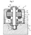
- Fig. 1 shows a sectional view of a motor-driven Unit 1 according to a first embodiment of the invention.
- the unit 1 comprises a motor unit 2, which in this embodiment is designed as an electric motor and a work machine 3 used in this embodiment is designed as a pump.
- the electric motor 2 has a cup-shaped open on at least one side Motor housing 4 with a base 5 facing the pump, while the pump 3 does not have a pump housing 6 with several bores shown, in which, inter alia, not shown Pump pistons are slidably arranged.
- the pump housing 6 can also not shown valves be provided, with the help of a control of caused by the pump 3 pressure medium flows become.
- a motor shaft is located within the motor housing 4 7 with a rotor 8, an armature 9 and windings 10 has.
- On the motor shaft 7 is near the bottom 5 a commutator 11 for supplying power to the windings 10 non-rotatably attached.
- At the bottom 5 there is also a brush holder 12 attached, the resilient in electrical connection with the commutator 11 standing brushes 13 in quivers leads.
- permanent magnets 14 are provided, the permanent magnetic fields interacting with those through the windings 10 generated magnetic fields drive the motor 2.
- the one that closes the open end of the cup-shaped motor housing Bottom 5 has a central through hole 15 through which one end of the motor shaft 7 into a blind hole-like recess 16 of the pump housing 6 protrudes.
- the not shown protrude transversely into the recess 16
- Pump piston which is rotatably connected to the motor shaft 7 connected pump eccentric 17 are applied.
- a receptacle 18 is provided which a first bearing 19 for Bearing of the end of the motor shaft 7 facing the pump 3 records.
- the diameter of this receptacle 18 is larger than the diameter of the remaining recess 16 in which the Pump eccentric 17 is added.
- the camp 19 is in the Recording 18 caulked, pressed or otherwise set such that it is non-positively radial to the motor shaft 7 is set.
- the motor shaft 7 is on her end facing away from the pump in a second bearing 20, that in a correspondingly shaped in the motor housing 4 Recording 21 is pressed.
- the second bearing 20 can be designed as a fixed bearing his.
- the second bearing 20 is, for example, as Ball bearings designed, which improves efficiency and the motor housing 4 in the area of the receptacle 21 of the second Bearing 20 can be shortened.
- the applicant reserves the right this subject of a second designed as a fixed bearing Bearing 20 in a motor-driven unit 1 also without the non-positive determination of the first bearing 19 independently to pursue.
- FIG. 2 shows a preferred embodiment of the pump eccentric 17.
- the pump eccentric 17 has two sections 22 and 23 offset in the longitudinal direction.
- the lower section 22 has a rotationally cylindrical outer shape which is arranged offset from the recess 16 by the eccentricity e 1 .
- the underside of the lower section 22 reaches as far as the bottom of the recess 16.
- the lower section 22 is integrally connected to the upper section 23 which forms the connection to the motor shaft 7 and which likewise has a rotationally cylindrical outer shape and an inner bore 24.
- the inner bore 24 provided in the upper section 14 is aligned when the motor shaft 7 is mounted with the central axis of the motor shaft 7 and is thus offset from the central axis of the lower section 22 by the eccentricity e 1 .
- the lower section 22 is almost its entire length surrounded by a roller bearing 25 with an outer ring 26.
- the roller bearing 25 has an encapsulated row of needles 27 as rolling elements.
- the outer ring 26 operated with his Circumferential surface that protrudes radially into the recess 16 Pump piston ends not shown.
- the pump eccentric 17 also has an unbalance compensation.
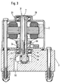
- Figures 3 to 5 show preferred types of attachment of the motor shaft 7 on an inner ring 28 of the first bearing 19, so the first bearing 19 can serve as a fixed bearing.
- the motor shaft 7 and the inner ring 28 of the first Warehouse 19 already very precisely manufactured components, see above that the game between these two components is extremely low is.
- the radial freedom of movement of the motor shaft 7 results from the outer diameter of the motor shaft 7 and the inner diameter of the inner ring 28. That is enough an adhesive connection (possibly using a known Gluing technology for gluing steel on steel) between Motor shaft 7 and inner ring 28 to the motor shaft 7 on the first Define camp 19.
- the first bearing 19 takes over the fixed bearing function again. Toward both the first 19 and the second Bearing 20 designed as a fixed bearing, there is one for the noise behavior favorable bracing of the two bearings 19 and 20 to each other.
- Fig. 3 shows a first type of attachment of the motor shaft 7 on Inner ring 28.
- the motor shaft 7 is a hollow shaft educated.
- the hollow shaft is replaced by the Inner ring 28 of the first bearing 19 and completely over the pushed upper section 23 of the pump eccentric 17 until it at a stop provided on the upper section 23 29 triggers.
- the motor shaft 7 in the amount of Inner ring 28 by a suitable method or means spread on.
- the upper section 23 is spread open whose outside diameter is equal to the inside diameter corresponds to the motor shaft 7. With the expansion of the top Section 23 thus also expands the motor shaft 7 and there is a frictional connection between the top Section 23, motor shaft 7 and inner ring 28.
- the upper section 23 of the pump eccentric 17 has a height which in essentially corresponds to the height of the inner ring 28. In order to it is ensured that when the upper section is expanded 23 in the radial direction to the motor shaft 7 on the inner ring 28 acting adhesion across the entire inner surface of the Inner ring 28 acts.
- the first bearing 19 can also be arranged in the pump housing in this way be that the motor shaft 7 still down from the protrudes first bearing 19 and at a distance from the first bearing 19 Place on the pump eccentric 17 rotatably attached is. Then the motor shaft 7 at the level of the first bearing 19 expanded by another suitable means to the To achieve adhesion with the inner ring 28. For example there may be a conical section within the motor shaft 7 be provided at the level of the first bearing 19, in the one corresponding counterpart for expanding the motor shaft 7 can be pushed in.
- Mounting opening 31 For screwing the screw 30 into the inner bore 24 is centrally in the receptacle 21 for the second bearing 20 one Mounting opening 31 is provided in the motor housing 4.
- This Mounting opening 31 can be a suitable screwing device the motor shaft 7 are inserted so that the screw 30th with the motor shaft 7 held down in the inner bore 24 can be screwed in.
- the opening diameter of the mounting opening 31 is dimensioned so that during screwing from the outside of the motor housing 4 yet another Tool for holding down the motor shaft 7 on the end face the hollow shaft can be applied.
- the rotating cylindrical outer surface of the upper section 23 can also be conical that the hollow motor shaft 7 when being pulled onto the upper section 23 is expanded. This is also done by the mounting opening 31 a screw 30 in the inner bore 24 screwed in that the motor shaft 7 over the upper Section 23 is pulled.
- a Washer not shown, the outer diameter corresponds to the outer diameter of the motor shaft 7, placed on the top face and one through the washer protruding screw 30 of corresponding length in the Inner bore 24 are screwed.
- Drain channel 32 a not shown pin for support of the assembly torque so inserted into the recess 16 be that the pump eccentric 17 when screwing in respective screw 30 is prevented from rotating.
- the motor shaft 7 on the inner ring 28 can the assembly opening 31 by a cover, not shown, for sealing the motor housing 4 are closed.
- a cover not shown, for sealing the motor housing 4 are closed.
- the opening in the front the hollow motor shaft 7 sealed by a suitable cover become.
- FIG. 4 shows a third type of fastening of the motor shaft 7 on the inner ring 28.
- the inner bore 24 of the pump eccentric 17 becomes a ball 33 or an unillustrated light tapered eccentric piece pressed in such a way that the upper section 23 of the pump eccentric 17 expanded becomes.
- the ball 33 is dimensioned so that its outer diameter slightly larger than the inner diameter of the inner bore 24 is. This in turn becomes the one you want Adhesion between upper section 23, lower end of the Motor shaft 7 and inner ring 28 of the first bearing 19 achieved. So when you press the ball 33 or the eccentric piece the pump eccentric 17 does not come down from the motor shaft 7 is pressed, there is a further mounting opening 34 in the pump housing 6 formed substantially with the central axis of the upper section 23 of the pump eccentric 17 flees. Through this mounting opening 34 can from below Support pin to hold against the pump eccentric 17 be introduced.
- the motor shaft 7 can be a hollow shaft with a larger outside diameter than the inside diameter of the inner ring 28 may be formed, with the lower End of the motor shaft 17 is a shoulder 35 with an outer diameter equal to the inner diameter of the inner ring 28 provided is.
- This approach 35 can be integral with the motor shaft 7 be formed.
- the upper section 23 of the pump eccentric 17 now has a lower height than the height of the inner ring 28 so that it with the motor shaft pushed on 7 only partially from below into the inner ring 28 immersed.
- the motor shaft 7 is in the inner ring 28 pushed that between neck 35 and lower end the motor shaft 7 formed stop at the top of the inner ring 28 strikes. Then one in FIG. 5 screw, not shown, from above through the hollow motor shaft 7 in the inner bore provided with an internal thread 24 screwed in. The screw head can do this either inside the motor shaft 7 at the stop Support to approach 35 or at the top of the top Motor shaft 7.
- the inner ring 28 in the axial direction of the motor shaft 7 between the pump eccentric 17 and the motor shaft 7 frictionally clamped, whereby these components are thus made free of play.
- a pin can be screwed in from below Drain channel 32 are inserted to rotate the pump eccentric 17 lock.
- the motor shaft 7 can also be solid, with 35 at its lower neck centrally another with an external thread Screw extension 36 is integrally connected.
- the motor shaft 7 will be installed directly on its upper one End rotated, whereby the screw extension 36 in the an internal bore 24 provided with a corresponding internal thread is screwed in and the axial tension between Motor shaft 7, inner ring 28 and pump eccentric 17 brings about.
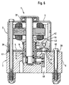
- Fig. 6 shows an alternative to Fig. 1 non-positive Determination of the first bearing 19 according to a second preferred Embodiment of the invention.
- the first camp 19 is in the bottom 5 designed as a metal plate of the motor housing 4 is pressed.
- the floor 5 points its through opening 15 an axially down into the Recess 16 projecting cylindrical projection 37, which is integrally connected to the bottom 5.
- the outside diameter the projection 37 corresponds to the input side Inner diameter of the recess 16 so that on the one hand a kind of assembly aid when assembling the electric motor 2 and pump 3 and on the other hand a stabilization the projection 37 is created in the radial direction.
- the height the projection 37 corresponds essentially to the height of the first bearing 19. This can be an inexpensive needle bearing be trained.
- the second bearing 20 is Fixed camp trained.
- the bottom 5 has an axially flanged axially upward on its circumference Apron 38, which is used to lock the motor housing 4 from below into the cup-shaped motor housing 4 is pressed in non-positively.
- the motor housing 4 has in turn one radially outward in its opening area flared apron 39 on.
- the apron 39 of the engine case 4 is by means of appropriate screws 40 to the Pump housing 6 screwed.
- Ring seal 41 can be placed. This ring seal 41 seals the recess 16 and thus the interior of the pump 3 to the outside. This sealing function has in the previous Embodiments that are pressed into the pump housing 6 first bearing 19 taken over.
- a pad 42 attached, which the brush holder 12 together with brushes 13 and a connector 43 carries.
- the connector 43 is electrical on the pad with the Brushes 13 connected and can be used as a simple plug connection be trained.
- the connector 43 a socket 44 with a connector spring provided therein 45 on, in which a suitably shaped not shown connector can be resiliently received.
- a through opening 46 in the connecting surface 42 in the bottom 5 one of the through opening 46 opposite Through opening 47, and one through the pump housing 6 extending and down from the pump housing 6 free through opening 48 formed, wherein the latter through opening 48 is opposite to the through opening 47.
- the connector 43 opens axially downwards through the three aligned Through openings 46, 47 and 48. The not shown The connector can thus be seen from below when the unit 1 is fully assembled through the pump housing 6 with the electric motor 2 electrically get connected.
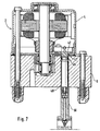
- the connector 43 can be inside the motor housing 4th may be provided, but instead, as in FIG. 7 shown, one through the through opening 47 the bottom 5 protruding adapter 49 (e.g. a simple plug) be provided on the connecting surface 42 (in one piece connected to the pad 42, which thus at their Contact surfaces to the motor housing 4 be electrically insulated must, or electrically opposite the pad 42nd isolated and formed as a separate component). In the latter case, a corresponding plug socket 50 from below through the through hole 48 of the pump housing 6 pushed onto the adapter 49. So in both cases an electrical connection to an electronic control unit of the electric motor 2 are manufactured.
- the adapter 43 or 49 can be separately or to a not shown Electronics box to be proper.
- Fig. 8 shows an alternative to Figures 1 and 6 non-positive Determination of the first bearing 19 according to one third preferred embodiment of the invention.
- the bottom 5 formed as a metal sign
- Motor housing 4 already the outer bearing sleeve 51 as Needle bearing designed first bearing 19.
- the radial direction acting adhesion of the first bearing 19 is by pressing the needles 52 and the motor shaft 7 into the Bearing sleeve 51 achieved.
- This embodiment is advantageous saved one component.
- the pump housing is axially at least one in the bottom 5 Punch 54 projecting into a recess 53 at the bottom.
- the recess 53 is arranged at the entrance of the recess 16 and has a larger diameter than the recess 16 on.
- Figure 9 is a simplified exploded view to explain the individual assembly steps during production of the unit 1 according to an embodiment with a trained as a floating bearing 19 or one with the motor shaft glued first bearing 19.
- the roller bearing 25 of the pump eccentric 17 is together with a dome ring, not shown, in the Recess 16 inserted and mounted there.
- the first bearing 19 in the pump housing 6 becomes non-positive fixed by caulking there, pressed in or otherwise determined non-positively.
- the third step is the one with the motor shaft already assembled 7 provided electric motor 2 on the pump housing 6 mounted (e.g. by screwing). The motor shaft 7 pushed through the inner ring 28.
- the motor shaft 7 can be coated with an adhesive so that the motor shaft 7 after curing of the adhesive in the inner ring 28 of the first bearing 19 is set.
- the first camp 19 works then as a fixed bearing
- the second bearing 20 both can be designed as a loose as well as a fixed bearing.
- the Motor shaft 7 already has one piece at its lower end one together with the roller bearing 25 as a pump eccentric 17 acting radially offset approach 55. This approach 55 is through the inner ring 28 and the roller bearing 25 so far pushed until a stop 56 on the top of the housing Outer ring 26 of the roller bearing 25 strikes.
Landscapes
- Engineering & Computer Science (AREA)
- Mechanical Engineering (AREA)
- Physics & Mathematics (AREA)
- General Engineering & Computer Science (AREA)
- Power Engineering (AREA)
- Fluid Mechanics (AREA)
- Transportation (AREA)
- Electromagnetism (AREA)
- Connection Of Motors, Electrical Generators, Mechanical Devices, And The Like (AREA)
- Harvester Elements (AREA)
Applications Claiming Priority (2)
| Application Number | Priority Date | Filing Date | Title |
|---|---|---|---|
| DE19914258 | 1999-03-29 | ||
| DE19914258A DE19914258A1 (de) | 1999-03-29 | 1999-03-29 | Motorangetriebenes Aggregat |
Publications (2)
| Publication Number | Publication Date |
|---|---|
| EP1041700A2 true EP1041700A2 (fr) | 2000-10-04 |
| EP1041700A3 EP1041700A3 (fr) | 2003-10-08 |
Family
ID=7902844
Family Applications (1)
| Application Number | Title | Priority Date | Filing Date |
|---|---|---|---|
| EP00105269A Ceased EP1041700A3 (fr) | 1999-03-29 | 2000-03-14 | Organe entrainé par moteur |
Country Status (2)
| Country | Link |
|---|---|
| EP (1) | EP1041700A3 (fr) |
| DE (1) | DE19914258A1 (fr) |
Cited By (7)
| Publication number | Priority date | Publication date | Assignee | Title |
|---|---|---|---|---|
| WO2006067070A1 (fr) * | 2004-12-21 | 2006-06-29 | Continental Teves Ag & Co. Ohg | Dispositif de regulation de pression electrohydraulique pour systemes de freinage de vehicules a moteur |
| WO2007060066A1 (fr) * | 2005-11-24 | 2007-05-31 | Continental Automotive Gmbh | Groupe moteur-pompe a etancheite amelioree |
| EP1746288A3 (fr) * | 2002-11-11 | 2009-03-04 | Continental Teves AG & Co. oHG | Ensemble moteur-pompe |
| WO2008116442A3 (fr) * | 2007-03-23 | 2009-03-12 | Schaeffler Kg | Palier doté d'un moyen adhésif intégré aux fins de fixation dans un boîtier ou sur un arbre |
| DE102011087083A1 (de) * | 2011-11-25 | 2013-05-29 | Robert Bosch Gmbh | Elektromotor |
| EP2546117A3 (fr) * | 2011-07-11 | 2015-02-25 | Nissin Kogyo Co., Ltd. | Pompe à moteur |
| EP3754816A4 (fr) * | 2018-02-15 | 2021-03-24 | Panasonic Intellectual Property Management Co., Ltd. | Moteur et dispositif électrique le comportant |
Families Citing this family (1)
| Publication number | Priority date | Publication date | Assignee | Title |
|---|---|---|---|---|
| JP7259643B2 (ja) | 2019-08-27 | 2023-04-18 | 株式会社デンソーダイシン | 絞り弁装置及び絞り弁装置の製造方法 |
Family Cites Families (9)
| Publication number | Priority date | Publication date | Assignee | Title |
|---|---|---|---|---|
| US4676672A (en) * | 1985-02-19 | 1987-06-30 | International Business Machines Corporation | Precision spindle |
| DE4430909A1 (de) * | 1994-08-31 | 1996-03-07 | Bosch Gmbh Robert | Einheit aus Antriebsmotor und Radialkolbenpumpe |
| DE4433970A1 (de) * | 1994-09-23 | 1996-03-28 | Teves Gmbh Alfred | Elektromotor für ein Triebwerk, insbesondere für eine Pumpe |
| DE4433972A1 (de) * | 1994-09-23 | 1996-03-28 | Teves Gmbh Alfred | Elektromotor, Pumpe sowie ein Elektromotor/Pumpenaggregat |
| DE19615053A1 (de) * | 1996-04-17 | 1997-10-23 | Teves Gmbh Alfred | Elektromotor-/Pumpenaggregat |
| JPH1075547A (ja) * | 1996-06-28 | 1998-03-17 | Mitsuba Corp | ピストンポンプおよびピストンポンプ駆動用の電動モータの組付け方法 |
| DE19653638A1 (de) * | 1996-12-20 | 1998-06-25 | Teves Gmbh Alfred | Elektromotor-Pumpenaggregat |
| DE19805003B4 (de) * | 1998-02-07 | 2006-09-28 | Robert Bosch Gmbh | Elektromotor |
| DE19813301A1 (de) * | 1998-03-26 | 1999-09-30 | Bosch Gmbh Robert | Pumpeneinheit |
-
1999
- 1999-03-29 DE DE19914258A patent/DE19914258A1/de not_active Withdrawn
-
2000
- 2000-03-14 EP EP00105269A patent/EP1041700A3/fr not_active Ceased
Cited By (10)
| Publication number | Priority date | Publication date | Assignee | Title |
|---|---|---|---|---|
| EP1746288A3 (fr) * | 2002-11-11 | 2009-03-04 | Continental Teves AG & Co. oHG | Ensemble moteur-pompe |
| WO2006067070A1 (fr) * | 2004-12-21 | 2006-06-29 | Continental Teves Ag & Co. Ohg | Dispositif de regulation de pression electrohydraulique pour systemes de freinage de vehicules a moteur |
| WO2007060066A1 (fr) * | 2005-11-24 | 2007-05-31 | Continental Automotive Gmbh | Groupe moteur-pompe a etancheite amelioree |
| CN101385220B (zh) * | 2005-11-24 | 2011-08-24 | 欧陆汽车有限责任公司 | 具有改进的密封件的马达-泵-总成 |
| WO2008116442A3 (fr) * | 2007-03-23 | 2009-03-12 | Schaeffler Kg | Palier doté d'un moyen adhésif intégré aux fins de fixation dans un boîtier ou sur un arbre |
| EP2546117A3 (fr) * | 2011-07-11 | 2015-02-25 | Nissin Kogyo Co., Ltd. | Pompe à moteur |
| US9821782B2 (en) | 2011-07-11 | 2017-11-21 | Nissin Kogyo Co., Ltd. | Motor pump |
| DE102011087083A1 (de) * | 2011-11-25 | 2013-05-29 | Robert Bosch Gmbh | Elektromotor |
| US9140256B2 (en) | 2011-11-25 | 2015-09-22 | Robert Bosch Gmbh | Electric motor |
| EP3754816A4 (fr) * | 2018-02-15 | 2021-03-24 | Panasonic Intellectual Property Management Co., Ltd. | Moteur et dispositif électrique le comportant |
Also Published As
| Publication number | Publication date |
|---|---|
| DE19914258A1 (de) | 2000-10-05 |
| EP1041700A3 (fr) | 2003-10-08 |
Similar Documents
| Publication | Publication Date | Title |
|---|---|---|
| DE60023782T2 (de) | Kleinstmotor und sein Herstellungsverfahren | |
| DE4315826C5 (de) | Motor-Pumpen-Aggregat | |
| DE102008058433A1 (de) | Bürstenloser Motor und Herstellungsverfahren desselben | |
| EP0698183A1 (fr) | Ensemble pompe et moteur electrique | |
| EP0988200A1 (fr) | Organe hydraulique | |
| DE19727231A1 (de) | Kolbenpumpe und Zusammenbauverfahren für einen Elektromotor zum Antreiben der Kolbenpumpe | |
| DE102014218034A1 (de) | Positionierung eines umspritzten Stators für einen Kupplungsaktor oder einen Getriebeaktor und Einbringen eines Rotorlagemagneten in einen solchen Aktor | |
| EP1745540B1 (fr) | Moteur electrique et unite d'entrainement de transmission destines a des actionneurs dans un vehicule | |
| DE19642133A1 (de) | Motor-Pumpen-Einrichtung | |
| EP1041700A2 (fr) | Organe entrainé par moteur | |
| EP0797733B1 (fr) | Pompe a piston | |
| DE19709777A1 (de) | Motor-Pumpenaggregat | |
| DE69207625T2 (de) | Hermetische Motor-Verdichter-Einheit mit verbessertem Motortragegestell oder -Stützträger | |
| EP0853727B1 (fr) | Ensemble pompe et moteur electrique | |
| DE19602173A1 (de) | Elektromotorgehäuse | |
| DE2230527A1 (de) | Geblaese mit einem elektromotor und einem von diesem angetriebenen luefterrad | |
| EP0894359A1 (fr) | Ensemble moteur electrique-pompe | |
| DE102020204831A1 (de) | Elektronisch kommutierte Maschine, elektronisch schlupfregelbare Bremsanlage und Verfahren zur Herstellung einer elektronisch kommutierten Maschine | |
| EP1372248A2 (fr) | Méthode d'assemblage de moteur avec chemise d'entrefer | |
| DE20211064U1 (de) | Hydrodynamisches Drucklager | |
| DE3311557A1 (de) | Verfahren zur montage eines elektromotors sowie elektromotor | |
| DE19809571C1 (de) | Motorantrieb, insbesondere Motor-Pumpen-Antrieb für eine Kraftfahrzeug-Antiblockier-Bremsvorrichtung | |
| DE19633169A1 (de) | Elektromotor-/Pumpenaggregat | |
| DE2059017A1 (de) | Elektromotor geringer Leistung | |
| DE102006005604B4 (de) | Fluiddynamisches Lagersystem |
Legal Events
| Date | Code | Title | Description |
|---|---|---|---|
| PUAI | Public reference made under article 153(3) epc to a published international application that has entered the european phase |
Free format text: ORIGINAL CODE: 0009012 |
|
| AK | Designated contracting states |
Kind code of ref document: A2 Designated state(s): AT BE CH CY DE DK ES FI FR GB GR IE IT LI LU MC NL PT SE |
|
| AX | Request for extension of the european patent |
Free format text: AL;LT;LV;MK;RO;SI |
|
| RIC1 | Information provided on ipc code assigned before grant |
Ipc: 7F 16C 35/063 B Ipc: 7H 02K 7/075 B Ipc: 7H 02K 5/173 B Ipc: 7H 02K 7/08 A |
|
| PUAL | Search report despatched |
Free format text: ORIGINAL CODE: 0009013 |
|
| AK | Designated contracting states |
Kind code of ref document: A3 Designated state(s): AT BE CH CY DE DK ES FI FR GB GR IE IT LI LU MC NL PT SE |
|
| AX | Request for extension of the european patent |
Extension state: AL LT LV MK RO SI |
|
| 17P | Request for examination filed |
Effective date: 20040408 |
|
| AKX | Designation fees paid |
Designated state(s): DE FR GB |
|
| 17Q | First examination report despatched |
Effective date: 20040728 |
|
| 17Q | First examination report despatched |
Effective date: 20040728 |
|
| STAA | Information on the status of an ep patent application or granted ep patent |
Free format text: STATUS: THE APPLICATION HAS BEEN REFUSED |
|
| 18R | Application refused |
Effective date: 20060814 |