EP1041766A2 - Anordnung zur Übertragung von vielfachen digitalen Darstellungen eines Signals - Google Patents
Anordnung zur Übertragung von vielfachen digitalen Darstellungen eines Signals Download PDFInfo
- Publication number
- EP1041766A2 EP1041766A2 EP00302319A EP00302319A EP1041766A2 EP 1041766 A2 EP1041766 A2 EP 1041766A2 EP 00302319 A EP00302319 A EP 00302319A EP 00302319 A EP00302319 A EP 00302319A EP 1041766 A2 EP1041766 A2 EP 1041766A2
- Authority
- EP
- European Patent Office
- Prior art keywords
- signal
- representation
- frequency bands
- representations
- stream
- Prior art date
- Legal status (The legal status is an assumption and is not a legal conclusion. Google has not performed a legal analysis and makes no representation as to the accuracy of the status listed.)
- Withdrawn
Links
- 238000000034 method Methods 0.000 claims description 63
- 238000012937 correction Methods 0.000 claims description 13
- 238000001514 detection method Methods 0.000 claims description 7
- 238000011084 recovery Methods 0.000 claims description 3
- 230000005236 sound signal Effects 0.000 abstract description 37
- 238000004891 communication Methods 0.000 abstract description 18
- 230000005540 biological transmission Effects 0.000 abstract description 11
- 238000002156 mixing Methods 0.000 description 20
- 230000000295 complement effect Effects 0.000 description 19
- 239000000969 carrier Substances 0.000 description 12
- 238000013459 approach Methods 0.000 description 11
- 238000013139 quantization Methods 0.000 description 11
- 238000007493 shaping process Methods 0.000 description 9
- 230000008569 process Effects 0.000 description 7
- 238000010586 diagram Methods 0.000 description 5
- 230000004044 response Effects 0.000 description 5
- 238000013461 design Methods 0.000 description 4
- 230000002411 adverse Effects 0.000 description 3
- 238000007906 compression Methods 0.000 description 3
- 239000000284 extract Substances 0.000 description 3
- 238000012549 training Methods 0.000 description 3
- 230000008901 benefit Effects 0.000 description 2
- 230000015556 catabolic process Effects 0.000 description 2
- 230000006835 compression Effects 0.000 description 2
- 238000006731 degradation reaction Methods 0.000 description 2
- 230000009977 dual effect Effects 0.000 description 2
- 230000002708 enhancing effect Effects 0.000 description 2
- 230000014509 gene expression Effects 0.000 description 2
- 238000005192 partition Methods 0.000 description 2
- 238000000926 separation method Methods 0.000 description 2
- 230000011664 signaling Effects 0.000 description 2
- 238000001228 spectrum Methods 0.000 description 2
- 238000007476 Maximum Likelihood Methods 0.000 description 1
- 230000003044 adaptive effect Effects 0.000 description 1
- 239000000654 additive Substances 0.000 description 1
- 230000000996 additive effect Effects 0.000 description 1
- 125000004122 cyclic group Chemical group 0.000 description 1
- 230000006735 deficit Effects 0.000 description 1
- 238000005516 engineering process Methods 0.000 description 1
- 239000002360 explosive Substances 0.000 description 1
- 230000036039 immunity Effects 0.000 description 1
- 230000006872 improvement Effects 0.000 description 1
- 230000002452 interceptive effect Effects 0.000 description 1
- 239000011159 matrix material Substances 0.000 description 1
- 239000000203 mixture Substances 0.000 description 1
- 230000000737 periodic effect Effects 0.000 description 1
- 230000000246 remedial effect Effects 0.000 description 1
- 238000009877 rendering Methods 0.000 description 1
- 230000035945 sensitivity Effects 0.000 description 1
- 238000000638 solvent extraction Methods 0.000 description 1
- 230000003595 spectral effect Effects 0.000 description 1
- 230000035899 viability Effects 0.000 description 1
Images


Classifications
-
- H—ELECTRICITY
- H04—ELECTRIC COMMUNICATION TECHNIQUE
- H04H—BROADCAST COMMUNICATION
- H04H20/00—Arrangements for broadcast or for distribution combined with broadcast
- H04H20/28—Arrangements for simultaneous broadcast of plural pieces of information
- H04H20/30—Arrangements for simultaneous broadcast of plural pieces of information by a single channel
-
- H—ELECTRICITY
- H04—ELECTRIC COMMUNICATION TECHNIQUE
- H04H—BROADCAST COMMUNICATION
- H04H60/00—Arrangements for broadcast applications with a direct linking to broadcast information or broadcast space-time; Broadcast-related systems
- H04H60/02—Arrangements for generating broadcast information; Arrangements for generating broadcast-related information with a direct linking to broadcast information or to broadcast space-time; Arrangements for simultaneous generation of broadcast information and broadcast-related information
- H04H60/07—Arrangements for generating broadcast information; Arrangements for generating broadcast-related information with a direct linking to broadcast information or to broadcast space-time; Arrangements for simultaneous generation of broadcast information and broadcast-related information characterised by processes or methods for the generation
-
- H—ELECTRICITY
- H04—ELECTRIC COMMUNICATION TECHNIQUE
- H04H—BROADCAST COMMUNICATION
- H04H2201/00—Aspects of broadcast communication
- H04H2201/10—Aspects of broadcast communication characterised by the type of broadcast system
- H04H2201/18—Aspects of broadcast communication characterised by the type of broadcast system in band on channel [IBOC]
- H04H2201/186—AM digital or hybrid
Definitions
- the invention relates to systems and methods for communications of digitally modulated signals, and more particularly to systems and methods utilizing multiple bands including, e.g., parts of an amplitude-modulation (AM) frequency band, to communicate digitally modulated signals.
- multiple bands including, e.g., parts of an amplitude-modulation (AM) frequency band, to communicate digitally modulated signals.
- AM amplitude-modulation
- a perceptual audio coding (PAC) technique For example, to efficiently utilize bandwidth to communicate digital audio information, a perceptual audio coding (PAC) technique has been developed.
- PAC perceptual audio coding
- U.S. Patent No. 5,285,498 issued February 8, 1994 to Johnston and U.S. Patent No. 5,040,217 issued August 13, 1991 to Brandenburg et al., both of which are hereby incorporated by reference.
- each of a succession of time domain blocks of an audio signal representing audio information is coded in the frequency domain.
- each block is divided into coder bands, each of which is individually coded, based on psycho-acoustic criteria, in such a way that the audio information is significantly compressed, thereby requiring a smaller number of bits to represent the audio information than would be the case if the audio information were represented in a more simplistic digital format, such as the PCM format.
- AM radio broadcast adjacent geographic areas covered by AM radio broadcast are assigned different AM carrier frequencies, which are at least 20 kHz apart. Specifically, when they are exactly 20 kHz apart, the AM carrier assigned to the adjacent area is referred to as a "second adjacent carrier.” Similarly, when they are 10 kHz apart, the AM carrier assigned to the adjacent area is referred to as a "first adjacent carrier.”
- IBOC-AM in-band on channel AM
- hybrid IBOC-AM also known as “hybrid IBOC-AM”
- digitally modulated signals representing the audio information populate, e.g., a 30 kHz digital band centered at an analog host AM carrier.
- the power levels of the spectrums of the digitally modulated signals are allowed to be equally high across a 10 kHz subband in the digital band on each end thereof.
- second adjacent channel interference the dominant interfering carrier in this instance consists of a second adjacent carrier.
- the second adjacent channel interference degrades the digital communications in each of the adjacent areas, especially in the parts of the areas which are close to their common border.
- multistream coding in communicating a signal over multiple frequency bands including, e.g., in parts of the AM frequency band, multistream coding is implemented, whereby multiple digital representations each containing information descriptive of the signal are generated.
- the information contained in at least one of the representations is different than that contained in every other representation.
- at least one of the representations (referred to as a "core representation") contains core information, and the remaining non-core representations (referred to as “enhancement representations”) contain enhancement information.
- the core information is more generally descriptive of the signal than the enhancement information.
- the aforementioned signal may be recovered using all of the digital representations or a subset thereof if some of the frequency bands are severely affected by, e.g., the first or second adjacent channel interference caused by the first or second adjacent channel carrier described above in the case of the IBOC-AM system.
- the quality of the recovered signal varies with the actual representations used.
- the signal recovered using only the core representation has the minimal acceptable digital quality.
- the signal recovered using the enhancement representations, in addition to the core representation has relatively high quality. In the latter case, the more enhancement representations are used, the higher the quality. However, without the core representation, no signal of acceptable digital quality can be recovered.
- the frequency band which is the least susceptible to the interference is assigned to the core representation for transmission to improve the chance of recovery of a signal having at least acceptable digital quality.
- an IBOC-AM system implementing the multistream transmission scheme described above affords increased robustness against adverse channel conditions, and more graceful degradation of digital communications when such conditions occur.
- the invention is directed to a technique for digital communications over multiple frequency bands including, e.g., parts of an amplitude-modulation (AM) frequency band which is currently used by radio stations for AM radio broadcast.
- AM amplitude-modulation
- FIG. 1 in a prior art in-band on channel AM (IBOC-AM) (also known as “hybrid IBOC-AM”) scheme which has been proposed, digitally modulated signals representative of digital audio information populate digital band 101 which is 30 kHz wide, and centered at an analog host AM carrier having a frequency f c for radio broadcast.
- An analog AM signal containing the radio broadcast although not shown in Fig. 1, occupies a subband ranging from f c - 5 kHz to f c + 5 kHz.
- a multicarrier modem is used to transmit the digitally modulated signals, with uniform transmission power allocated thereto, resulting in power profile 103 of the signal spectrums which is uniform across digital band 101 and symmetric about f c .
- the digital transmission by the multicarrier modem may be in accordance with an orthogonal frequency division multiplexed (OFDM) (also known as a "discrete multi-tone”) scheme.
- OFDM orthogonal frequency division multiplexed
- Fig. 2 illustrates transmitter 201 in an IBOC-AM communications system embodying the principles of the invention.
- the system is used to effectively communicate digitally modulated signals representing, e.g., audio information, over an AM frequency band in a geographic area which is assigned an analog host AM carrier whose frequency is f c , despite any adjacent channel interference affecting the digitally modulated signals.
- multistream coding is implemented in the IBOC-AM system to generate multiple bit streams representing an audio signal containing the audio information, and the bit streams are respectively transmitted through individual subbands within digital band 101.
- the audio signal may be recovered using all of the bit streams received or a subset thereof if some of the subbands are severely affected by the adjacent channel interference and/or other adverse channel conditions.
- the audio quality e.g., based on a signal-to-noise ratio (SNR) or preferably perceptually based measure, of the recovered signal varies with the underlying, received bit streams used. In general, the more received bit streams are used, the higher the audio quality of the recovered signal.
- SNR signal-to-noise ratio
- the inventive system affords increased robustness against adverse channel conditions, and more graceful degradation of digital communications when such conditions occur.
- three bit streams are used to communicate an audio signal containing audio information in accordance with the invention, one of the bit streams represents core audio information and is referred to as a "C-stream.”
- the other two bit streams represent first and second enhancement audio information, and are referred to as "E 1 -stream” and "E 2 -stream,” respectively.
- E 1 -stream first and second enhancement audio information
- E 2 -stream second enhancement audio information
- the audio signal recovered based on the C-stream alone although viable, has the minimum acceptable quality
- the audio signal recovered based on the C-stream in combination with either E 1 -stream or E 2 -stream has relatively high quality
- the audio signal recovered based on the C-stream in combination with both E 1 -stream and E 2 -stream has the highest quality.
- any audio signal recovered based only on the E 1 -stream and/or E 2 -stream is not viable.
- the C-stream representing the minimal core audio information is transmitted through subband 303 in Fig. 3 between f c - 5 kHz and f c + 5 kHz which is immune to second adjacent channel interference;
- the E 1 -stream representing first enhancement audio information is transmitted through subband 305 between f c - 15 kHz and f c - 5 kHz which is subject to second adjacent channel interference;
- the E 2 -stream representing second enhancement audio information is transmitted through subband 307 between f c + 5 kHz and f c + 15 kHz which is also subject to second adjacent channel interference.
- the minimal core audio information would be recoverable despite any second adjacent channel interference, and enhanced by any of E 1 -stream and E 2 -stream depending on whether the respective subbands 305 and 307 are severely affected by the second adjacent channel interference.
- an analog audio signal a(t) containing audio information to be transmitted by transmitter 201 is fed to embedded audio coder 203 which is fully described below. It suffices to know for now that coder 203 based on the multistream coding generates the aforementioned C-stream, E 1 -stream and E 2 -stream representing the analog signal on leads 209a, 209b and 209c, respectively.
- the bit rates for the C-stream, E 1 -stream and E 2 -stream, thus generated, are M kb/sec, S1 kb/sec and S2 kb/sec, respectively.
- M, S1 and S2 in that case may be set to be 16, 16 and 16, respectively.
- These bit rates are selected such that if all of the streams are successfully received, the quality of the resulting recovered signal is close to that of a single stream generated by a conventional non-embedded audio coder at M + S1 + S2 kb/sec .
- the quality of the resulting signal recovered based on a combination of the C-stream with the E 1 -stream or E 2 -stream is close to that of a single stream generated by the conventional non-embedded audio coder at M + S1 kb/sec or M + S2 kb/sec.
- the resulting quality corresponding to the combination of the C-stream with the E 1 -stream or E 2 -stream is significantly higher than the analog AM quality.
- Outer channel coder 215a encodes the C-stream according to a well known forward error correction coding technique, e.g., the Reed Solomon coding technique in this instance, or alternatively a cyclic redundancy check (CRC) binary block coding technique, to afford correction and/or detection of errors in the C-stream after its transmission.
- the C-stream is processed by coder 215a on a block by block basis, with each block having a predetermined number of bits.
- coder 215a appends the Reed Solomon check symbols resulting from the encoding to each corresponding block.
- coders 215b and 215c respectively processes the E 1 -stream and E 2 -stream on a block by block basis, and append Reed Solomon check symbols to each corresponding block of the streams for error correction and/or detection purposes.
- Reed Solomon coded C-stream, Reed Solomon coded E 1 -stream and Reed Solomon coded E 2 -stream are fed to trellis coders 221a, 221b and 221c, respectively.
- Trellis coder 221a processes the received Reed Solomon coded C-stream on a symbol (different from a Reed Solomon check symbol) interval by symbol interval basis, where the symbol interval has a predetermined duration T 1 .
- coder 221a encodes the received bit stream in accordance with a trellis code to provide the communications system with a so-called "coding gain" which manifests itself in the form of enhance immunity to such random channel impairments as additive noise, without sacrificing the source bit rate or additional broadcast bandwidth.
- coder 221a introduces redundancy into the received bit stream in accordance with the trellis code to allow use of a maximum likelihood decoding technique at receiver 503 in Fig. 5 to be described. This redundancy takes the form of one or more additional bits.
- coder 221a forms an encoded word, which includes redundancy bits and bits from the received Reed Solomon coded C-stream and is used to select a symbol from a signal constellation of conventional design.
- the selected symbols from coder 221a are interleaved by interleaver 227a to pseudo-randomize the symbols.
- multicarrier modem 230a processes K 1 symbols from interleaver 227a in accordance with the well known OFDM scheme, where K 1 is a predetermined number. In a well known manner, modem 230a generates K 1 pulse shaping carriers or digitally modulated signals corresponding to the K 1 symbols.
- Transmit circuit 235a may include, e.g., a radio-frequency (RF) up-converter, a power amplifier and an antenna, all of conventional design.
- RF radio-frequency
- trellis coder 221b forms an encoded word, which includes redundancy bits and bits from the received Reed Solomon coded E 1 -stream and is used to select a symbol from a second predetermined signal constellation, where T 2 represents a predetermined duration.
- the resulting sequence of selected symbols are interleaved by interleaver 227b to pseudo-randomize the symbols.
- multicarrier modem 230b processes K 2 symbols from interleaver 227b in accordance with the well known OFDM scheme, where K 2 is a predetermined number.
- modem 230b generates K 2 pulse shaping carriers or digitally modulated signals corresponding to the K 2 symbols.
- the resulting pulse shaping carriers are transmitted by transmit circuit 235b through subband 305 with power profile 311.
- trellis coder 221c similarly forms an encoded word, which includes redundancy bits and bits from the received Reed Solomon coded E 2 -stream and is used to select a symbol from a third predetermined signal constellation, where T 3 represents a predetermined duration.
- the resulting sequence of selected symbols are interleaved by interleaver 227c to pseudo-randomize the symbols.
- multicarrier modem 230c transmits K 3 symbols from interleaver 227b in accordance with the well known OFDM scheme, where K 3 is a predetermined number.
- modem 230b generates K 3 pulse shaping carriers or digitally modulated signals corresponding to the K 3 symbols.
- Embedded audio coder 203 performing the aforementioned multistream coding on the input audio signal a(t) will now be described.
- analog-to-digital (A/D) convertor 405 in coder 203 digitizes a(t) in a conventional manner, providing PCM samples of a(t). These PCM samples are fed to both filterbank 409 and perceptual model processor 411.
- Filterbank 409 divides the samples into time domain blocks, and performs a modified discrete cosine transform (MDCT) on each block to provide a frequency domain representation therefor.
- MDCT modified discrete cosine transform
- Such a frequency domain representation is bandlimited by low-pass filter (LPF) 413 to the 0 to 6 kHz frequency range in this instance.
- LPF low-pass filter
- the resulting MDCT coefficients are grouped by quantizer 415 according to coder bands for quantization. These coder bands approximate the well known critical bands of the human auditory system, although limited to the 0 to 6 kHz frequency range in this instance. Quantizer 415 quantizes the MDCT coefficients corresponding to a given coder band with the same quantizer stepsize.
- Perceptual model processor 411 analyzes the audio signal samples and determines the appropriate level of quantization (i.e., stepsize) for each coder band. This level of quantization is determined based on an assessment of how well the audio signal in a given coder band masks noise.
- Quantizer 415 generates quantized MDCT coefficients for application to loss-less compressor 419, which in this instance performs a conventional Huffman compression process on the quantized coefficients, resulting in the aforementioned C-stream on lead 209a.
- the output of compressor 419 is fed back to quantizer 415 through rate-loop processor 425. In a conventional manner, the latter adjusts the output of quantizer 415 to ensure that the bit rate of the C-stream is maintained at its target rate, which in this instance is M kb/sec.
- the E 1 -stream and E 2 -stream are generated by coder 203 for enhancing the quality of the recovered signal which contain spectral information concerning relatively high frequency components of the audio signal, e.g., in the 4.5 kHz to 10 kHz range.
- the quantized MDCT coefficients from quantizer 415 are subtracted by subtracter 429 from the MDCT output of filterbank 409.
- the resulting difference signals are duplicated by duplicator 431, and then bandlimited respectively by band-pass filters (BPFs) 423 and 433 to the 4.5 to 10 kHz range.
- BPFs band-pass filters
- Each of quantizers 443 and 453 receives a copy of the filtered difference signals and quantizes the received signals according to predetermined stepsizes.
- Quantizers 443 and 453 may be scalar quantizers or multidimensional quantizers, and may comprise a complementary quantizer pair.
- Complementary scalar quantizers are well known in the art, and described, e.g., in V. Vaishampayan, "Design of Multiple Description of Scalar Quantizers," IEEE Transactions on Information Theory , Vol. 39, No. 3, May 1993, pp. 821-834.
- joint decoding also known as "center decoding”
- (x i , y j ) is performed in a de-quantizer to realize the optimum decoded value z k such that the resulting distortion or quantization error is minimized.
- the center decoding function, _, performed in the de-quantizer may be expressed as follows: It should be noted that not all (x i , y j ) are valid decodable combinations depending upon the overlap between their associated partitions.
- quantizers 443 and 453 are complementary multidimensional quantizers. Preferably, they are non-homogeneous multidimensional lattice quantizers.
- Fig. 4B illustrates one such 2-dimensional region which is defined by X1 and X2 axes and denoted 460.
- Region 460 in this instance has a square lattice and contains Voronoi regions or cells, e.g., cells 467 and 469, whose length is denoted ⁇ , where ⁇ represents a predetermined value.
- these cells are homogeneously distributed throughout region 460, and are each identified by a different code.
- the prior art quantizer assigns to an input sample point (x1, x2) the code identifying the cell in which the sample point falls, where x1 ⁇ X1 and x2 ⁇ X2. For example, sample points having 0 ⁇ x1 ⁇ ⁇ , and 0 ⁇ x2 ⁇ ⁇ are each assigned the code identifying cell 467. In addition, sample points having ⁇ ⁇ x1 ⁇ 2 ⁇ , and ⁇ ⁇ x2 ⁇ 2 ⁇ are each assigned the code identifying cell 469. In practice, each code assignment is achieved by looking up a codebook.
- the above prior art quantizer imposes an average distortion proportional to ⁇ 2 which in turn is proportional to 2 -2 S , where in the multidimensional case here S represents the number of bits/sample/dimension multiplied by the sample rate.
- quantizers 443 and 453 are complementary non-homogeneous multidimensional lattice quantizers.
- quantizers 443 and 453 use non-homogeneous rectangular lattices in 2-dimensional regions 470 and 490, respectively.
- region 470 is defined by X1 and X2 axes.
- region 470 contains Voronoi regions or cells, e.g., cells 467 and 469, which are in different shapes and thus non-homogeneous throughout region 470.
- quantizer 443 assigns to an input sample point (x1, x2) the code identifying the cell in which the sample point falls.
- sample points having 0 ⁇ x1 ⁇ 0.5 ⁇ , and 0 ⁇ x2 ⁇ 1.5 ⁇ are each assigned the code identifying cell 477.
- sample points having 0.5 ⁇ ⁇ x1 ⁇ 2.0 ⁇ , and 1.5 ⁇ ⁇ x2 ⁇ 2.0 ⁇ are each assigned the code identifying cell 479.
- FIG. 4D illustrates the resulting region 490 containing cells, e.g., cells 491 and 499, which are in different shapes, and thus non-homogeneous throughout region 490.
- quantizer 453 assigns to an input sample point (x1, x2) the code identifying the cell in which the sample point falls. For example, sample points having 0 ⁇ x1 ⁇ 1.5 ⁇ , and 0 ⁇ x2 ⁇ 0.5 ⁇ are each assigned the code identifying cell 497. In addition, sample points having 1.5 ⁇ ⁇ x1 ⁇ 2.0 ⁇ , and 0.5 ⁇ ⁇ x2 ⁇ 2.0 ⁇ are each assigned the code identifying cell 499.
- the average distortion for an individual one of quantizers 443 and 453 equals 1.25 ⁇ 2 -2 S , where ⁇ represents a constant which depends on the probability density function of the input signal to the quantizer, and S in this instance equals 16 kb/s.
- quantizers 443 and 453 are complementary quantizers
- center decoding on the quantized values from quantizers 443 and 453 respectively can be performed in a de-quantizer.
- the average distortion Q associated with 2-dimensional center decoding is no more than 0.25 ⁇ 2 -2 S . That is, complementary quantizers 443 and 453 when implemented with the 2-dimensional center decoding command a 6 dB improvement in terms of distortion over their scalar counterparts.
- the equivalent lattices of three and higher dimensions of complementary quantizers may be obtained similarly to those of two dimensions described above. However, in three or higher dimensions, it is more advantageous to use a non-homogeneous, non-rectangular (or non-hypercube) lattice in each complementary quantizer.
- the quantized signals from quantizer 443 are fed to loss-less compressor 445 which, like compressor 419, achieves bit compression on the quantized signals, resulting in the E 1 -stream on lead 209b.
- the quantized signals from quantizer 453 are fed to loss-less compressor 455 which achieves bit compression on the quantized signals, resulting in the E 2 -stream on lead 209c.
- receiver 503 receives signals transmitted by transmitter 203 through subbands 303, 305 and 307, respectively.
- the received signals corresponding to the C-stream, E 1 -stream and E 2 -stream are processed by receive circuits 507a, 507b and 507c, which perform inverse functions to above-described transmit circuits 235a, 235b and 235c, respectively.
- the output of circuit 507a comprises the K 1 pulse shaping carriers as transmitted, which are fed to demodulator 509a. Accordingly, demodulator 509a generates a sequence of symbols containing the core audio information.
- the generated symbols are de-interleaved by de-interleaver 513a which performs the inverse function to interleaver 227a described above.
- trellis decoder 517a Based on the de-interleaved symbols and the signal constellation used in trellis coder 221a, trellis decoder 517a in a conventional manner determines what the most likely transmitted symbols are in accordance with the well known Viterbi algorithm, thereby recovering the C-stream incorporating Reed Solomon check symbols therein, i.e., the Reed Solomon coded C-stream.
- Outer channel decoder 519a extracts the Reed Solomon check symbols from blocks of the Reed Solomon coded C-stream bits, and examines the Reed Solomon check symbols in connection with the corresponding blocks of C-stream bits.
- Each block of C-stream bits may contain errors because of the channel imperfection, e.g., interference with the transmitted signals in subband 303.
- decoder 519a If the number of errors in each block is smaller than a threshold whose value depends on the actual Reed Solomon coding technique used, decoder 519a corrects the errors in the block. However, if the number of errors in each block is larger than the threshold and the errors are detected by decoder 519a, the latter issues, to blending processor 527 described below, a first flag indicating the error detection. Decoder 519a then provides the recovered C-stream to embedded audio decoder 530.
- the output of circuit 507b comprises the K 2 pulse shaping carriers corresponding the E 1 -stream, which are fed to demodulator 509b. Accordingly, demodulator 509b generates a sequence of symbols containing the first enhancement audio information. The generated symbols are de-interleaved by de-interleaver 513b which performs the inverse function to interleaver 227b described above.
- trellis decoder 517b Based on the de-interleaved symbols and the signal constellation used in trellis coder 221b, trellis decoder 517b in a conventional manner determines what the most likely transmitted symbols are in accordance with the Viterbi algorithm, thereby recovering the E 1 -stream incorporating Reed Solomon check symbols therein, i.e., the Reed Solomon coded E 1 -stream.
- Outer channel decoder 519b extracts the Reed Solomon check symbols from blocks of the Reed Solomon coded E 1 -stream bits, and examines the Reed Solomon check symbols in connection with the corresponding blocks of E 1 -stream bits.
- Each block of E 1 -stream bits may contain errors because of the channel imperfection, e.g., second adjacent channel interference with the transmitted signals in subband 305.
- decoder 519b If the number of errors in each block is smaller than the aforementioned threshold, decoder 519b corrects the errors in the block. However, if the number of errors in each block is larger than the threshold and the errors are detected by decoder 519b, the latter issues, to blending processor 527, a second flag indicating the error detection. Decoder 519b then provides the recovered E 1 -stream to embedded audio decoder 530.
- the output of circuit 507c comprises the K 3 pulse shaping carriers corresponding the E 2 -stream, which are fed to demodulator 509c. Accordingly, demodulator 509c generates a sequence of symbols containing the second enhancement audio information. The generated symbols are de-interleaved by de-interleaver 513c which performs the inverse function to interleaver 227c described above.
- trellis decoder 517c Based on the de-interleaved symbols and the signal constellation used in trellis coder 221c, trellis decoder 517c in a conventional manner determines what the most likely transmitted symbols are in accordance with the Viterbi algorithm, thereby recovering the E 2 -stream incorporating Reed Solomon check symbols therein, i.e., the Reed Solomon coded E 2 -stream.
- Outer channel decoder 519c extracts the Reed Solomon check symbols from blocks of the Reed Solomon coded E 2 -stream bits, and examines the Reed Solomon check symbols in connection with the corresponding blocks of E 2 -stream bits.
- Each block of E 2 -stream bits may contain errors because of the channel imperfection, e.g., second adjacent channel interference with the transmitted signals in subband 307.
- decoder 519c corrects the errors in the block. However, if the number of errors in each block is larger than the threshold and the errors are detected by decoder 519c, the latter issues, to blending processor 527, a third flag indicating the error detection. Decoder 519c then provides the recovered E 2 -stream to embedded audio decoder 530.
- Embedded audio decoder 530 performs the inverse function to embedded audio coder 203 described above and is capable of blending the received C-stream, E 1 -stream and E 2 -stream to recover an audio signal corresponding to a(t).
- blending processor 527 determines any of the E 1 -stream and E 2 -stream to be blended with the C-stream in decoder 530. Such a determination is based on measures of data integrity of the E 1 -stream and E 2 -stream.
- Blending processor 527 may also determine the viability of the C-stream based on a measure of its data integrity, and control any audio signal output based on the C-stream from receiver 503.
- processor 527 provides first, second and third control signals indicative of the determinations of use of the C-stream, E 1 -stream and E 2 -stream, respectively, in decoder 530 to recover the audio signal.
- decoder 530 accordingly (a) operates at the full rate and utilizes all three streams to recover the audio signal, (b) blends to a lower bit rate and utilizes the C-stream in combination with the E 1 -stream or E 2 -stream to recover the audio signal, (c) operates at the lowest bit rate and utilizes only the C-stream to recover the audio signal, or (d) recovers no audio signal based on the C-stream.
- remedial methodologies may be implemented, including transmitting the audio signal through the AM band as a conventional analog AM signal, and recovering the audio signal based on the analog AM signal in the receiver when event (d) occurs.
- the measures based on which processor 527 determines whether any of the C-stream, E 1 -stream and E 2 -stream is used in recovering the audio signal include, e.g., the frequencies of the first, second and third flags received by processor 527, which are indicative of bit errors in the received C-stream, E 1 -stream and E 2 -stream, respectively.
- the actual frequency threshold beyond which the corresponding stream is rejected or "muted" depends on bit rate of the stream, output quality requirements, etc.
- the aforementioned measures may also include an estimate of a signal-to-interference ratio concerning each subband obtained during periodic training of each of modems 230a, 230b and 230c. Since these modems implement multilevel signaling and operate in varying channel conditions, a training sequence with known symbols is used for equalization and level adjustments in demodulators 509a, 509b and 509c periodically. Such a training sequence can be used to estimate the signal-to-interference ratio. When such an estimate goes below an acceptable threshold, blending processor 527 receives an exceptional signal from the corresponding demodulator. In response to the exceptional signal, and depending on other measures, processor 527 may issue a control signal concerning the stream associated with the demodulator to cause decoder 530 to mute the stream.
- delay element 535 is employed to compensate for the delay imparted to such a stream portion in traversing the deinterleaver and intervening decoders.
- three streams i.e., the C-stream, E 1 -stream and E 2 -stream are used to represent the audio information to be transmitted.
- the number of such streams used may be higher or lower than three.
- a dual stream approach using two digital subbands 603 and 605 is illustrated in Fig. 6A. This approach is particularly advantageous where the allowed digital bandwidth is relatively narrow, which is 20 kHz in this instance, with respect to that of digital band 101.
- the C-stream is transmitted through subband 603, and an E-stream, which may be identical to the E 1 -stream or E 2 -stream, for enhancing the C-stream is transmitted through subband 605 which, unlike subband 603, is subject to severe adjacent channel interference in certain coverage areas.
- subband 605 is indeed afflicted by severe adjacent channel interference, e.g., the first adjacent channel interference
- the E-stream is muted and the audio signal is recovered based on the C-stream alone.
- the C-stream is transmitted through subband 605 while the E-stream is transmitted through subband 603.
- control channel to inform the receiver of which of the above two alternative subband arrangements is being implemented in the transmitter.
- a control channel may be incorporated into one of the multilevel signaling modems, transmitting the C-stream and E-stream, as a modem control channel.
- the control information may be made part of the C-stream or E-stream by the embedded audio coder.
- subband 603 and 605 in this instance are symmetric about f c .
- the C-stream and E-stream may be transmitted in asymmetric subbands illustrated in Fig. 6B or Fig. 6C.
- This adaptive two stream asymmetric approach is particularly advantageous where interference afflicts primarily the outer 5 kHz segment denoted 625 in Fig. 6B or 643 in Fig. 6C.
- the C-stream and E-stream may be transmitted at 32 kb/s and 16 kb/s over subbands 623 and 625, respectively.
- the C-stream and E-stream may be transmitted at 32 kb/s and 16 kb/s over subbands 645 and 643, respectively.
- an audio signal with digital quality can only be regenerated when the C-stream is viable.
- the audio signal may also be transmitted through the AM band as a host analog AM signal according to a mixed blending approach.
- the E i -stream may be used to enhance the analog audio signal output, where i generically represents an integer greater than or equal to one.
- the E i -stream can be used to add high frequency content and/or stereo components to the analog signal. If all of the E i - and C-streams are lost, the receiver would afford only the analog audio signal output.
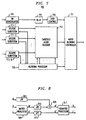
- Fig. 7 illustrates receiver 703 embracing the aforementioned mixed blending approach in accordance with the invention.
- the above host analog AM signal is demodulated using AM demodulator 705 in a conventional manner.
- the resulting analog audio signal is used as the fall back signal in the event that all of the C- and E i -streams are severely corrupted by noise and/or interference.
- the digitally modulated signals corresponding to such C- and E i - streams are fed to receive subsystems 711-1 through 711-N, respectively, where N represents the total number of streams used, and thus i ⁇ N.
- Each receive subsystem includes system components similar to those of receive circuit 507a, demodulator 509a, deinterleaver 513a, channel decoder 517a and source decoder 519a described above.
- the receive subsystems 711-1 through 711-N provide the respective streams to embedded audio decoder 713 similar to decoder 530 described before.
- Each receive subsystem also provides, to blending processor 725, flags concerning bit errors, exceptional signals concerning the signal-to-interference ratio, etc. in the corresponding stream.
- blending processor 725 Similar to blending processor 527, blending processor 725 sends control signals to decoder 713 to mute any of the streams provided thereto depending on its data integrity indicated by the frequency of the respective flags and exceptional signals, etc. However, in the event that the C-stream is not viable, blending processor 725 causes mixed blending controller 731 to output the recovered analog audio signal, enhanced by any surviving E i -streams. To that end, the surviving enhancement streams are time aligned with the analog audio signal using delay element 707. The amplitude of the analog audio signal is adjusted by gain control 709 before entering controller 731.
- Fig. 8 illustrates an effective configuration of mixed blending controller 731 where the C-stream is lost.
- the surviving enhancement streams from decoder 713 represent stereo signals having signal levels R and L, respectively. These stereo signals are used to enhance the mono-audio signal having a signal level A from gain control 709, which balances A with R and L.
- the mono-audio signal is processed by low-pass filter (LPF) 803 to filter out high frequency components thereof.
- LPF low-pass filter
- Adder 805 adds, to the filtered signal, high frequency components derived in a manner described below from the stereo signals for enhancement.
- the first output is filtered by high-pass filter (HPF) 813 to provide the aforementioned high frequency components to adder 805.
- HPF high-pass filter
- the resulting sum signal from adder 805 having a signal level M'' is provided to dematrix processor 817.
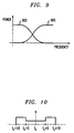
- HPF 813 and LPF 803 are power balanced (complementary) filters, with their characteristics shown in Fig. 9.
- Plots 903 and 905 represent the frequency responses of LPF 803 and HPF 813, respectively.
- the second output from processor 809 is filtered by LPF 815, rendering a filtered signal having a signal level K''.
- complementary quantizers are used to generate equivalent enhancement bit streams, e.g., E 1 -stream and E 2 -stream, for communications.
- equivalent enhancement bit streams e.g., E 1 -stream and E 2 -stream
- complementary quantizers may be used to generate equivalent C-streams, e.g., C 1 -stream and C 2 -stream, for communications.
- a(t) may be coded in accordance with the invention to yield an enhancement bit stream, and C 1 - and C 2 -streams at 8 kb/sec, 20 kb/sec and 20 kb/sec, respectively.
- subband 303 is used to transmit the C-stream. It will be appreciated that one may further subdivide, e.g., subband 303 equally for transmission of duplicate versions of the C-stream, or equivalent C-streams, to afford additional robustness to the core audio information.
- the multistream coding schemes described above are applicable to various sizes of digital bands surrounding an analog host AM carrier at f c , e.g., f c ⁇ 5 kHz, f c ⁇ 10 kHz, f c ⁇ 15 kHz, f c ⁇ 20 kHz, etc.
- multistream coding schemes described above are applicable to communications of not only audio information, but also information concerning text, graphics, video, etc.
- the multistream coding schemes, and the mixed blending technique described above are applicable not only to the hybrid IBOC AM systems, but also other systems, e.g., hybrid IBOC FM systems, satellite broadcasting systems, Internet radio systems, TV broadcasting systems, etc.
- the multistream coding schemes can be used with any other well known channel coding different than the Reed-Solomon coding described above such as the Bose-Chandhuri-Hocquenghem (BCH) coding, etc., with or without unequal error protection (UEP) sensitivity classifications.
- BCH Bose-Chandhuri-Hocquenghem
- UDP unequal error protection
- multicarrier modems 230a, 230b and 230c illustratively implement an OFDM scheme. It will be appreciated that a person skilled in the art may utilize in such a modem any other scheme such as a frequency division multiplexed tone scheme, time division multiplexed (TDM) scheme, or code division multiplexed (CDM), instead.
- OFDM frequency division multiplexed tone scheme
- TDM time division multiplexed
- CDM code division multiplexed
- the frequency subbands for transmission of individual bit streams in the multistream coding approach need not be contiguous.
- the channel coding and interleaving techniques applied to different subbands may not be identical.
- each frequency subband may be used for transmission of multiple bit streams in the multistream coding approach by time-sharing the frequency subband in accordance with a well known time division multiple access (TDMA) scheme, or by code-sharing the frequency subband in accordance with a well known code division multiple access (CDMA) scheme, or by sharing the frequency subband in another manner in accordance with a similar implicit partitioning of the subband.
- TDMA time division multiple access
- CDMA code division multiple access
- Fig. 10 illustrates an example of one such non-uniform power profile, where the power profile in the subband f c - 5 kHz through f c + 5 kHz is relatively low compared with that in the rest of the band to reduce any interference of the digitally modulated signals with the host analog AM signal occupying the same subband.
- transmitter 203, and receivers 503 and 703 are disclosed herein in a form in which various transmitter and receiver functions are performed by discrete functional blocks. However, any one or more of these functions could equally well be embodied in an arrangement in which the functions of any one or more of those blocks or indeed, all of the functions thereof, are realized, for example, by one or more appropriately programmed processors.
Landscapes
- Engineering & Computer Science (AREA)
- Signal Processing (AREA)
- Compression, Expansion, Code Conversion, And Decoders (AREA)
- Radio Relay Systems (AREA)
- Circuits Of Receivers In General (AREA)
- Digital Transmission Methods That Use Modulated Carrier Waves (AREA)
- Noise Elimination (AREA)
- Transmitters (AREA)
- Error Detection And Correction (AREA)
- Detection And Prevention Of Errors In Transmission (AREA)
Applications Claiming Priority (2)
| Application Number | Priority Date | Filing Date | Title |
|---|---|---|---|
| US280280 | 1999-03-29 | ||
| US09/280,280 US6430401B1 (en) | 1999-03-29 | 1999-03-29 | Technique for effectively communicating multiple digital representations of a signal |
Publications (2)
| Publication Number | Publication Date |
|---|---|
| EP1041766A2 true EP1041766A2 (de) | 2000-10-04 |
| EP1041766A3 EP1041766A3 (de) | 2002-09-11 |
Family
ID=23072410
Family Applications (1)
| Application Number | Title | Priority Date | Filing Date |
|---|---|---|---|
| EP00302319A Withdrawn EP1041766A3 (de) | 1999-03-29 | 2000-03-22 | Anordnung zur Übertragung von vielfachen digitalen Darstellungen eines Signals |
Country Status (4)
| Country | Link |
|---|---|
| US (2) | US6430401B1 (de) |
| EP (1) | EP1041766A3 (de) |
| JP (1) | JP2000324183A (de) |
| CA (1) | CA2300579C (de) |
Cited By (7)
| Publication number | Priority date | Publication date | Assignee | Title |
|---|---|---|---|---|
| WO2001005074A3 (de) * | 1999-07-12 | 2001-05-10 | Bosch Gmbh Robert | Verfahren zur aufbereitung von quellcodierten audiodaten sowie sender und empfanger für die durchführung dieses verfahrens |
| EP1198090A1 (de) * | 2000-10-13 | 2002-04-17 | Thales | System und Verfahren für Rundfunkübertragung, die eine Dienstleistung gewährleisten |
| GB2373151A (en) * | 2000-10-19 | 2002-09-11 | Radioscape Ltd | Hybrid analogue/digital media transmission or communication system |
| EP1394973A3 (de) * | 2002-08-27 | 2005-05-04 | Matsushita Electric Industrial Co., Ltd. | Rundfunksystem mit einem Sender und einem Empfänger für Strömen hoher Qualität und Strömen niedriger Qualität basierend auf dem gleichen Inhalt, Empfänger und Program |
| EP1455470A3 (de) * | 2003-02-20 | 2005-11-30 | Hitachi, Ltd. | Empfänger für Inhalte und Sender für Inhaltsunterschiede in einem Inhaltsverteilungssystem |
| EP1480362A4 (de) * | 2002-02-28 | 2010-09-29 | Panasonic Corp | Funkkommunikationsverfahren, funksendevorrichtung und funkempfangsvorrichtung |
| US8897195B2 (en) | 2009-03-27 | 2014-11-25 | Fujitsu Limited | Multicast data communication method and communication system |
Families Citing this family (102)
| Publication number | Priority date | Publication date | Assignee | Title |
|---|---|---|---|---|
| US8280682B2 (en) | 2000-12-15 | 2012-10-02 | Tvipr, Llc | Device for monitoring movement of shipped goods |
| US6111870A (en) * | 1996-11-07 | 2000-08-29 | Interdigital Technology Corporation | Method and apparatus for compressing and transmitting high speed data |
| US6618454B1 (en) * | 1998-02-06 | 2003-09-09 | At&T Corp. | Diversity coded OFDM for high data-rate communication |
| US6434718B1 (en) * | 1998-05-27 | 2002-08-13 | Ntt Docomo Inc. | Error protection method and error protection device |
| US6600908B1 (en) | 1999-02-04 | 2003-07-29 | Hark C. Chan | Method and system for broadcasting and receiving audio information and associated audio indexes |
| US6366888B1 (en) * | 1999-03-29 | 2002-04-02 | Lucent Technologies Inc. | Technique for multi-rate coding of a signal containing information |
| US6961432B1 (en) * | 1999-04-29 | 2005-11-01 | Agere Systems Inc. | Multidescriptive coding technique for multistream communication of signals |
| US6154452A (en) * | 1999-05-26 | 2000-11-28 | Xm Satellite Radio Inc. | Method and apparatus for continuous cross-channel interleaving |
| FR2794600B1 (fr) * | 1999-06-01 | 2001-08-17 | Thomson Multimedia Sa | Systeme de tatouage de donnees utilisant de nouvelles methodes d'insertion et de detection de tatouage |
| US7974255B2 (en) * | 1999-09-15 | 2011-07-05 | Alcatel-Lucent Usa Inc. | Method and apparatus for multi-stream transmission with time and frequency diversity in an orthogonal frequency division multiplexing (OFDM) communication system |
| US6985537B1 (en) * | 1999-09-15 | 2006-01-10 | Lucent Technologies Inc. | Symbol self synchronous interleaving method and apparatus for OFDM-based communication system |
| JP3507743B2 (ja) * | 1999-12-22 | 2004-03-15 | インターナショナル・ビジネス・マシーンズ・コーポレーション | 圧縮オーディオデータへの電子透かし方法およびそのシステム |
| FR2805102A1 (fr) * | 2000-02-16 | 2001-08-17 | Canon Kk | Procedes et dispositifs d'emission et de reception d'information, et systemes les mettant en oeuvre |
| KR100804176B1 (ko) * | 2000-03-24 | 2008-02-18 | 애서러스 커뮤니케이션즈 인코포레이티드 | 디지털통신용 디코딩 시스템 및 방법 |
| US7187947B1 (en) * | 2000-03-28 | 2007-03-06 | Affinity Labs, Llc | System and method for communicating selected information to an electronic device |
| JP2001358668A (ja) * | 2000-06-16 | 2001-12-26 | Pioneer Electronic Corp | デジタル放送用受信装置 |
| WO2002007325A1 (en) * | 2000-07-17 | 2002-01-24 | Koninklijke Philips Electronics N.V. | Signal coding |
| US9130810B2 (en) | 2000-09-13 | 2015-09-08 | Qualcomm Incorporated | OFDM communications methods and apparatus |
| US7295509B2 (en) * | 2000-09-13 | 2007-11-13 | Qualcomm, Incorporated | Signaling method in an OFDM multiple access system |
| US6684367B1 (en) * | 2000-10-13 | 2004-01-27 | Agere Systems Inc. | Channel coding based on hidden puncturing for partial-band interference channels |
| FR2821217B1 (fr) * | 2001-02-21 | 2003-04-25 | France Telecom | Procede et systeme de codage-decodage iteratif de flux de donnees numeriques codees par combinaisons spatio-temporelles, en emission et reception multiple |
| US6983151B2 (en) * | 2001-04-23 | 2006-01-03 | Telefonaktiebolaget L M Ericsson (Publ) | Method, apparatus and system for synchronization in radio communication systems |
| AU2002316435B2 (en) | 2001-06-27 | 2008-02-21 | Skky, Llc | Improved media delivery platform |
| US6996618B2 (en) * | 2001-07-03 | 2006-02-07 | Hewlett-Packard Development Company, L.P. | Method for handling off multiple description streaming media sessions between servers in fixed and mobile streaming media systems |
| US6831907B2 (en) * | 2001-08-31 | 2004-12-14 | Ericsson Inc. | Digital format U.S. commercial FM broadcast system |
| EP1430677A2 (de) * | 2001-09-26 | 2004-06-23 | General Atomics | Verfahren und einrichtung zur datenübertragung mittels eines zeitverteilungs-mehrfrequenzschemas |
| US7342973B2 (en) * | 2001-09-26 | 2008-03-11 | General Atomics | Method and apparatus for adapting multi-band ultra-wideband signaling to interference sources |
| US7609608B2 (en) * | 2001-09-26 | 2009-10-27 | General Atomics | Method and apparatus for data transfer using a time division multiple frequency scheme with additional modulation |
| US7321601B2 (en) * | 2001-09-26 | 2008-01-22 | General Atomics | Method and apparatus for data transfer using a time division multiple frequency scheme supplemented with polarity modulation |
| WO2004032600A2 (en) | 2002-02-20 | 2004-04-22 | General Atomics | Method and apparatus for data transfer using a time division multiple frequency scheme with additional modulation |
| US7043681B2 (en) * | 2002-05-03 | 2006-05-09 | Ibiquity Digital Corporation | Digital audio broadcasting method and apparatus using complementary pattern-mapped convolutional codes |
| US7177658B2 (en) * | 2002-05-06 | 2007-02-13 | Qualcomm, Incorporated | Multi-media broadcast and multicast service (MBMS) in a wireless communications system |
| EP1535440B1 (de) * | 2002-07-03 | 2008-03-12 | Telefonaktiebolaget LM Ericsson (publ) | Eingebettete eingabe |
| US7426176B2 (en) * | 2002-09-30 | 2008-09-16 | Lucent Technologies Inc. | Method of power allocation and rate control in OFDMA systems |
| KR100457188B1 (ko) * | 2002-10-07 | 2004-11-16 | 한국전자통신연구원 | 확산 방식 전환이 가능한 적응형 다중반송파코드분할다중접속 장치 및 그 방법 |
| US20040203476A1 (en) * | 2002-10-08 | 2004-10-14 | Jung-Tao Liu | Method of feedback for HSDPA system using OFMDA |
| US6901083B2 (en) * | 2002-10-25 | 2005-05-31 | Qualcomm, Incorporated | Method and system for code combining at an outer decoder on a communication system |
| US7318187B2 (en) * | 2003-08-21 | 2008-01-08 | Qualcomm Incorporated | Outer coding methods for broadcast/multicast content and related apparatus |
| US8804761B2 (en) * | 2003-08-21 | 2014-08-12 | Qualcomm Incorporated | Methods for seamless delivery of broadcast and multicast content across cell borders and/or between different transmission schemes and related apparatus |
| US8694869B2 (en) | 2003-08-21 | 2014-04-08 | QUALCIMM Incorporated | Methods for forward error correction coding above a radio link control layer and related apparatus |
| US7272189B2 (en) * | 2003-10-11 | 2007-09-18 | Visteon Global Technologies, Inc. | Method to determine the presence of multi-carrier signals |
| US7613985B2 (en) * | 2003-10-24 | 2009-11-03 | Ikanos Communications, Inc. | Hierarchical trellis coded modulation |
| US7340010B2 (en) * | 2004-01-26 | 2008-03-04 | Ibiquity Digital Corporation | Forward error correction coding for hybrid AM in-band on-channel digital audio broadcasting systems |
| US7680201B2 (en) * | 2004-01-26 | 2010-03-16 | Ibiquity Digital Corporation | Forward error correction coding for AM 9kHz and 10kHz in-band on-channel digital audio broadcasting systems |
| US9148256B2 (en) | 2004-07-21 | 2015-09-29 | Qualcomm Incorporated | Performance based rank prediction for MIMO design |
| US9137822B2 (en) | 2004-07-21 | 2015-09-15 | Qualcomm Incorporated | Efficient signaling over access channel |
| US7546088B2 (en) * | 2004-07-26 | 2009-06-09 | Ibiquity Digital Corporation | Method and apparatus for blending an audio signal in an in-band on-channel radio system |
| US9246560B2 (en) | 2005-03-10 | 2016-01-26 | Qualcomm Incorporated | Systems and methods for beamforming and rate control in a multi-input multi-output communication systems |
| US9154211B2 (en) | 2005-03-11 | 2015-10-06 | Qualcomm Incorporated | Systems and methods for beamforming feedback in multi antenna communication systems |
| US8446892B2 (en) * | 2005-03-16 | 2013-05-21 | Qualcomm Incorporated | Channel structures for a quasi-orthogonal multiple-access communication system |
| US9520972B2 (en) | 2005-03-17 | 2016-12-13 | Qualcomm Incorporated | Pilot signal transmission for an orthogonal frequency division wireless communication system |
| US9461859B2 (en) | 2005-03-17 | 2016-10-04 | Qualcomm Incorporated | Pilot signal transmission for an orthogonal frequency division wireless communication system |
| US9143305B2 (en) | 2005-03-17 | 2015-09-22 | Qualcomm Incorporated | Pilot signal transmission for an orthogonal frequency division wireless communication system |
| US9184870B2 (en) * | 2005-04-01 | 2015-11-10 | Qualcomm Incorporated | Systems and methods for control channel signaling |
| US9036538B2 (en) | 2005-04-19 | 2015-05-19 | Qualcomm Incorporated | Frequency hopping design for single carrier FDMA systems |
| US9408220B2 (en) | 2005-04-19 | 2016-08-02 | Qualcomm Incorporated | Channel quality reporting for adaptive sectorization |
| US8879511B2 (en) | 2005-10-27 | 2014-11-04 | Qualcomm Incorporated | Assignment acknowledgement for a wireless communication system |
| US8565194B2 (en) | 2005-10-27 | 2013-10-22 | Qualcomm Incorporated | Puncturing signaling channel for a wireless communication system |
| US8611284B2 (en) | 2005-05-31 | 2013-12-17 | Qualcomm Incorporated | Use of supplemental assignments to decrement resources |
| US8462859B2 (en) * | 2005-06-01 | 2013-06-11 | Qualcomm Incorporated | Sphere decoding apparatus |
| US8599945B2 (en) | 2005-06-16 | 2013-12-03 | Qualcomm Incorporated | Robust rank prediction for a MIMO system |
| US9179319B2 (en) | 2005-06-16 | 2015-11-03 | Qualcomm Incorporated | Adaptive sectorization in cellular systems |
| US8885628B2 (en) | 2005-08-08 | 2014-11-11 | Qualcomm Incorporated | Code division multiplexing in a single-carrier frequency division multiple access system |
| US9209956B2 (en) | 2005-08-22 | 2015-12-08 | Qualcomm Incorporated | Segment sensitive scheduling |
| US20070041457A1 (en) | 2005-08-22 | 2007-02-22 | Tamer Kadous | Method and apparatus for providing antenna diversity in a wireless communication system |
| US8644292B2 (en) | 2005-08-24 | 2014-02-04 | Qualcomm Incorporated | Varied transmission time intervals for wireless communication system |
| US9136974B2 (en) * | 2005-08-30 | 2015-09-15 | Qualcomm Incorporated | Precoding and SDMA support |
| US8045512B2 (en) | 2005-10-27 | 2011-10-25 | Qualcomm Incorporated | Scalable frequency band operation in wireless communication systems |
| US8477684B2 (en) | 2005-10-27 | 2013-07-02 | Qualcomm Incorporated | Acknowledgement of control messages in a wireless communication system |
| US9144060B2 (en) | 2005-10-27 | 2015-09-22 | Qualcomm Incorporated | Resource allocation for shared signaling channels |
| US8582509B2 (en) * | 2005-10-27 | 2013-11-12 | Qualcomm Incorporated | Scalable frequency band operation in wireless communication systems |
| US9225416B2 (en) | 2005-10-27 | 2015-12-29 | Qualcomm Incorporated | Varied signaling channels for a reverse link in a wireless communication system |
| US9088384B2 (en) * | 2005-10-27 | 2015-07-21 | Qualcomm Incorporated | Pilot symbol transmission in wireless communication systems |
| US9210651B2 (en) | 2005-10-27 | 2015-12-08 | Qualcomm Incorporated | Method and apparatus for bootstraping information in a communication system |
| US9172453B2 (en) | 2005-10-27 | 2015-10-27 | Qualcomm Incorporated | Method and apparatus for pre-coding frequency division duplexing system |
| US8693405B2 (en) | 2005-10-27 | 2014-04-08 | Qualcomm Incorporated | SDMA resource management |
| US9225488B2 (en) | 2005-10-27 | 2015-12-29 | Qualcomm Incorporated | Shared signaling channel |
| US8582548B2 (en) | 2005-11-18 | 2013-11-12 | Qualcomm Incorporated | Frequency division multiple access schemes for wireless communication |
| US7643895B2 (en) * | 2006-05-22 | 2010-01-05 | Apple Inc. | Portable media device with workout support |
| US8073984B2 (en) | 2006-05-22 | 2011-12-06 | Apple Inc. | Communication protocol for use with portable electronic devices |
| US20070271116A1 (en) | 2006-05-22 | 2007-11-22 | Apple Computer, Inc. | Integrated media jukebox and physiologic data handling application |
| US20080279177A1 (en) * | 2007-05-09 | 2008-11-13 | Eyal Shlomot | Conjoined Telephony Communication System |
| US8036702B2 (en) * | 2007-05-14 | 2011-10-11 | Intel Corporation | Method and apparatus for multicarrier communication in wireless systems |
| US8144683B1 (en) | 2007-11-29 | 2012-03-27 | Qualcomm Atheros, Inc. | High throughput fine timing |
| US8380531B2 (en) * | 2008-07-25 | 2013-02-19 | Invivodata, Inc. | Clinical trial endpoint development process |
| US8180470B2 (en) * | 2008-07-31 | 2012-05-15 | Ibiquity Digital Corporation | Systems and methods for fine alignment of analog and digital signal pathways |
| US20100075695A1 (en) * | 2008-09-24 | 2010-03-25 | Apple Inc. | Systems, methods, and devices for retrieving local broadcast source presets |
| US8452228B2 (en) | 2008-09-24 | 2013-05-28 | Apple Inc. | Systems, methods, and devices for associating a contact identifier with a broadcast source |
| US8886112B2 (en) * | 2008-09-24 | 2014-11-11 | Apple Inc. | Media device with enhanced data retrieval feature |
| US20100076576A1 (en) * | 2008-09-24 | 2010-03-25 | Apple Inc. | Systems, methods, and devices for providing broadcast media from a selected source |
| TWI462601B (zh) * | 2008-10-03 | 2014-11-21 | Realtek Semiconductor Corp | 音頻信號裝置及方法 |
| US20100178938A1 (en) * | 2009-01-13 | 2010-07-15 | Apple Inc. | Systems and methods for customizing radio presets |
| US20110206158A1 (en) * | 2010-02-25 | 2011-08-25 | Electronics And Telecommunications Research Institute | Transmitter and method for transmitting multiple input multiple output and receiver and method for receiving multiple input multiple output |
| US8140570B2 (en) * | 2010-03-11 | 2012-03-20 | Apple Inc. | Automatic discovery of metadata |
| DE112011101644B4 (de) * | 2010-05-13 | 2024-07-25 | Samsung Electronics Co., Ltd. | Digitalrundfunksender, Digitalrundfunkempfänger und Verfahren zum Bilden und Verarbeiten von Streams hierfür |
| US9107040B2 (en) | 2010-09-29 | 2015-08-11 | Apple Inc. | Systems, methods, and computer readable media for sharing awareness information |
| US9001804B2 (en) * | 2011-06-16 | 2015-04-07 | Qualcomm Incorporated | Sharing multi description coded content utilizing proximate helpers |
| US8948272B2 (en) | 2012-12-03 | 2015-02-03 | Digital PowerRadio, LLC | Joint source-channel decoding with source sequence augmentation |
| US9191256B2 (en) | 2012-12-03 | 2015-11-17 | Digital PowerRadio, LLC | Systems and methods for advanced iterative decoding and channel estimation of concatenated coding systems |
| US8595590B1 (en) | 2012-12-03 | 2013-11-26 | Digital PowerRadio, LLC | Systems and methods for encoding and decoding of check-irregular non-systematic IRA codes |
| WO2018064815A1 (en) * | 2016-10-08 | 2018-04-12 | Huawei Technologies Co., Ltd. | Trellis-based processing for robust digital multiband transmissions |
| CN111612265B (zh) * | 2020-05-28 | 2022-10-14 | 国家电网公司西南分部 | 考虑通道利用小时数的水电集群外送规划及运行优化方法 |
Family Cites Families (14)
| Publication number | Priority date | Publication date | Assignee | Title |
|---|---|---|---|---|
| FR1565624A (de) * | 1968-03-19 | 1969-05-02 | ||
| US3967202A (en) * | 1974-07-25 | 1976-06-29 | Northern Illinois Gas Company | Data transmission system including an RF transponder for generating a broad spectrum of intelligence bearing sidebands |
| US5887020A (en) * | 1991-05-13 | 1999-03-23 | Omnipoint Corporation | Multi-band, multi-mode spread-spectrum communication system |
| US5463641A (en) | 1993-07-16 | 1995-10-31 | At&T Ipm Corp. | Tailored error protection |
| US5442646A (en) * | 1994-02-01 | 1995-08-15 | The Mitre Corporation | Subcarrier communication system |
| US5680418A (en) * | 1994-11-28 | 1997-10-21 | Ericsson, Inc. | Removing low frequency interference in a digital FM receiver |
| US5956373A (en) * | 1995-11-17 | 1999-09-21 | Usa Digital Radio Partners, L.P. | AM compatible digital audio broadcasting signal transmision using digitally modulated orthogonal noise-like sequences |
| US5949796A (en) * | 1996-06-19 | 1999-09-07 | Kumar; Derek D. | In-band on-channel digital broadcasting method and system |
| US6005894A (en) * | 1997-04-04 | 1999-12-21 | Kumar; Derek D. | AM-compatible digital broadcasting method and system |
| US6031874A (en) * | 1997-09-26 | 2000-02-29 | Ericsson Inc. | Unequal error protection in coded modulation schemes |
| US6178317B1 (en) * | 1997-10-09 | 2001-01-23 | Ibiquity Digital Corporation | System and method for mitigating intermittent interruptions in an audio radio broadcast system |
| JP3778397B2 (ja) * | 1997-12-27 | 2006-05-24 | ソニー株式会社 | 送信方法、送信電力制御方法及び基地局装置 |
| US6108810A (en) * | 1998-03-27 | 2000-08-22 | Usa Digital Radio, Inc. | Digital audio broadcasting method using puncturable convolutional code |
| US6240275B1 (en) * | 1998-12-30 | 2001-05-29 | Ericsson Inc. | System and method for channel assignment based upon interference and channel quality measurements |
-
1999
- 1999-03-29 US US09/280,280 patent/US6430401B1/en not_active Expired - Lifetime
- 1999-04-13 US US09/290,819 patent/US6353637B1/en not_active Expired - Lifetime
-
2000
- 2000-03-13 CA CA002300579A patent/CA2300579C/en not_active Expired - Fee Related
- 2000-03-22 EP EP00302319A patent/EP1041766A3/de not_active Withdrawn
- 2000-03-28 JP JP2000089509A patent/JP2000324183A/ja active Pending
Cited By (11)
| Publication number | Priority date | Publication date | Assignee | Title |
|---|---|---|---|---|
| WO2001005074A3 (de) * | 1999-07-12 | 2001-05-10 | Bosch Gmbh Robert | Verfahren zur aufbereitung von quellcodierten audiodaten sowie sender und empfanger für die durchführung dieses verfahrens |
| EP1198090A1 (de) * | 2000-10-13 | 2002-04-17 | Thales | System und Verfahren für Rundfunkübertragung, die eine Dienstleistung gewährleisten |
| FR2815492A1 (fr) * | 2000-10-13 | 2002-04-19 | Thomson Csf | Systeme et procede de radiodiffusion assurant une continuite de service |
| US7116676B2 (en) | 2000-10-13 | 2006-10-03 | Thales | Radio broadcasting system and method providing continuity of service |
| KR100850651B1 (ko) * | 2000-10-13 | 2008-10-27 | 탈레스 | 연속서비스를 제공하는 무선 방송 시스템 및 방법 |
| GB2373151A (en) * | 2000-10-19 | 2002-09-11 | Radioscape Ltd | Hybrid analogue/digital media transmission or communication system |
| EP1480362A4 (de) * | 2002-02-28 | 2010-09-29 | Panasonic Corp | Funkkommunikationsverfahren, funksendevorrichtung und funkempfangsvorrichtung |
| EP1394973A3 (de) * | 2002-08-27 | 2005-05-04 | Matsushita Electric Industrial Co., Ltd. | Rundfunksystem mit einem Sender und einem Empfänger für Strömen hoher Qualität und Strömen niedriger Qualität basierend auf dem gleichen Inhalt, Empfänger und Program |
| US7286601B2 (en) | 2002-08-27 | 2007-10-23 | Matsushita Electric Industrial Co., Ltd. | Digital broadcast system having transmission apparatus and receiving apparatus |
| EP1455470A3 (de) * | 2003-02-20 | 2005-11-30 | Hitachi, Ltd. | Empfänger für Inhalte und Sender für Inhaltsunterschiede in einem Inhaltsverteilungssystem |
| US8897195B2 (en) | 2009-03-27 | 2014-11-25 | Fujitsu Limited | Multicast data communication method and communication system |
Also Published As
| Publication number | Publication date |
|---|---|
| US6430401B1 (en) | 2002-08-06 |
| CA2300579A1 (en) | 2000-09-29 |
| US6353637B1 (en) | 2002-03-05 |
| EP1041766A3 (de) | 2002-09-11 |
| JP2000324183A (ja) | 2000-11-24 |
| CA2300579C (en) | 2004-02-10 |
Similar Documents
| Publication | Publication Date | Title |
|---|---|---|
| EP1041766A2 (de) | Anordnung zur Übertragung von vielfachen digitalen Darstellungen eines Signals | |
| US6405338B1 (en) | Unequal error protection for perceptual audio coders | |
| EP1041756B1 (de) | Vorrichtung für die Übertragung mehrerer Datenströme im gleichen Band und Kanal | |
| US6292917B1 (en) | Unequal error protection for digital broadcasting using channel classification | |
| KR100738821B1 (ko) | 정보 비트 처리 방법 및 장치 | |
| EP0952696B1 (de) | Verfahren zur Übertragung digital modulierter Signale über ein AM-Frequenzband | |
| US6985537B1 (en) | Symbol self synchronous interleaving method and apparatus for OFDM-based communication system | |
| KR100712866B1 (ko) | 디지털 오디오 방송 및 다른 응용들을 위한 다중 프로그램디코딩 방법 및 장치 | |
| US6430724B1 (en) | Soft selection combining based on successive erasures of frequency band components in a communication system | |
| KR950007889B1 (ko) | 디지탈식 엔코트된 언어신호내의 에라 교정방법 및 시스템 | |
| KR100742102B1 (ko) | 디지털 오디오 방송 및 다른 애플리케이션들을 위한 공동 다중 프로그램 에러 은폐 방법 및 장치 | |
| JPH02504337A (ja) | 副帯域符号化におけるエネルギー情報を保護する装置 | |
| US5710781A (en) | Enhanced fading and random pattern error protection for dynamic bit allocation sub-band coding | |
| US6662339B1 (en) | Error screening based on code and control information consistency in a communication system | |
| Sinha et al. | Unequal error protection methods for perceptual audio coders | |
| Cupo et al. | An OFDM all digital In-Band-On-Channel (IBOC) AM and FM radio solution using the PAC encoder | |
| KR100783298B1 (ko) | 디지털 오디오 방송 및 다른 응용들을 위한 결합 다중프로그램 코딩 방법 및 장치 | |
| McLaughlin et al. | Speech and channel coding for digital land-mobile radio | |
| Laneman et al. | Reed-Solomon decoding algorithms for digital audio broadcasting in the AM band | |
| Naik et al. | Joint encoding and decoding methods for digital audio broadcasting of multiple programs | |
| Barron et al. | A systematic hybrid analog/digital audio coder | |
| KC | MCS MILLER COMMUNICATIONS | |
| EP1442542A1 (de) | Vorrichtung zur kodierung von hilfsinformationen in einem signal |
Legal Events
| Date | Code | Title | Description |
|---|---|---|---|
| PUAI | Public reference made under article 153(3) epc to a published international application that has entered the european phase |
Free format text: ORIGINAL CODE: 0009012 |
|
| AK | Designated contracting states |
Kind code of ref document: A2 Designated state(s): AT BE CH CY DE DK ES FI FR GB GR IE IT LI LU MC NL PT SE |
|
| AX | Request for extension of the european patent |
Free format text: AL;LT;LV;MK;RO;SI |
|
| PUAL | Search report despatched |
Free format text: ORIGINAL CODE: 0009013 |
|
| AK | Designated contracting states |
Kind code of ref document: A3 Designated state(s): AT BE CH CY DE DK ES FI FR GB GR IE IT LI LU MC NL PT SE |
|
| AX | Request for extension of the european patent |
Free format text: AL;LT;LV;MK;RO;SI |
|
| RIC1 | Information provided on ipc code assigned before grant |
Free format text: 7H 04L 5/02 A, 7H 04H 1/00 B, 7H 04L 5/06 B, 7H 04L 1/00 B |
|
| 17P | Request for examination filed |
Effective date: 20030301 |
|
| AKX | Designation fees paid |
Designated state(s): DE FR GB |
|
| APBN | Date of receipt of notice of appeal recorded |
Free format text: ORIGINAL CODE: EPIDOSNNOA2E |
|
| APBR | Date of receipt of statement of grounds of appeal recorded |
Free format text: ORIGINAL CODE: EPIDOSNNOA3E |
|
| APAF | Appeal reference modified |
Free format text: ORIGINAL CODE: EPIDOSCREFNE |
|
| RAP3 | Party data changed (applicant data changed or rights of an application transferred) |
Owner name: LUCENT TECHNOLOGIES INC. |
|
| APBT | Appeal procedure closed |
Free format text: ORIGINAL CODE: EPIDOSNNOA9E |
|
| STAA | Information on the status of an ep patent application or granted ep patent |
Free format text: STATUS: THE APPLICATION HAS BEEN WITHDRAWN |
|
| 18W | Application withdrawn |
Effective date: 20120726 |