EP1042771B1 - Verbesserter elektromagnetischer betätiger - Google Patents
Verbesserter elektromagnetischer betätiger Download PDFInfo
- Publication number
- EP1042771B1 EP1042771B1 EP98960026A EP98960026A EP1042771B1 EP 1042771 B1 EP1042771 B1 EP 1042771B1 EP 98960026 A EP98960026 A EP 98960026A EP 98960026 A EP98960026 A EP 98960026A EP 1042771 B1 EP1042771 B1 EP 1042771B1
- Authority
- EP
- European Patent Office
- Prior art keywords
- actuator
- circuit breaker
- primary
- actuator mechanism
- contacts
- Prior art date
- Legal status (The legal status is an assumption and is not a legal conclusion. Google has not performed a legal analysis and makes no representation as to the accuracy of the status listed.)
- Expired - Lifetime
Links
- 230000007246 mechanism Effects 0.000 claims abstract description 46
- 230000004907 flux Effects 0.000 claims abstract description 26
- 230000008878 coupling Effects 0.000 claims description 4
- 238000010168 coupling process Methods 0.000 claims description 4
- 238000005859 coupling reaction Methods 0.000 claims description 4
- 238000006073 displacement reaction Methods 0.000 claims description 2
- BGPVFRJUHWVFKM-UHFFFAOYSA-N N1=C2C=CC=CC2=[N+]([O-])C1(CC1)CCC21N=C1C=CC=CC1=[N+]2[O-] Chemical compound N1=C2C=CC=CC2=[N+]([O-])C1(CC1)CCC21N=C1C=CC=CC1=[N+]2[O-] BGPVFRJUHWVFKM-UHFFFAOYSA-N 0.000 description 4
- 230000009471 action Effects 0.000 description 4
- 230000000694 effects Effects 0.000 description 3
- 230000006835 compression Effects 0.000 description 2
- 238000007906 compression Methods 0.000 description 2
- 238000010586 diagram Methods 0.000 description 2
- 210000000629 knee joint Anatomy 0.000 description 2
- 230000000717 retained effect Effects 0.000 description 2
- 238000004904 shortening Methods 0.000 description 2
- 230000001960 triggered effect Effects 0.000 description 2
- 229910001209 Low-carbon steel Inorganic materials 0.000 description 1
- 229910000831 Steel Inorganic materials 0.000 description 1
- 230000001133 acceleration Effects 0.000 description 1
- 230000008901 benefit Effects 0.000 description 1
- 230000003247 decreasing effect Effects 0.000 description 1
- 238000012423 maintenance Methods 0.000 description 1
- 238000000926 separation method Methods 0.000 description 1
- 230000035939 shock Effects 0.000 description 1
- 239000010959 steel Substances 0.000 description 1
Images






Classifications
-
- H—ELECTRICITY
- H01—ELECTRIC ELEMENTS
- H01H—ELECTRIC SWITCHES; RELAYS; SELECTORS; EMERGENCY PROTECTIVE DEVICES
- H01H3/00—Mechanisms for operating contacts
- H01H3/22—Power arrangements internal to the switch for operating the driving mechanism
- H01H3/28—Power arrangements internal to the switch for operating the driving mechanism using electromagnet
-
- H—ELECTRICITY
- H01—ELECTRIC ELEMENTS
- H01H—ELECTRIC SWITCHES; RELAYS; SELECTORS; EMERGENCY PROTECTIVE DEVICES
- H01H33/00—High-tension or heavy-current switches with arc-extinguishing or arc-preventing means
- H01H33/60—Switches wherein the means for extinguishing or preventing the arc do not include separate means for obtaining or increasing flow of arc-extinguishing fluid
- H01H33/66—Vacuum switches
- H01H33/666—Operating arrangements
- H01H33/6662—Operating arrangements using bistable electromagnetic actuators, e.g. linear polarised electromagnetic actuators
-
- H—ELECTRICITY
- H01—ELECTRIC ELEMENTS
- H01H—ELECTRIC SWITCHES; RELAYS; SELECTORS; EMERGENCY PROTECTIVE DEVICES
- H01H51/00—Electromagnetic relays
- H01H51/22—Polarised relays
- H01H51/2209—Polarised relays with rectilinearly movable armature
Definitions
- the present invention relates to electromagnetic actuator devices suitable for use in operating electrical switchgear, such as vacuum circuit breakers.
- the invention has particular, though not exclusive, relevance to direct current circuit breakers and vacuum circuit breakers in general.
- High power circuit breakers require large opening and closing forces to overcome various contact forces encountered. This requires the use of large and heavy actuators which are consequently much slower to operate than their smaller equivalents. This is disadvantageous, particularly in DC circuits where a fast circuit breaking action is required.
- circuit breakers tend to wear with use
- means to accommodate an increasing relative distance between the contact surfaces when open ie. means to provide an increasing actuation distance during the lifespan of the contacts.
- This is typically achieved by providing an electromagnetic actuator which drives a moving contact through a closing spring coupling, which absorbs any difference between actuator stroke length and actual contact travel distance.
- This feature results in the creation of a snatch gap which means that the actuator does not even start to open the contacts until part way through its opening stroke, thereby slowing still further the circuit breaking operation.
- US 1956847 describes a switch and actuator mechanism in which a first and a second actuator are used to provide switch opening and closing movement, and in particular to provide rapid opening of the switch not impeded by relatively massive components of the switch closing mechanism.
- the present invention provides an actuator for a circuit breaker according to claim 1.
- the present invention provides a circuit breaker according to claims 9 and 14.
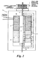
- the actuator 1 comprises a moving armature 2 coupled to, and co-axial with, a non-magnetic drive rod 3, a solenoid or coil 4 surrounding and co-axial with the armature and drive rod, a cylindrical permanent magnet 5 radially polarized and also co-axial with the armature and drive rod.
- the armature 2 and drive rod 3 are axially displaceable with respect to the coil 4 and permanent magnet 5.
- the actuator 1 is housed within a mild steel casing 6 which provides an external magnetic circuit.
- An opening spring 7 may be provided to assist in providing bias to the armature and drive rod in one direction.
- the actuator 1 is shown in figure 1 in the open contacts position, in which the armature is in the lower of two stable positions. It is held in that position by magnetic flux from the permanent magnet 5 forming a magnetic circuit as indicated by the flux path 10 (bearing double arrows) and by the opening spring 7. There is also another secondary permanent magnet flux path 11 (bearing single arrows). However, there will be very little flux in this magnetic circuit due to the presence of an air gap 15 between the armature 2 and the upper pole piece 16 of the external magnetic circuit of casing 6. The armature 2 is therefore very firmly held in the open position.
- the actuator coil 4 is energized by a pulse of direct current setting up a magnetic flux as indicated by flux path 12 (bearing triple arrows). This flux is in opposition to the permanent magnet flux 10 holding the circuit breaker open and is in the same direction as the weak permanent magnet flux 11 across the air gap 15. As the current increases in the coil 4, the point is reached where the increasing flux across the air gap 15 creates a greater attractive force than the decreasing holding force at the bottom of the actuator and the armature 2 begins to move upward. Once the armature 2 has moved, the holding force at the bottom becomes very low as an air gap 17 (figure 2) has been introduced and the air gap 15 begins to close at the top, further increasing the closing force.
- the armature 2 moves to the upper position, closing the circuit breaker and compressing the opening spring 7 during the closing stroke.
- the actuator is now in the position shown in figure 2 and is held in this position by the strong permanent magnet flux of flux path 21 (bearing double arrows).
- the permanent magnet flux through path 20 (bearing single arrows) is very low.
- the holding force is designed to be sufficiently greater than the forces of the contact pressure and opening spring 7 and the blow-open forces of short-circuit current such that under all conditions of temperature, component variation, shock etc, the circuit breaker will remain closed.
- the actuator coil is pulsed with direct current in the opposite direction to that required to close the circuit breaker, setting up the flux shown in path 22 (bearing single arrows). This flux opposes the holding flux thereby reducing the holding force to such an extent that the opening spring and contact pressure forces can cause the armature 2 to move in a downward direction.
- the trip current is generally much less than the closing current.
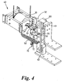
- the circuit breaker generally includes a heavy duty primary actuator 30 in conjunction with a faster acting secondary actuator 70, coupled to a contact arm of the circuit breaker by a link mechanism 50.
- the output 31 of the primary actuator 30 is coupled to the link mechanism 50 which connects the actuator 30 with a moveable contact arm 60.
- the moveable contact arm 60 is mounted on a pivot 63 and is shown in its closed condition in figures 3 and 4, biased against a non-moving contact 61 by the action of the primary actuator 30.
- An opening spring 62 provides an opening bias to the moveable contact arm 60.
- the link mechanism 50 comprises a first link arm 51 and a second link arm 52 which are pivotally attached to one another at an intermediate pivot 53 and, respectively, to the output 31 of the actuator 30 (at pivot 54) and to the moveable contact arm 60 (at pivot 55). In the contacts closed position shown, the first link arm 51 and the second link arm 52 are approximately in axial alignment with the output 31 of the actuator 30.
- the secondary actuator 70 has an actuator rod 71 which is connected to the link mechanism 50 at the intermediate pivot 53 and is displaceable by the secondary actuator stroke in a direction which is non-parallel, and preferably approximately orthogonal to, the first and second link arms. It will be understood that the actuator rod 71 need not be coupled to the link mechanism at the intermediate pivot 53, but could be coupled at any suitable position along the lengths of either the first or second link arms 51, 52 in order to vary the ratio of secondary actuator stroke length to intermediate pivot 53 displacement.
- the secondary actuator 70 is pivotally coupled to the same chassis or sub-frame (not shown) as the primary actuator 30 and contact assembly, by an anchorage 73.
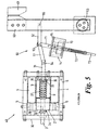
- circuit breaker 40 The function of the circuit breaker 40 will now be described with reference to the figures 5, 6 and 7, which provide a detailed schematic view of preferred embodiments of primary and secondary actuator mechanisms 30, 70 and a drive shaft connecting the primary and secondary actuators to the moveable contact 60.
- Figure 5 shows the circuit breaker in closed condition
- figure 6 shows the circuit breaker in tripped condition
- figure 7 shows the circuit breaker in open condition.
- the primary actuator 30 uses the same principles of bistable operation as described in connection with actuator 1 of figures 1 and 2, but uses an internal closing and contact pressure spring, to accommodate variations in maximum contact separation, by provision of a snatch gap. It will be understood, however, that the particular type of actuator mechanisms used for the primary and secondary actuators may be varied.
- the primary actuator 30 includes a short moving armature 2 which is in axial sliding engagement with the non-magnetic drive rod 3 which passes axially therethrough.
- the primary actuator 30 includes a coil 4, cylindrical permanent magnet 5 and a steel casing 6 which provides the external magnetic circuit.
- the actuator also includes an internal closing spring 37 which resides within a flux conducting cylinder 9.
- the armature is magnetically bistable in both left and right positions of figures 5 and 7 using similar principles as explained in connection with figures 1 and 2.
- the armature 2 transmits its leftward motion (corresponding to opening the circuit breaker) to the drive rod 3 by way of a first collar 32 attached to the drive rod 3, and transmits its rightward motion (corresponding to closing the circuit breaker) to the drive rod 3 by way of closing spring 37 and a second collar 33 attached to the drive rod 3.
- the closing spring 37 is in compression, leaving a small gap 34 between the first collar 32 and the left hand face 38 of the armature 2, and a corresponding gap 35 between the second collar 33 and the internal radial face 39 of the flux conducting cylinder 9.
- These gaps 34, 35 correspond to a degree of overtravel of the armature 2 to effect contact closure which thereby allows for contact wear and provides sufficient degree of closing spring 37 compression to give the necessary holding force to resist the blow-open forces and opening spring forces.
- the secondary actuator 70 is, in principle, a stored energy latch device which includes an actuator rod 71 coupled telescopically to the anchorage 73 which is pivotally attached to the chassis (not shown).
- the telescopic coupling includes a trip spring 72 which provides an extending bias to the telescopic connection.
- the trip spring 72 is compressed in the closed position of figure 5.
- the drive rod 71 supports a magnetic disc 75 which is normally retained by a permanent magnet flux circuit holding force provided by an electromagnetic mechanism 74 of the secondary actuator.
- the mechanism 74 also includes a coil which, upon receiving a trip signal, overcomes the permanent magnet holding flux such that the trip spring 72 can displace the rod 71 and disc 75 rapidly in an upward direction.
- the upper end of the actuator rod 71 is connected to the link mechanism 50 which connects the output 31 of the primary actuator 30 to the movable contact arm 60.
- the link mechanism 50 is preferably formed from first and second link arms 51, 52 angularly displaceable in relation to one another in the form of a knee joint about pivot 53.
- the two link arms 51, 52 together, in effect, form a variable length extension of the drive rod 3.
- the two link arms are substantially in alignment with one another and with the drive rod 3, provide a full length extension to maintain the moving contact 60 in engagement with the non-moving contact 61.
- the secondary actuator being of a faster acting type, energises its coil to overcome the permanent magnet holding force on disc 75 and thereby releases actuator rod 71 under the power of the trip spring 72. This causes the knee joint formed by link arms 51, 52 to pivot with a consequent effective shortening of the link mechanism. This occurs prior to the slower acting primary actuator commencing its opening movement, as shown in figure 6 as the intermediate "tripped" condition.
- the trip signal is generated either by a control circuit, and/or the direct current itself may be used to energise the coil in the secondary actuator 70.
- the primary current may itself flow through the secondary actuator and cause it to unlatch.
- the action of the secondary actuator 70 can be designed to have a number of effects.
- the secondary actuator 70 may have sufficient energy and stroke length to completely open the contacts 60, 61 of the circuit breaker ahead of the opening stroke of the primary actuator 30.
- the force available to open the contacts can be varied according to a number of design parameters, including: the strength of the trip spring 72; the mechanical advantage offered to the secondary actuator by the position of its connection to the link arms 51 or 52 (ie. the geometric configuration); and the strength of the closing spring 37 of the primary actuator 30 in combination with the inertial mass of the spring 37 / drive rod 3 combination and the size of gaps 34, 35.
- the secondary actuator 70 may be designed simply to close the snatch gap 34, 35 such that the primary actuator 30 is able to immediately commence movement of the drive rod 3 during its opening stroke.
- the completion of the opening stroke of the primary actuator 30 can be used to recharge or assist in recharging the trip spring 72 of the secondary actuator 70.
- the moving contact reaches its maximal opening position as shown in figure 6, the continued leftward movement of drive rod 3 acts to return the link mechanism 50 to its extended condition with or without assistance from the electromagnetic mechanism 74.
- the disc 75 is retained by the permanent magnet flux from the mechanism 74 to retain the secondary actuator 70 in its charged condition.
- link mechanism 50 can be effected in a number of different ways.
- the embodiment shown uses a knee-type joint coupled to an electromagnetic secondary actuator 70 to achieve a shortening of the effective length of the link mechanism and thus of the primary actuator overall drive shaft.
- the link mechanism 50 could, for example, alternatively be provided by a sprung telescopic link biased to a contracted condition, with a mechanical release latch which is triggered by a suitable electromechanical or electromagnetic actuator.
- the secondary actuator mechanism could be housed in the same casing as the primary actuator mechanism.
- the secondary actuator may be operative to displace a pivot point of a drive link.
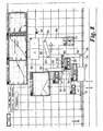
- a primary actuator 100 has an armature which is operable between a first position indicated at A, and a second position indicated at B.
- the actuator includes a spring bias toward position B indicated by spring 111.
- the primary actuator 100 is coupled, via first, second and third drive links 101, 102 and 103 to a moving contact assembly 104 of a circuit breaker, which circuit breaker also has a fixed contact assembly 105 and an opening stop 106 to limit travel of the moving contact, which fixed contact and opening stop are fixed relative to a supporting structure, not shown.
- the first and second drive links 101, 102 are pivotable relative to one another by a pivot 106; the second and third drive links 102, 103 are pivotable relative to one another by a pivot 107; and the third drive link 103 is pivotable relative to the moving contact 105 by a pivot 108.
- the second drive link 102 is also rotatable about an intermediate point along its length at pivot 109.
- the moving contact 104 is preferably pivoted about a fixed reference point relative to the supporting structure at pivot 110.
- the pivot 109 is not, however, fixed relative to the supporting structure, but moves according to a secondary actuator 120 represented in figure 8, the operation of which is described hereinafter.
- the secondary actuator 120 is operable to move between a latched position (indicated by C) as shown in figure 8 and an unlatched position (indicated by D) as shown in figure 9.
- the actuator 120 also includes a spring bias to position D, as represented by 121.
- the secondary actuator 120 and the spring 121 are operative to drive a fourth drive link 122, about a pivot 123 fixed relative to the support structure, between positions indicated by E and F (see figures 8 and 9, respectively).
- a first end of a contact spring link 125 is coupled to the drive link 122 by a pivot 124. At the other end of the contact spring link 125 is the moving pivot 109.
- the contact spring link 125 does not, however, provide a fixed distance between the pivot 124 and the pivot 109: the distance between pivot 124 and pivot 109 is extendable within predetermined limits, and is biased by a contact spring represented at 126 to an extended state. This provides for the necessary snatch gap which allows for contact wear and maintenance of contact pressure as discussed earlier.
- This extendable nature of the link can be provided in a number of ways well understood by the person skilled in the art.
- a release signal is provided to the secondary actuator 120 in similar manner to that described in connection with the secondary actuator 70 (figure 6), which causes rapid acceleration of the link 122 in an anticlockwise direction about pivot 123 under the bias of spring 121.
- the first part of this motion closes the snatch gap in the contact spring link 125; the second part of the motion opens the moving contact 104.
- the moving contact 104 has fully opened and hit the opening stop 106 preventing further movement of the moving contact.
- the secondary actuator 120 is operated, the primary actuator moves through its opening stroke from position A to position B, thereby propelling the drive link 101 so that drive link 102 rotates in a clockwise direction about moving pivot 109.
- Control of the primary actuator 100 movement may be effected in a number of ways, including electronic control.
- the opening stroke may be triggered by way of a microswitch or other device linked to the actuation of the secondary actuator.
Landscapes
- Physics & Mathematics (AREA)
- Electromagnetism (AREA)
- Driving Mechanisms And Operating Circuits Of Arc-Extinguishing High-Tension Switches (AREA)
- Reciprocating, Oscillating Or Vibrating Motors (AREA)
- Fluid-Damping Devices (AREA)
- Vehicle Body Suspensions (AREA)
- Valve Device For Special Equipments (AREA)
- Breakers (AREA)
- Moving Of Heads (AREA)
- Lock And Its Accessories (AREA)
Claims (14)
- Aktuator für einen Leistungsschalter (40) mit:wobei das Antriebsgestänge (50) aufweist:einem Antriebsgestänge (50; 102, 103) zum Ankoppeln an ein Ende eines beweglichen Kontakts (60, 105) eines Leistungsschalters;einem Primäraktuatormechanismus (30, 100), der an ein anderes Endes des Antriebsgestänges angekoppelt ist;einem Sekundäraktuatormechanismus (70, 120), der dazu vorgesehen ist, auf das Empfangen eines Triggersignals hin die Konfiguration des Antriebsgestänges zu modifizieren,wobei die Primär- und Sekundäraktuatoren (30, 70; 100, 120), miteinander in der Lage sind, eine lineare Verschiebung der Verbindungsmittel zu vermitteln, um eine Bewegung des beweglichen Kontakts zu bewirken.eine Aktuatorstange (31, 101), die an eine Armatur des Primäraktuatormechanismus 30, 100) angekoppelt ist, wobei dieser Aktuatormechanismus dazu vorgesehen ist, die Aktuatorstange in einer Richtung im Wesentlichen parallel zu seiner Längsachse anzutreiben, undVerbindungsmittel (50; 102, 103), die an ein erstes Ende der Aktuatorstange (31, 101) angekoppelt und dazu vorgesehen sind, an ein zweites Ende (55, 108) des beweglichen Kontakts (60, 104) des Leistungsschalters angekoppelt zu werden, wobei die Verbindungsmittel erste und zweite Verbindungselemente (51, 52; 102, 103) aufweisen, von denen jedes eine jeweilige erste Winkelbeziehung zu der Aktuatorstange in einem ersten Zustand und eine jeweilige zweite Winkelbeziehung zu der Aktuatorstange in einem zweiten Zustand aufweist, wobei die Änderung in den Winkelbeziehungen vorgesehen ist, um die effektive Länge der Verbindungsmittel zwischen dem Primäraktuatormechanismus (30, 100) und dem beweglichen Kontakt zu modifizieren,
- Aktuator nach Anspruch 1, wobei der Sekundäraktuatormechanismus (70, 120) ein Riegel mit gespeicherter Energie ist, der anfänglich von dem Primäraktuatormechanismus (30, 100) während seines Hubs zwischen der zweiten Position und der ersten Position beaufschlagt wird.
- Aktuator nach Anspruch 1, wobei der Sekundäraktuatormechanismus eine Spule umfasst, die zum Empfangen des Triggersignals vorgesehen ist und dadurch ausreichend Fluss erzeugt, um einen magnetischen Haltekreis zu überwinden.
- Aktuator nach Anspruch 1, wobei der Sekundäraktuatormechanismus dazu dient, die effektive Länge des Antriebsgestänges um einen Abstand zu kürzen, der mindestens genauso groß ist wie ein Schnappspalt bei dem Primäraktuatormechanismus.
- Aktuator nach Anspruch 1, wobei der Sekundäraktuatormechanismus vorgesehen ist, die Bewegung des Antriebsgestänges aus einer ersten Position in eine zweite Position zu beschleunigen, indem er einen Schnappspalt bei den Primäraktuatormechanismus während eines Öffnungshubs im Wesentlichen vor der Bewegung des Primäraktuatormechanismus absorbiert.
- Aktuator nach Anspruch 1, wobei der Sekundäraktuatormechanismus (70) einen Riegel (74) umfasst, der während des ersten Teils des Öffnungshubs ausgelöst wird, und der durch den Primäraktuatormechanismus während eines nachfolgenden Teils des Öffnungshubs zurückgesetzt wird.
- Aktuator nach Anspruch 6, wobei der Aktuatorantriebsverbindung einen Schwenkarm (102) aufweist, der um eine Achse (109) schwenkt, wobei die Position der Schwenkachse durch die Operation des Sekundäraktuatormechanismus (120) festgelegt wird.
- Aktuator nach Anspruch 7, wobei der Sekundäraktuatormechanismus an den Dreharm (120) durch ein Federglied (125) angekoppelt ist, das vorgesehen ist, um einen Schnappspalt bereitzustellen.
- Leistungsschalter (40) mit einem Aktuator nach Anspruch 1, der weiterhin ein Paar von relativ zueinander beweglichen Kontakten (60, 61; 104, 105) aufweist, wobei das Antriebsgestänge (50, 102, 103) an dem einen Ende an einen beweglichen (60, 105) der relativ zueinander beweglichen Kontakte angekoppelt ist, wobei:der Primäraktuator (30, 100) vorgesehen ist, um Schließ- und Haltekräfte für die Kontakte des Leistungsschalters bereitzustellen, undder schneller arbeitende Sekundäraktuator (70, 120) bei seinem Auslösen vorgesehen ist, ausreichend Kraft zum Öffnen oder zum Beginnen des Öffnens der Kontakte bereitzustellen.
- Leistungsschalter nach Anspruch 9, wobei der Sekundäraktuator (70, 120) einen Riegel mit gespeicherter Energie aufweist, der einen Permanentmagnetflusskreis (74, 75) zum Bereitstellen einer Haltekraft und eine Spulte umfasst, die dazu vorgesehen ist, ein Triggersignal zu Empfangen, um den permanenten Magnetfluss zu überwinden, um den Riegel auszulösen.
- Leistungsschalter nach Anspruch 10, wobei der Primäraktuator (30, 100) vorgesehen ist, den Sekundäraktuator (70, 120) während des Abschlusses eines öffnungshubs des Primäraktuators zurückzusetzen.
- Leistungsschalter nach Anspruch 11, wobei der Primäraktuator (30, 100) weiterhin vorgesehen ist, einen Schließhub für die Kontakte ohne die Unterstützung durch den Sekundäraktuator (70, 120) bereitzustellen.
- Leistungsschalter nach einem der Ansprüche 10 bis 12, wobei der Sekundäraktuatormechanismus dazu vorgesehen ist, auf das Empfangen des Triggersignals hin die effektive Länge eines Antriebsgestänges zu verkürzen.
- Leistungsschalter, der einen Aktuator gemäß einem der Ansprüche 1 bis 8 einschließt.
Applications Claiming Priority (3)
| Application Number | Priority Date | Filing Date | Title |
|---|---|---|---|
| GB9727148 | 1997-12-22 | ||
| GBGB9727148.0A GB9727148D0 (en) | 1997-12-22 | 1997-12-22 | Improvemnts in and relating to electomagnetic actuators |
| PCT/GB1998/003767 WO1999033078A1 (en) | 1997-12-22 | 1998-12-15 | Improvements in and relating to electromagnetic actuators |
Publications (2)
| Publication Number | Publication Date |
|---|---|
| EP1042771A1 EP1042771A1 (de) | 2000-10-11 |
| EP1042771B1 true EP1042771B1 (de) | 2003-02-26 |
Family
ID=10824098
Family Applications (1)
| Application Number | Title | Priority Date | Filing Date |
|---|---|---|---|
| EP98960026A Expired - Lifetime EP1042771B1 (de) | 1997-12-22 | 1998-12-15 | Verbesserter elektromagnetischer betätiger |
Country Status (12)
| Country | Link |
|---|---|
| US (1) | US6285270B1 (de) |
| EP (1) | EP1042771B1 (de) |
| AT (1) | ATE233429T1 (de) |
| AU (1) | AU747153B2 (de) |
| CA (1) | CA2316369C (de) |
| DE (1) | DE69811736T2 (de) |
| ES (1) | ES2198083T3 (de) |
| GB (2) | GB9727148D0 (de) |
| MY (1) | MY117541A (de) |
| PT (1) | PT1042771E (de) |
| WO (1) | WO1999033078A1 (de) |
| ZA (1) | ZA9811771B (de) |
Families Citing this family (50)
| Publication number | Priority date | Publication date | Assignee | Title |
|---|---|---|---|---|
| DE19910326C2 (de) * | 1999-03-09 | 2001-03-15 | E I B S A | Bistabiler magnetischer Antrieb für einen Schalter |
| FR2846469B1 (fr) * | 2002-10-23 | 2004-12-03 | Schneider Electric Ind Sas | Actionneur modulable pour appareil interrupteur |
| US7417782B2 (en) | 2005-02-23 | 2008-08-26 | Pixtronix, Incorporated | Methods and apparatus for spatial light modulation |
| US9261694B2 (en) | 2005-02-23 | 2016-02-16 | Pixtronix, Inc. | Display apparatus and methods for manufacture thereof |
| US7755582B2 (en) | 2005-02-23 | 2010-07-13 | Pixtronix, Incorporated | Display methods and apparatus |
| US20070205969A1 (en) | 2005-02-23 | 2007-09-06 | Pixtronix, Incorporated | Direct-view MEMS display devices and methods for generating images thereon |
| US7304786B2 (en) | 2005-02-23 | 2007-12-04 | Pixtronix, Inc. | Methods and apparatus for bi-stable actuation of displays |
| US9158106B2 (en) | 2005-02-23 | 2015-10-13 | Pixtronix, Inc. | Display methods and apparatus |
| US7742016B2 (en) | 2005-02-23 | 2010-06-22 | Pixtronix, Incorporated | Display methods and apparatus |
| US7999994B2 (en) | 2005-02-23 | 2011-08-16 | Pixtronix, Inc. | Display apparatus and methods for manufacture thereof |
| US7304785B2 (en) * | 2005-02-23 | 2007-12-04 | Pixtronix, Inc. | Display methods and apparatus |
| US9229222B2 (en) | 2005-02-23 | 2016-01-05 | Pixtronix, Inc. | Alignment methods in fluid-filled MEMS displays |
| US7405852B2 (en) | 2005-02-23 | 2008-07-29 | Pixtronix, Inc. | Display apparatus and methods for manufacture thereof |
| US8519945B2 (en) | 2006-01-06 | 2013-08-27 | Pixtronix, Inc. | Circuits for controlling display apparatus |
| US9082353B2 (en) | 2010-01-05 | 2015-07-14 | Pixtronix, Inc. | Circuits for controlling display apparatus |
| US7616368B2 (en) | 2005-02-23 | 2009-11-10 | Pixtronix, Inc. | Light concentrating reflective display methods and apparatus |
| US7746529B2 (en) | 2005-02-23 | 2010-06-29 | Pixtronix, Inc. | MEMS display apparatus |
| US8482496B2 (en) | 2006-01-06 | 2013-07-09 | Pixtronix, Inc. | Circuits for controlling MEMS display apparatus on a transparent substrate |
| US7271945B2 (en) * | 2005-02-23 | 2007-09-18 | Pixtronix, Inc. | Methods and apparatus for actuating displays |
| US8159428B2 (en) | 2005-02-23 | 2012-04-17 | Pixtronix, Inc. | Display methods and apparatus |
| US8310442B2 (en) | 2005-02-23 | 2012-11-13 | Pixtronix, Inc. | Circuits for controlling display apparatus |
| US7502159B2 (en) | 2005-02-23 | 2009-03-10 | Pixtronix, Inc. | Methods and apparatus for actuating displays |
| US7675665B2 (en) | 2005-02-23 | 2010-03-09 | Pixtronix, Incorporated | Methods and apparatus for actuating displays |
| US8526096B2 (en) | 2006-02-23 | 2013-09-03 | Pixtronix, Inc. | Mechanical light modulators with stressed beams |
| US7545245B2 (en) * | 2006-05-01 | 2009-06-09 | Eaton Corporation | Manual opening device and electrical switching apparatus employing the same |
| US7876489B2 (en) | 2006-06-05 | 2011-01-25 | Pixtronix, Inc. | Display apparatus with optical cavities |
| EP2080045A1 (de) | 2006-10-20 | 2009-07-22 | Pixtronix Inc. | Lichtleiter und rücklichtsysteme mit lichtumlenkern bei variierenden dichten |
| US7557682B2 (en) * | 2006-12-01 | 2009-07-07 | Eaton Corporation | Inertial solenoid delay for the opening of medium voltage circuit breakers |
| US9176318B2 (en) | 2007-05-18 | 2015-11-03 | Pixtronix, Inc. | Methods for manufacturing fluid-filled MEMS displays |
| US7852546B2 (en) | 2007-10-19 | 2010-12-14 | Pixtronix, Inc. | Spacers for maintaining display apparatus alignment |
| CN100545972C (zh) * | 2007-02-13 | 2009-09-30 | 深圳市泰永科技股份有限公司 | 一种开关转换装置及带有该装置的自动转换开关 |
| US8248560B2 (en) | 2008-04-18 | 2012-08-21 | Pixtronix, Inc. | Light guides and backlight systems incorporating prismatic structures and light redirectors |
| US8169679B2 (en) | 2008-10-27 | 2012-05-01 | Pixtronix, Inc. | MEMS anchors |
| BR112012019383A2 (pt) | 2010-02-02 | 2017-09-12 | Pixtronix Inc | Circuitos para controlar aparelho de exibição |
| WO2011097252A2 (en) | 2010-02-02 | 2011-08-11 | Pixtronix, Inc. | Methods for manufacturing cold seal fluid-filled display apparatus |
| JP5275301B2 (ja) * | 2010-08-12 | 2013-08-28 | 株式会社日立製作所 | 気中遮断器 |
| US8729985B2 (en) * | 2012-01-23 | 2014-05-20 | Electro-Mechanical Corporation | Switchgear visible disconnect mechanical interlock |
| CN102592902B (zh) * | 2012-02-22 | 2013-07-17 | 西安交通大学 | 一种中低压直流断路器的高速分闸操动机构 |
| DK2854143T3 (en) * | 2012-05-21 | 2017-04-24 | Mitsubishi Electric Corp | ELECTROMAGNETIC DEVICE AND SWITCHING DEVICE USING THE ELECTROMAGNETIC DEVICE |
| US9070517B2 (en) | 2012-08-13 | 2015-06-30 | Electro-Mechanical Corporation | Vacuum interrupter and linear disconnect switch |
| US9134552B2 (en) | 2013-03-13 | 2015-09-15 | Pixtronix, Inc. | Display apparatus with narrow gap electrostatic actuators |
| DE102013013585B4 (de) | 2013-06-20 | 2020-09-17 | Rhefor Gbr | Selbsthaltemagnet mit besonders kleiner elektrischer Auslöseleistung |
| CN109791827B (zh) * | 2016-06-24 | 2021-10-12 | 耐诺波特技术有限公司 | 触觉反馈执行器及其电子装置、操作方法 |
| KR20180064015A (ko) * | 2016-12-05 | 2018-06-14 | 엘에스산전 주식회사 | 회로 차단기 |
| CN106971914A (zh) * | 2017-05-11 | 2017-07-21 | 嘉灵开关制造(中山)有限公司 | 高分断继电器 |
| CN108091520B (zh) * | 2017-12-26 | 2024-05-14 | 福建信息职业技术学院 | 一种低功耗集成继电器开关 |
| CN118942960A (zh) * | 2018-03-28 | 2024-11-12 | 松下知识产权经营株式会社 | 电路切断装置 |
| AU2020215624B2 (en) * | 2019-01-31 | 2021-05-20 | S&C Electric Company | Manual close assist control mechanism |
| KR102248495B1 (ko) * | 2020-02-12 | 2021-05-04 | 송기현 | 저자력 영구자석 액츄에이터 |
| CN111261433A (zh) * | 2020-03-20 | 2020-06-09 | 无锡立成电器有限公司 | 三工位开关柜隔离操作机构 |
Family Cites Families (5)
| Publication number | Priority date | Publication date | Assignee | Title |
|---|---|---|---|---|
| US1956847A (en) * | 1930-05-31 | 1934-05-01 | Condit Electrical Mfg Corp | Electric switch and switch actuating mechanism |
| FR2112415B1 (de) * | 1970-11-03 | 1976-07-23 | Hartmann & Braun Ag | |
| JPS59158506A (ja) * | 1983-02-28 | 1984-09-08 | Toshiba Corp | 電磁石装置 |
| ES2011457B3 (es) * | 1985-12-13 | 1990-01-16 | Cmc Carl Maier + Cie Ag | Desconexion de iman para interruptores de proteccion de corriente de defecto |
| US5172088A (en) * | 1992-02-06 | 1992-12-15 | General Electric Company | Molded case circuit breaker combined accessory actuator-reset lever |
-
1997
- 1997-12-22 GB GBGB9727148.0A patent/GB9727148D0/en not_active Ceased
-
1998
- 1998-12-15 PT PT98960026T patent/PT1042771E/pt unknown
- 1998-12-15 DE DE69811736T patent/DE69811736T2/de not_active Expired - Lifetime
- 1998-12-15 CA CA002316369A patent/CA2316369C/en not_active Expired - Fee Related
- 1998-12-15 WO PCT/GB1998/003767 patent/WO1999033078A1/en not_active Ceased
- 1998-12-15 ES ES98960026T patent/ES2198083T3/es not_active Expired - Lifetime
- 1998-12-15 EP EP98960026A patent/EP1042771B1/de not_active Expired - Lifetime
- 1998-12-15 AT AT98960026T patent/ATE233429T1/de not_active IP Right Cessation
- 1998-12-15 AU AU15713/99A patent/AU747153B2/en not_active Expired
- 1998-12-15 US US09/582,151 patent/US6285270B1/en not_active Expired - Lifetime
- 1998-12-15 GB GB0015409A patent/GB2347272B/en not_active Expired - Lifetime
- 1998-12-21 MY MYPI98005799A patent/MY117541A/en unknown
- 1998-12-22 ZA ZA9811771A patent/ZA9811771B/xx unknown
Also Published As
| Publication number | Publication date |
|---|---|
| CA2316369C (en) | 2006-12-05 |
| MY117541A (en) | 2004-07-31 |
| GB2347272B (en) | 2001-10-17 |
| AU1571399A (en) | 1999-07-12 |
| GB0015409D0 (en) | 2000-08-16 |
| AU747153B2 (en) | 2002-05-09 |
| DE69811736D1 (de) | 2003-04-03 |
| PT1042771E (pt) | 2003-07-31 |
| DE69811736T2 (de) | 2003-10-23 |
| ATE233429T1 (de) | 2003-03-15 |
| GB2347272A (en) | 2000-08-30 |
| US6285270B1 (en) | 2001-09-04 |
| ES2198083T3 (es) | 2004-01-16 |
| EP1042771A1 (de) | 2000-10-11 |
| CA2316369A1 (en) | 1999-07-01 |
| WO1999033078A1 (en) | 1999-07-01 |
| ZA9811771B (en) | 2000-10-10 |
| GB9727148D0 (en) | 1998-02-25 |
Similar Documents
| Publication | Publication Date | Title |
|---|---|---|
| EP1042771B1 (de) | Verbesserter elektromagnetischer betätiger | |
| KR100568906B1 (ko) | 전자기 액츄에이터 | |
| US7843293B1 (en) | Bistable magnetic drive for a switch | |
| CN102947908A (zh) | 带有超快致动机构的电气开关装置及包括该装置的混合开关 | |
| EP3761337A1 (de) | Elektromagnetischer betätiger, schalter und schaltgetriebe | |
| US12394582B2 (en) | Multi-part moving shaft assembly for ultra high speed actuator used in a hybrid circuit breaker | |
| GB1290386A (de) | ||
| US4180788A (en) | Vacuum circuit breaker with delayed trip operation | |
| HK77485A (en) | Contactor device with means for automatic interruption and with a local operating part | |
| CN220382023U (zh) | 用于塑壳断路器的行程控制机构及塑壳断路器 | |
| US5554962A (en) | DC vacuum relay device with angular impact break mechanism | |
| CA2563695C (en) | Fault interrupter and disconnect device | |
| JP3180508B2 (ja) | 遮断器の制御装置 | |
| CN221613728U (zh) | 开关电器 | |
| CN208781729U (zh) | 一种快速开关分合闸操作机构 | |
| JP4627417B2 (ja) | 電力用遮断器 | |
| CN221613730U (zh) | 开关电器 | |
| CN223956541U (zh) | 一种快速分闸开关 | |
| WO2026000776A1 (zh) | 一种电的开关 | |
| CN120280290A (zh) | 开关电器 | |
| CN121439628A (zh) | 一种用于微电网的快速开关 | |
| CN121439632A (zh) | 一种组合式断路器 | |
| CN120280291A (zh) | 开关电器 | |
| CN121416379A (zh) | 一种机电驱动双稳态操作机构及快速断路器 | |
| JP6922673B2 (ja) | 遮断器 |
Legal Events
| Date | Code | Title | Description |
|---|---|---|---|
| PUAI | Public reference made under article 153(3) epc to a published international application that has entered the european phase |
Free format text: ORIGINAL CODE: 0009012 |
|
| 17P | Request for examination filed |
Effective date: 20000703 |
|
| AK | Designated contracting states |
Kind code of ref document: A1 Designated state(s): AT BE CH DE DK ES FR IE IT LI LU NL PT SE |
|
| 17Q | First examination report despatched |
Effective date: 20010102 |
|
| RAP1 | Party data changed (applicant data changed or rights of an application transferred) |
Owner name: FKI PLC |
|
| GRAG | Despatch of communication of intention to grant |
Free format text: ORIGINAL CODE: EPIDOS AGRA |
|
| GRAG | Despatch of communication of intention to grant |
Free format text: ORIGINAL CODE: EPIDOS AGRA |
|
| GRAH | Despatch of communication of intention to grant a patent |
Free format text: ORIGINAL CODE: EPIDOS IGRA |
|
| GRAH | Despatch of communication of intention to grant a patent |
Free format text: ORIGINAL CODE: EPIDOS IGRA |
|
| GRAA | (expected) grant |
Free format text: ORIGINAL CODE: 0009210 |
|
| AK | Designated contracting states |
Designated state(s): AT BE CH DE DK ES FR IE IT LI LU NL PT SE |
|
| PG25 | Lapsed in a contracting state [announced via postgrant information from national office to epo] |
Ref country code: FR Free format text: LAPSE BECAUSE OF NON-PAYMENT OF DUE FEES Effective date: 20030226 Ref country code: BE Free format text: LAPSE BECAUSE OF FAILURE TO SUBMIT A TRANSLATION OF THE DESCRIPTION OR TO PAY THE FEE WITHIN THE PRESCRIBED TIME-LIMIT Effective date: 20030226 Ref country code: AT Free format text: LAPSE BECAUSE OF FAILURE TO SUBMIT A TRANSLATION OF THE DESCRIPTION OR TO PAY THE FEE WITHIN THE PRESCRIBED TIME-LIMIT Effective date: 20030226 |
|
| REG | Reference to a national code |
Ref country code: CH Ref legal event code: EP |
|
| REG | Reference to a national code |
Ref country code: IE Ref legal event code: FG4D |
|
| REF | Corresponds to: |
Ref document number: 69811736 Country of ref document: DE Date of ref document: 20030403 Kind code of ref document: P |
|
| REG | Reference to a national code |
Ref country code: CH Ref legal event code: NV Representative=s name: KIRKER & CIE SA |
|
| PG25 | Lapsed in a contracting state [announced via postgrant information from national office to epo] |
Ref country code: SE Free format text: LAPSE BECAUSE OF FAILURE TO SUBMIT A TRANSLATION OF THE DESCRIPTION OR TO PAY THE FEE WITHIN THE PRESCRIBED TIME-LIMIT Effective date: 20030526 Ref country code: DK Free format text: LAPSE BECAUSE OF FAILURE TO SUBMIT A TRANSLATION OF THE DESCRIPTION OR TO PAY THE FEE WITHIN THE PRESCRIBED TIME-LIMIT Effective date: 20030526 |
|
| PG25 | Lapsed in a contracting state [announced via postgrant information from national office to epo] |
Ref country code: LU Free format text: LAPSE BECAUSE OF NON-PAYMENT OF DUE FEES Effective date: 20031215 |
|
| PLBE | No opposition filed within time limit |
Free format text: ORIGINAL CODE: 0009261 |
|
| STAA | Information on the status of an ep patent application or granted ep patent |
Free format text: STATUS: NO OPPOSITION FILED WITHIN TIME LIMIT |
|
| REG | Reference to a national code |
Ref country code: ES Ref legal event code: FG2A Ref document number: 2198083 Country of ref document: ES Kind code of ref document: T3 |
|
| EN | Fr: translation not filed | ||
| 26N | No opposition filed |
Effective date: 20031127 |
|
| PGFP | Annual fee paid to national office [announced via postgrant information from national office to epo] |
Ref country code: NL Payment date: 20081203 Year of fee payment: 11 Ref country code: IE Payment date: 20081216 Year of fee payment: 11 |
|
| PGFP | Annual fee paid to national office [announced via postgrant information from national office to epo] |
Ref country code: PT Payment date: 20081204 Year of fee payment: 11 |
|
| REG | Reference to a national code |
Ref country code: PT Ref legal event code: MM4A Free format text: LAPSE DUE TO NON-PAYMENT OF FEES Effective date: 20100615 |
|
| REG | Reference to a national code |
Ref country code: NL Ref legal event code: V1 Effective date: 20100701 |
|
| PG25 | Lapsed in a contracting state [announced via postgrant information from national office to epo] |
Ref country code: PT Free format text: LAPSE BECAUSE OF NON-PAYMENT OF DUE FEES Effective date: 20100615 |
|
| REG | Reference to a national code |
Ref country code: IE Ref legal event code: MM4A |
|
| PG25 | Lapsed in a contracting state [announced via postgrant information from national office to epo] |
Ref country code: NL Free format text: LAPSE BECAUSE OF NON-PAYMENT OF DUE FEES Effective date: 20100701 Ref country code: IE Free format text: LAPSE BECAUSE OF NON-PAYMENT OF DUE FEES Effective date: 20091215 |
|
| REG | Reference to a national code |
Ref country code: DE Ref legal event code: R082 Ref document number: 69811736 Country of ref document: DE Representative=s name: REHBERG HUEPPE + PARTNER PATENTANWAELTE, DE Effective date: 20110922 Ref country code: DE Ref legal event code: R082 Ref document number: 69811736 Country of ref document: DE Representative=s name: REHBERG HUEPPE + PARTNER PATENTANWAELTE PARTG , DE Effective date: 20110922 Ref country code: DE Ref legal event code: R081 Ref document number: 69811736 Country of ref document: DE Owner name: HAWKER SIDDELEY SWITCHGEAR LTD., GB Free format text: FORMER OWNER: FKI PLC, LONDON, GB Effective date: 20110922 Ref country code: DE Ref legal event code: R081 Ref document number: 69811736 Country of ref document: DE Owner name: HAWKER SIDDELEY SWITCHGEAR LTD., ALCESTER, GB Free format text: FORMER OWNER: FKI PLC, LONDON, GB Effective date: 20110922 |
|
| REG | Reference to a national code |
Ref country code: ES Ref legal event code: PC2A Owner name: HAWKER SIDDELEY SWITCHGEAR LIMITED Effective date: 20130218 |
|
| REG | Reference to a national code |
Ref country code: CH Ref legal event code: PUE Owner name: HAWKER SIDDELEY SWITCHGEAR LIMITED, GB Free format text: FORMER OWNER: FKI PLC, GB Ref country code: CH Ref legal event code: NV Representative=s name: KIRKER AND CIE S.A., CH |
|
| PGFP | Annual fee paid to national office [announced via postgrant information from national office to epo] |
Ref country code: DE Payment date: 20171212 Year of fee payment: 20 |
|
| PGFP | Annual fee paid to national office [announced via postgrant information from national office to epo] |
Ref country code: CH Payment date: 20171212 Year of fee payment: 20 |
|
| PGFP | Annual fee paid to national office [announced via postgrant information from national office to epo] |
Ref country code: ES Payment date: 20180102 Year of fee payment: 20 |
|
| PGFP | Annual fee paid to national office [announced via postgrant information from national office to epo] |
Ref country code: IT Payment date: 20171221 Year of fee payment: 20 |
|
| REG | Reference to a national code |
Ref country code: CH Ref legal event code: PL |
|
| REG | Reference to a national code |
Ref country code: DE Ref legal event code: R071 Ref document number: 69811736 Country of ref document: DE |
|
| REG | Reference to a national code |
Ref country code: ES Ref legal event code: FD2A Effective date: 20200902 |
|
| PG25 | Lapsed in a contracting state [announced via postgrant information from national office to epo] |
Ref country code: ES Free format text: LAPSE BECAUSE OF EXPIRATION OF PROTECTION Effective date: 20181216 |