EP1042861B1 - Vorrichtung und verfahren zur detektion von zuvor entstandenen digitalen pcm-fehlern in einem kommunikationsnetz - Google Patents
Vorrichtung und verfahren zur detektion von zuvor entstandenen digitalen pcm-fehlern in einem kommunikationsnetz Download PDFInfo
- Publication number
- EP1042861B1 EP1042861B1 EP98959517A EP98959517A EP1042861B1 EP 1042861 B1 EP1042861 B1 EP 1042861B1 EP 98959517 A EP98959517 A EP 98959517A EP 98959517 A EP98959517 A EP 98959517A EP 1042861 B1 EP1042861 B1 EP 1042861B1
- Authority
- EP
- European Patent Office
- Prior art keywords
- digital
- octets
- logic
- pcm
- tables
- Prior art date
- Legal status (The legal status is an assumption and is not a legal conclusion. Google has not performed a legal analysis and makes no representation as to the accuracy of the status listed.)
- Expired - Lifetime
Links
- 230000006735 deficit Effects 0.000 title claims description 120
- 238000011144 upstream manufacturing Methods 0.000 title claims description 72
- 238000000034 method Methods 0.000 title claims description 43
- 238000004891 communication Methods 0.000 title claims description 36
- 230000005540 biological transmission Effects 0.000 claims description 31
- 230000011664 signaling Effects 0.000 claims description 30
- 238000009826 distribution Methods 0.000 claims description 17
- 238000012549 training Methods 0.000 claims description 17
- 238000013139 quantization Methods 0.000 claims description 9
- 238000001914 filtration Methods 0.000 claims 5
- 101100467813 Saccharomyces cerevisiae (strain ATCC 204508 / S288c) RBS1 gene Proteins 0.000 description 28
- 238000001514 detection method Methods 0.000 description 23
- 238000010586 diagram Methods 0.000 description 23
- 239000008186 active pharmaceutical agent Substances 0.000 description 14
- 230000001771 impaired effect Effects 0.000 description 5
- 238000011045 prefiltration Methods 0.000 description 4
- 230000006978 adaptation Effects 0.000 description 3
- 239000000523 sample Substances 0.000 description 3
- 230000001360 synchronised effect Effects 0.000 description 3
- 230000008859 change Effects 0.000 description 2
- 230000000116 mitigating effect Effects 0.000 description 2
- 230000004044 response Effects 0.000 description 2
- 238000005070 sampling Methods 0.000 description 2
- 238000012935 Averaging Methods 0.000 description 1
- 230000003044 adaptive effect Effects 0.000 description 1
- 230000008901 benefit Effects 0.000 description 1
- 230000002457 bidirectional effect Effects 0.000 description 1
- 238000007405 data analysis Methods 0.000 description 1
- 238000013461 design Methods 0.000 description 1
- 230000006870 function Effects 0.000 description 1
- 230000009022 nonlinear effect Effects 0.000 description 1
- 230000008569 process Effects 0.000 description 1
- 238000012545 processing Methods 0.000 description 1
Images







Classifications
-
- H—ELECTRICITY
- H04—ELECTRIC COMMUNICATION TECHNIQUE
- H04B—TRANSMISSION
- H04B17/00—Monitoring; Testing
-
- H—ELECTRICITY
- H04—ELECTRIC COMMUNICATION TECHNIQUE
- H04J—MULTIPLEX COMMUNICATION
- H04J3/00—Time-division multiplex systems
- H04J3/02—Details
- H04J3/12—Arrangements providing for calling or supervisory signals
- H04J3/125—One of the channel pulses or the synchronisation pulse is also used for transmitting monitoring or supervisory signals
-
- H—ELECTRICITY
- H04—ELECTRIC COMMUNICATION TECHNIQUE
- H04B—TRANSMISSION
- H04B14/00—Transmission systems not characterised by the medium used for transmission
- H04B14/02—Transmission systems not characterised by the medium used for transmission characterised by the use of pulse modulation
- H04B14/04—Transmission systems not characterised by the medium used for transmission characterised by the use of pulse modulation using pulse code modulation
-
- H—ELECTRICITY
- H04—ELECTRIC COMMUNICATION TECHNIQUE
- H04L—TRANSMISSION OF DIGITAL INFORMATION, e.g. TELEGRAPHIC COMMUNICATION
- H04L25/00—Baseband systems
- H04L25/38—Synchronous or start-stop systems, e.g. for Baudot code
- H04L25/40—Transmitting circuits; Receiving circuits
- H04L25/49—Transmitting circuits; Receiving circuits using code conversion at the transmitter; using predistortion; using insertion of idle bits for obtaining a desired frequency spectrum; using three or more amplitude levels ; Baseband coding techniques specific to data transmission systems
- H04L25/4917—Transmitting circuits; Receiving circuits using code conversion at the transmitter; using predistortion; using insertion of idle bits for obtaining a desired frequency spectrum; using three or more amplitude levels ; Baseband coding techniques specific to data transmission systems using multilevel codes
- H04L25/4927—Transmitting circuits; Receiving circuits using code conversion at the transmitter; using predistortion; using insertion of idle bits for obtaining a desired frequency spectrum; using three or more amplitude levels ; Baseband coding techniques specific to data transmission systems using multilevel codes using levels matched to the quantisation levels of the channel
Definitions
- This invention relates to a device and method for detecting PCM upstream digital impairments and using the detected impairments to estimate the analog channel characteristics and PCM downstream echo to improve PCM upstream transmission.
- PCM modems such as V.34 modems
- PSTN public switched telephone network
- PCM modems take advantage of the fact that most of the network is digital and that typically central site modems, such as those of internet service providers and on-line services, are connected to the PSTN via digital connections (e.g., T1 in the United States and E1 in Europe).
- First generation PCM modems transmit data in PCM mode downstream only (i.e., from a central site digital modem to an analog end user modem) and transmit in analog mode, e.g. V.34 mode, upstream (i.e., from the end modem to the central site modem).
- Second generation PCM modems will also transmit data upstream in PCM mode.
- the central site PCM modem transmits over a digital network eight bit digital words (octets) corresponding to different central office codec output levels.
- the octets are converted to analog levels which are transmitted over an analog loop.
- the end user's PCM modem then converts the analog levels into equalized digital levels.
- the equalized digital levels are ideally mapped back into the originally transmitted octets and the data the octets represent.
- the end user PCM modem transmits analog levels over the analog loop corresponding to the data to be transmitted and the levels are quantized to form octets by a codec in the end user's central office.
- the codec transmits the octets to the PCM central site modem over the digital network.
- modem digital networks which may carry PCM modem data are constructed as T-carrier systems that use robbed bit signaling.
- the digital data transmitted over these networks is grouped into octets (eight (8) bits) and the octets are grouped into frames (twenty four (24) octets).
- FIG. 1 there is shown a frame 10 containing twenty four octets, O 0 -O 23 .
- the frames transmitted over the network are continuous, and the single 24 octet frame 10 is shown for descriptive convenience only.
- Certain octets are affected by RBS.
- the network uses the least significant bit (LSB) position of the affected octets to carry data to perform control functions in the network.
- LSB least significant bit
- the first octet, O 0 may be affected by a type of RBS that forces the LSB of that octet to one, odd RBS, as indicated by the "F” in that octet.
- the designation "NC” means "no change”
- RBS may change that octet's data. In particular, if that octet had a zero in its LSB, RBS alters that octet. If, however, that octet had a one in its LSB, RBS would have no affect on the octet from the end-user's perspective.
- RBS has deterministic periodicity with periods of six or twenty four octets.
- the RBS period is twenty four. Since RBS recurs every twenty four octets, the octets can be viewed as appearing in a basic period 12 of twenty four time slots or intervals, 0-23, which may or may not be affected by RBS. For example, octet O 0 appears in slot "0" which is affected by RBS, while octet O 1 , for example, appears in slot "1" and is unaffected by RBS. It should be noted that due to the nature of the networks, it is possible to have more than one RBS affected interval in the basic period of twenty four, as evidenced by affected octet O 6 .
- downstream transmission With downstream transmission, the points transmitted over the digital network are known and this information is used for digital impairment detection according to the above referenced applications.
- upstream transmission before determining digital impairments, downstream PCM echo and the characteristics of the analog loop (channel), the points transmitted over the digital channel are unknown and the techniques for detecting digital impairments described in the above applications are not applicable to upstream transmission.
- US 5,528,679 discloses a method and apparatus for determining whether a sufficiently clear digital path exists from a first end user to a second end user when connecting a call over a switched telephone network. Once the determination is made, the type of connection that is possible (high speed digital or analog compatible rates) can be determined. The characteristics of a path between two subscribers on a telephone network are determined by transmitting a digital probe along the path.
- EP-A-0 735 716 discloses a timing technique for a Quantization-Level-Sampling (QLS) modem that puts timing information in a downstream pulsed signal transmitted from the public switched telephone network (PSTN) to the QLS modem.
- the QLS modem synchronizes to the network sampling clock of the PSTN.
- the pulsed signal includes data-bearing samples, which were provided by a far-end QLS modem, and at least one non-user-data-bearing (NUDB) sample in which the level of this NUDB sample periodically alternates.
- NUDB non-user-data-bearing
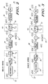
- FIG. 2 there is shown block diagram 20, an example of PCM upstream transmission in such a bidirectional PCM communication system.
- analog PCM modem 22 having a precoder 24, prefilter 25 and a digital to analog converter (D/A) 26, interconnected to analog channel 28.
- Precoder 24 receives digital data u(n) and outputs precoded data x(n).
- the precoded digital data is provided to prefilter 25 which outputs filtered signal z(n).
- Filtered signal z(n) is converted to analog form and is transmitted as signal, z(t), over analog channel 28, having a channel characteristic, c(t).
- the analog channel modifies the transmitted signal z(t) to form signal y(t) which then encounters downstream PCM echo, echo(t) 30, that is added to y(t), producing signal r(t).
- Signal r(t) is received by ⁇ -law (A-law in most countries outside of the U.S.) quantizer 34 in central office (CO) 32 and is quantized according to the ⁇ -law. See International Telecommunications Union, Recommendation G.711, Pulse Code Modulation (PCM) of Voice Frequencies, 1972.
- PCM Pulse Code Modulation
- the quantized octets (digital values), q(n), are transmitted over digital network 36 at a frequency of 8 kHz where they may be affected by various digital impairments, as discussed below.
- the possibly affected octets, v(n) are received by digital PCM modem 38 which ideally decodes the octets, v(n), into the original digital data, u(n).
- the clock (f 1 ) of D/A 26 in analog PCM modem 22 must be synchronized to the clock (f 2 ) of CO 32. This can be achieved by learning the clock from the downstream PCM signal (not shown) and synchronizing the clocks using the technique proposed in U.S. Pat. No. 5,199,046 , entitled First and Second Digital Rate Converter Synchronization Device and Method.
- PCM upstream block diagram 20, FIG. 2 can be represented as equivalent discrete time block diagram 20', FIG. 3 , with like components being represented by the same reference numbers containing a prime (').
- f 1 f 2 ; however, it must be noted that f 1 does not have to be equal to f 2 as long as the two clocks are synchronized.
- n is the time index for 8 kHz samples, since the clock (f 2 ) of CO 32 is fixed at that frequency.
- Precoder 24 (24') and prefilter 25 (25') may be implemented as described in co-pending application US patent no. 6,198,776 entitled Device and Method for Precoding Data Signals for Pulse Code Modulation (PCM) Transmission, which is assigned to the assignee of the present invention.
- digital data u(n) may be sent by transmitting z(n) such that the constellation points y(n) will be one of a number of points in an equivalence class for u(n).
- the point y(n) in the equivalence class of u(n) that is selected is usually determined to minimize the transmit power which is the power of x(n).
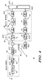
- Discrete time block diagram 40 shows the equivalent discrete upstream block diagram 20' together with the echo path 42 caused by downstream transmission from digital PCM modem 38'.
- Digital PCM modem 38' transmits octets, s(n), downstream over digital network 36'.
- the octets s(n) may be affected by digital impairments, such as robbed bit signaling and digital loss in digital network 36', causing the octets s(n) to be modified.
- DS RBS1 44 a first occurrence of RBS, designated DS RBS1 44, which occurs before digital loss, designated DS digital loss 46, and a second occurrence of RBS, designated DS RBS2 48.
- the octets exiting digital network 36' are designated p(n).
- the possible types of DS RBS2 48 are no RBS, even RBS, odd RBS and midpoint reconstruction RBS.
- RBS may vary according to time slot.
- digital loss is not time varying, i.e. the digital loss is the same for all time slots.
- downstream channel 43 of digital network 36' may be unaffected by digital loss, often referred to as 0 dB loss. The most common types are 3 dB and 6 dB loss and no digital loss (0 dB).
- DS RBS1 44 The detection of downstream digital impairments, i.e. DS RBS1 44, DS digital loss 46, DS RBS2 48, can be found in the co-pending patent applications referred to above.
- the octets, p(n), exiting digital network 36' are received by ⁇ -law digital to analog converter (D/A) 50 in CO 32' which outputs corresponding analog levels ( ⁇ -law levels) that are transmitted to analog PCM modem 22'.
- D/A digital to analog converter
- This portion of the downstream transmission is not depicted; however, the echo, echo (n) 30', produced by the downstream transmission, represented by echo channel 52 (with channel characteristic h(n)), is shown.
- the downstream PCM echo, echo (n) 30' is added to the output of the analog channel y(n) to form the signal r(n) which is input to ⁇ -law quantizer 34' in central office (CO) 32'.
- the signal r(n) is quantized by ⁇ -law quantizer 34' which outputs ⁇ -law octets, q(n), over upstream channel 53 of digital network 36'.
- a first occurrence of RBS designated US RBS 1 54, which occurs before digital loss, designated US digital loss 56, and a second occurrence of RBS, designated US RBS2 58.
- the possible types of US RBS2 58 are no RBS, even RBS, and odd RBS.
- Midpoint reconstruction RBS does not occur in the upstream channel.
- the possible types of US digital loss are the same as on the downstream channel. The most common types in the United States are 3 dB and 6 dB loss and no digital loss (0 dB) and this invention is described with regard to these losses. However, the principles of the invention may be readily applied to any level of digital loss.
- upstream digital impairments i.e., US RBS1 54, US digital loss 56, and US RBS2 58, according to this invention.
- the estimation of the analog channel, c(n) in the presence of these detected digital impairments and the estimation of the downstream PCM echo, echo (n), introduced into the upstream PCM transmission, and echo variance, ⁇ e 2 , according to this invention, are described.
- the upstream digital impairments, the estimation of the analog channel, c(n), and echo variance are transmitted to analog PCM modem and may be used by that modem to select the appropriate transmit constellation, as described in co-pending patent application US Apl. Ser. No. 08/994,254 .
- the upstream digital impairments, the estimation of the analog channel, c(n), and the echo variance may alternatively be used by the digital PCM modem to improve decoding performance.
- a random training sequence, z(n), is one that produces signals y(n) with an essentially Gaussian distribution that excites most of the 256 ⁇ -law points in ⁇ -law quantizer 34' randomly. Because of loss in analog channel 28' some of the larger ⁇ -law points may not be excited.
- the phase 2 line probing tone sequence specified in the ITU V.34 analog modem specification may be used, for example.
- the signal r(n) (or y(n) in the absence of echo (n) 30') will be quantized, q(n), by the ⁇ -law quantizer 34'.
- the octets, q(n) pass through digital network 36' and digital modem 38' receives v(n), the digitally impaired version of q(n). Since the digital impairments are unknown, q(n) cannot be derived from v(n).
- the basic idea of detecting upstream digital impairments by PCM digital modem 38' involves observing the distribution of received octets v(n) at each RBS time slot during the training sequence, or after it is completed, to determine the impairments, both RBS and digital loss, affecting the upstream PCM channel of the digital communication network during each RBS time slot.
- a preferred technique for detecting digital impairments according to this invention is described as follows.
- a distribution of received octets v(n) for each RBS time slot is collected by, for example, establishing an occurrence table 60, FIG. 5 , that maintains a count of the number of times each of the possible received octets 0-127 (the constellation of digital values) have been received in each RBS time slot.
- the received octets are converted to bit inverted octet (BIOS) form.
- each bit of the received octets is inverted and all octets referred to herein are assumed to be in BIOS form unless otherwise specified.
- BIOS form ⁇ -law octets 0-127 are positive octets and 128-255 are negative octets.
- occurrence table 60 a count of the number of times each octet is received, regardless of its sign, is maintained to form a distribution of received octets v(n).
- certain ⁇ -law octets will not be received.
- ⁇ -law octets 1, 3 ... and 127 have zero occurrences, meaning that digital modem 38' has not received these ⁇ -law octets.
- the other ⁇ -law octets shown, namely, 0, 2 ... and 4 have been received X 0 , X 2 , X 4 ... times, respectively.
- the distributions of received octets v(n) are analyzed to determine the impairments affecting the upstream PCM channel of the digital communication network.
- a combination of impairments may be referred to herein as an impairment condition.
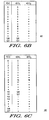
- an inverse digital-impairment table whose first column contains all possible octets v(n), 0-127, that may be received by digital modem 38' and the remaining columns are the possible q(n) octet(s) input to the digital network 36' that produce the received octets v(n) under the specified impairment condition of the table.
- RBS1 No RBS
- digital loss 0dB
- RBS2 1._
- ⁇ -law octets q(n) 1 and q(n) 2 , 0 and 1 input to a digital network affected by the above impairment condition, will be mapped to a single received octet v(n), 0.
- v(n) due to the impairment condition in the network, there are certain octets, v(n), that cannot be received, regardless of the ⁇ -law octets input to the digital network.
- null point entries there are no q(n) entries in the IDT table corresponding to these octets, v(n). These nonexistent q(n) entries are referred to herein as null point entries or simply null points.
- LSB least significant bit
- IDT tables are only exemplary and it will be apparent to one skilled in the art that an IDT table must be established for all expected impairment conditions. Moreover it will be apparent to one skilled in the art from the above description how to construct all necessary IDT tables. It should be noted that while the IDT tables shown in FIGS. 6A-C have at most two possible q(n) values for a received octet v(n), for certain impairment conditions there may be more than two possible q(n) values which produce a received octet v(n).
- impairment detection will be described using a hypothetical, simplified digital network having only the following ten impairment conditions:_ RBS1 Digital Loss RBS2 No RBS 0dB No RBS No RBS 0dB 1 No RBS 3dB No RBS No RBS 3dB 1 1 3dB No RBS 1 3dB 1 No RBS 6dB No RBS No RBS 6dB 1 1 6dB No RBS 1 6dB 1
- Digital impairment detection is depicted in flow diagram 100, FIG. 7 .
- RBS occurs in a period of 24 octets, as described in the Background of Invention. Therefore, RBS1 and RBS2 must be detected for each RBS time slot or interval, 0 through 23.
- step 102 the octets transmitted in the random training sequence are received from the digital network.
- impairment detection may be carried out during the training sequence or after it has terminated.
- step 104 a distribution of the received octets is established for each RBS time slot, for example, by establishing an occurrence table as depicted in FIG. 5 and described above.
- Digital modem 38' begins the detection process preferably during the training sequence after a sufficient number of octets have been received.
- step 106 RBS2 for each time slot is detected, as more fully described in FIG 8 .
- Flow diagram 120, FIG. 8 depicts RBS2 detection according to this invention.
- step 122 it is determined if all received octets, v(n), are odd, i.e. it is determined whether there have been no even v(n) octets received. If it is determined that all received octets, v(n), are odd, then in step 124 it is indicated that RBS2 is "0" or even RBS for that time slot.
- RBS2 is never "0" or even RBS; however, detection of this type of RBS2 is described to generalize the description of RBS2 detection according to this invention.
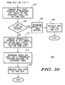
- step 122 it is determined that all received octets, v(n), are not odd, then in step 126 it is determined if all received octets, v(n), are even, i.e. it is determined whether there have been no odd v(n) octets received, such as in IDT table 70, FIG. 6A . If all received octets, v(n), are even, then in step 128 it is indicated that RBS2 is "1" or odd RBS for that time slot. If in step 126 it is determined that all received octets, v(n), are not even, then in step 130 it is indicated that there is no RBS2 in the digital network for that time slot.
- step 108 digital loss in the network is detected, as more fully described in FIG. 9 .
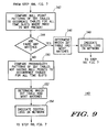
- Flow diagram 140, FIG. 9 depicts digital loss detection according to this invention.
- the null point patterns i.e. the locations of the null points
- the null point patterns i.e. the locations of the null points
- the IDT tables and time slots with no RBS2 are used in order to ensure more reliable digital loss detection. Also, since digital loss does not vary from time slot to time slot, the comparisons are made across time slots to ensure more accurate digital loss detection.
- the IDT tables for (i) and (iv) do not have any null points (except for several large ⁇ -law octets in case of iv), therefore, these IDT tables are not compared to the occurrence tables.
- step 144 it is determined if there are any null point pattern matches between the IDT tables and the occurrence tables. For example, if an occurrence table for a particular time slot has zero occurrences at each of the null points of the IDT table for case (v), the digital loss in the network at that time slot will be determined to be 6dB digital loss, the digital loss for case (v).
- the null pattern of each of the possible IDT tables is compared to the occurrence tables associated with each of the time slots having no RBS2.
- step 146 it is determined which IDT table had the most matches and in step 148 the type of digital loss associated with the IDT table having the most matches is indicated to be the type of digital loss present in the network for all time slots.
- step 150 probability patterns of all the IDT tables not having null points are compared to the occurrence tables for each time slot.
- there are only two IDT tables not having null points namely, the IDT tables of cases (i) and (iv) (except for several large ⁇ -law octets in case of iv).
- the probabilities of some entries of v(n) in the IDT tables are determined and compared to the occurrence tables to check for similar probability patterns.
- the IDT tables 80, FIG. 6B , and 90, FIG. 6C are the IDT tables for cases (i) and (iv), respectively.
- IDT table 80 0dB digital loss
- IDT table 90 6dB digital loss
- Other v(n) octets having similar properties may also be used.
- step 152 it is determined which IDT table had the most matches across time slots and in step 154 the digital loss associated with the IDT table having the most probability pattern matches is the indicated to be the type of digital loss present in the digital network.
- RBS1 is detected in step 110.
- the analog channel, c(n) can be estimated taking into account the determined upstream digital impairments.
- PCM upstream transmission can be modeled as in FIG. 11 .
- FIG. 11 there is shown the upstream transmission block diagram 20' of FIG. 3 without PCM downstream echo.
- the analog channel, c(n) can be estimated in half duplex mode, i.e., when digital modem 38' does not transmit downstream and therefore there is no PCM downstream echo in the upstream transmission.
- PCM upstream transmsmissio can be modeled as in FIG. 4 and c(n) can be estimated in full duplex mode.
- the estimation of c(n) in half duplex mode will first be described. The estimation of c(n), together with the estimation of echo(n) in full duplex mode are described below with regard to FIG. 16 .
- Analog channel estimator 200 is implemented in digital modem 38'.
- Analog channel estimator 200 includes analog channel estimation block 202 which is implemented as an FIR filter and which receives as inputs the reference directed training sequence z(n) and an error signal, error(n), and outputs a signal y(n)', an estimation of y(n).
- Signal y(n)' is input to a ⁇ -law quantization block 204 which quantizes signal y(n)' to form signal q(n)'.
- the signal q(n)' is provided to US RBS1 block 206, US digital loss block 208 and US RBS2 block 210, which modify the signal according to the detected digital impairments to produce a signal v(n)', an estimation of received signal v(n).
- US RBS1 and RBS2 may vary according to time slot and before they are determined it assumed that they are not present.
- Signal v(n)' is provided to octet to linear converter 211 which converts octets, v(n)' to linear values, vl(n)'.
- the linear values, vl(n)' are provided to adder 212.
- the actual received octets, v(n) are provided to octet to linear converter 213 which converts octets v(n) to linear values vl(n).
- the linear values vl(n) are also provided to adder 212 where the difference between vl(n) and vl(n)' is taken and provided as the error signal, error(n), to analog channel estimation block 202.
- Analog channel estimation block 202 uses the reference directed training sequence z(n), the error signal, error(n), and a least means square (LMS) algorithm, estimates the analog channel characteristic, c(n), as follows.
- LMS algorithm see, e.g., B. Widrow and S. D. Stems, "Adaptive Signal Processing", Prentice Hall, Inc., Englewood Cliffs, N.J. 1985 .
- Digital modem 38' then transmits the coefficients of the analog channel, c(n), to analog modem 22' which uses this information to improve upstream transmission, as described in co-pending application US Apl. Ser. No. 08/994,254 .
- the PCM downstream echo, echo(n), can be estimated according to this invention by using echo estimator 220, FIG. 13 , implemented within digital modem 38'.
- Echo estimator 220 takes into account both downstream and upstream digital impairments, as described below.
- the downstream echo, echo(n), being estimated is the echo introduced into the upstream transmission at the input of ⁇ -law quantizer 34' , FIG. 4 .
- Echo estimator 220 includes an inverse virtual quantizer block 222 which receives signal v(n) and outputs virtual quantizer points, vq(n).
- the ⁇ -law quantizer 34' and the detected upstream digital impairments are modeled as an equivalent new quantizer, inverse virtual quantizer 222, by setting equivalent quantizer thresholds as required given the detected impairments.
- An example of this is depicted in FIGS. 14 and 15 . It should be noted that to estimate echo(n) most precisely the upstream portion of echo estimator 220 should be modeled as in FIG. 4 with the ⁇ -law quantizer and the upstream impairment blocks, but since this is not feasible as q(n) is not known even though v(n) is given, inverse virtual quantizer 222 is used as the best alternative.
- echo estimator 220 also includes DS RBS1 block 224, which receives the downstream PCM signal, s(n). This signal also passes through DS digital loss block 226 and DS RBS2 block 228 which outputs a digitally impaired transmitted signal to octet to linear converter 229 which converts the octets p(n) to ⁇ -law linear values pl(n).
- the ⁇ -law linear values pl(n) are provided to echo channel block 230, which is implemented as an FIR filter.
- the digital impairment blocks are designed according to the digital impairments detected by analog modem 22'.
- the output of echo channel block 230 is the PCM downstream echo, echo(n), which is provided to adder 232.
- the virtual quantizer points, vq(n) are also supplied to adder 232 which takes the difference between vq(n) and echo(n) to form the error signal, error(n) that is fed back to echo channel block 230.
- the echo variance, ⁇ c 2 can be obtained by averaging the squared values of echo(n) over a predetermined time period, for example 1000 symbol times.
- Digital modem 38' then transmits to analog modem 22' the echo variance and the analog modem uses this information to improve upstream transmission as described in co-pending application US Apl. Ser. No. 08/994,254 .
- digital modem 38' uses the echo(n) estimation in the decoder also as described in co-pending application US Apl. Ser. No. 08/994,254 .
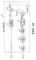
- Analog channel estimator 200a is configured the same as analog channel estimator 200, FIG. 12 , except that there is a PCM downstream echo component, echo(n), estimated by echo estimator 220a, added to the output of analog channel estimation block 202a.
- Echo estimator 220a is configured the same as echo estimator 220, FIG. 13 , except that there is no inverse virtual quatizer. Also, the estimators use a common error signal, error(n).
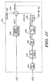
- the PCM downstream echo, echo(n), can be estimated even more precisely according to this invention by using enhaced echo estimator 220b, FIG. 17 , implemented within digital modem 38'.
- Echo estimator 220b includes an inverse virtual quantizer block 222b which receives signal v(n) and outputs virtual quantizer points, vq(n).
- the ⁇ -law quantizer 34', FIG. 3 , and the detected upstream digital impairments are modeled as an equivalent new quantizer, inverse virtual quantizer 222b, by setting equivalent quantizer thresholds as required given the detected impairments, as described above.
- Enhanced echo estimator 220b also includes DS RBS1 block 224b, which receives the downstream PCM signal, s(n). This signal also passes through DS digital loss block 226b and DS RBS2 block 228b which outputs a digitally impaired transmitted signal p(n) to octet to linear converter 229b which converts the octets p(n) to ⁇ -law linear values pl(n).
- the ⁇ -law linear values pl(n) are provided to echo channel block 230b, which is implemented as an FIR filter.
- the digital impairment blocks are designed according to the digital impairments detected by analog modem 22'.
- the output of echo channel block 230b is the PCM downstream echo, echo(n), which is provided to adder 232b.
- the virtual quantizer points vq(n) and the points y(n), which the digital modem 38'decodes from v(n) before determining u(n), are also supplied to adder 232b.
- Adder 232b sums vq(n), y(n) and echo(n) (vq(n) is positive and y(n) and echo(n) are negative) to form the error signal, error(n), (analog channel error signal) that is fed back to echo channel block 230b.
- error(n) is also transmitted to the analog PCM modem for adapting a target response p(n) and prefilter g(n), as described in co-pending US application serial No. 09/092,482 , filed on even date herewith.
- the more frequently the error signal is transmitted to the analog PCM modem the better the adaptation will be; however, it will be at the expense of data rate. It is possible to transmit with every symbol only the sign of the error signal and use it for adaptation without sacrificing too much of the downstream data rate.
- Echo channel block 230b using the digitally impaired signal pl(n), the error signal, error(n), and a least means square algorithm, estimates the PCM downstream echo, echo(n), by adapting h(n) as described above with regard to equation (3). Since h(n) is adapted using the error signal uncorrupted by the upstream signal y(n), the adaptation is faster.
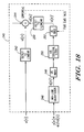
- Error signal generator 240 includes an octet to linear converter 242 that converts v(n) to vl(n) which is provided to adder 244. There is also included a ⁇ -law quantizer 246 which receives the decoded values y(n) affected by the estimated echo, echo(n), and outputs octets q(n)'. The octets are then modified by US RBS1 block 248, US digital loss block 250 and US RBS2 block 252 to form octets v(n)'.
- Octets v(n)' are then provided to octet to linear converter 254 which outputs vl(n)'to adder 244.
- Adder 254 sums vl(n) and vl(n)'and outputs the error signal, error(n) or e(n).
- this invention may be embodied in software and/or firmware which may be stored on a computer useable medium, such as a computer disk or memory chip.
- the invention may also take the form of a computer data signal embodied in a carrier wave, such as when the invention is embodied in software/firmware which is electrically transmitted, for example, over the Internet.
Landscapes
- Computer Networks & Wireless Communication (AREA)
- Signal Processing (AREA)
- Engineering & Computer Science (AREA)
- Physics & Mathematics (AREA)
- Spectroscopy & Molecular Physics (AREA)
- Electromagnetism (AREA)
- Telephonic Communication Services (AREA)
- Maintenance And Management Of Digital Transmission (AREA)
- Cable Transmission Systems, Equalization Of Radio And Reduction Of Echo (AREA)
- Monitoring And Testing Of Exchanges (AREA)
- Data Exchanges In Wide-Area Networks (AREA)
- Detection And Prevention Of Errors In Transmission (AREA)
- Time-Division Multiplex Systems (AREA)
- Dc Digital Transmission (AREA)
- Transmission Systems Not Characterized By The Medium Used For Transmission (AREA)
- Monitoring And Testing Of Transmission In General (AREA)
Claims (35)
- Verfahren zur Detektion von digitalen Fehlern, die einen zuvor entstandenen Pulscodemodulations-, PCM-Kanal in einem digitalen Kommunikationsnetz betreffen, umfassend;
Empfang (102), durch ein digitales PCM-Modem, das mit dem digitalen Kommunikationsnetz verbunden ist, einer zufälligen Sequenz von digitalen Werten, ausgewählt aus einer Konstellation von digitalen Werten, die über den zuvor entstandenen PCM-Kanal des digitalen Kommunikationsnetzes übertragen werden;
Festsetzung (104) der Verteilungen der empfangenen digitalen werte, wobei jede Verteilung einem einer Vielzahl von zeitintervallen entspricht; und
Ableitung (106, 108, 110) von den Verteilungen der Arten von Robbed-Bit-Signalisierung und digitalem Verlust, die den zuvor entstandenen PCM-Kanal des digitalen Kommunikationsnetzes für jedes Zeitintervall betreffen. - Verfahren nach Anspruch 1, wobei der Schritt des Festsetzens (104) die Festsetzung von Vorkommenstabellen für die Konstellation von digitalen Werten von der erhaltenen zufälligen Sequenz durch die Aufrechterhaltung einer Häufigkeit der Anzahl von Malen, die jeder der digitalen Werte in der Konstellation durch das digitale PCM-Modem während jedes Zeitintervalls empfangen wird, umfasst.
- Verfahren nach Anspruch 2, wobei ein erstes Vorkommen von Robbed-Bit-Signalisierung vor dem digitalen Verlust und ein zweites Vorkommen von Robbed-Bit-Signalisierung nach dem digitalen Verlust vorhanden ist.
- Verfahren nach Anspruch 3, wobei der Schritt des Ableitens (106, 108, 110) die Beobachtung der am wenigsten signifikanten Bits der empfangenen digitalen Werte in den Verteilungen umfasst, um die Art des zweiten Vorkommens von Robbed-Bit-Signalisierung in jedem Zeitintervall zu bestimmen.
- Verfahren nach Anspruch 4, wobei der Schritt des Ableitens (106, 108, 110) weiter den Vergleich einer Vielzahl von Fehlertabellen, die verschiedenen Kombinationen des ersten und des zweiten Vorkommens von Robbed-Bit-Signalisierung und digitalem Verlust entsprechen, mit den Vorkommenstabellen umfasst, um die Art von digitalem Verlust zu bestimmen, der den zuvor entstandenen PCM-Kanal des digitalen Kommunikationsnetzes betrifft.
- Verfahren nach Anspruch 5, wobei der Schritt des Vergleichens den Vergleich eines Musters jeder der Fehlertabellen mit den Vorkommenstabellen umfasst.
- Verfahren nach Anspruch 6, wobei der Schritt des Vergleichens weiter die Bestimmung umfasst, welche Fehlertabellen null Punkte aufweisen, und den Vergleich der Null-Punkt-Muster der Fehlertabellen mit null Punkten mit den Vorkommenstabellen, und die Bestimmung, ob eines der Null-Punkt-Muster zu den Vorkommenstabellen passt, wodurch angegeben wird, dass die Art von digitalem Verlust, die mit der passenden Fehlertabelle assoziiert ist, die Art von digitalem Verlust ist, die das digitale Netz betrifft.
- Verfahren nach Anspruch 7, wobei der Schritt des Vergleichens weiter den Vergleich, wenn keine Null-Punkt-Muster passen, der Wahrscheinlichkeitsmuster der Fehlertabellen, die nicht null Punkte aufweisen, und die Bestimmung, welches Wahrscheinlichkeitsmuster zur Vorkommenstabelle passt, umfasst, wodurch angegeben wird, dass die Art von digitalem Verlust, der mit der passenden Fehlertabelle assoziiert ist, die Art von digitalem Verlust ist, die das digitale Netz betrifft.
- Verfahren nach Anspruch 8, wobei der Schritt des Ableitens (106, 108, 110) weiter den Vergleich einer Vielzahl von Fehlertabellen, die verschiedenen Kombinationen des ersten und des zweiten Vorkommens von Robbed-sit-Signalisierung und digitalem Verlust entsprechen, mit den Vorkommenstabellen umfasst, um die Art des ersten Vorkommens von Robbed-Bit-Signalisierung zu bestimmen, die den zuvor entstandenen PCM-Kanal des digitalen Kommunikationsnetzes für jedes Zeitintervall betrifft.
- Verfahren nach Anspruch 9, wobei der Schritt des Vergleichens den Vergleich eines Musters jeder der Fehlertabellen mit den Vorkommenstabellen umfasst.
- Verfahren nach Anspruch 10, wobei der Schritt des Vergleichens weiter die Bestimmung umfasst, welche Fehlertabellen null Punkte aufweisen, und den vergleich der Null-Punkt-Muster der Fehlertabellen mit null Punkten mit den Vorkommenstabellen und die Bestimmung, ob eines der Null-Punkt-Muster zu den Vorkommenstabellen passt, wodurch angegeben wird, dass die Art des ersten Vorkommens von Robbed-Bit-Signalisierung, die mit der passenden Fehlertabelle assoziiert ist, die Art des ersten Vorkommens von Robbed-Bit-Signalisierung ist, die das digitale Netz für jedes Zeitintervall betrifft.
- Verfahren nach Anspruch 11, wobei der Schritt des Vergleichens weiter den Vergleich, wenn keine Null-Punkt-Muster passen, der Wahrscheinlichkeitsmuster der Fehlertabellen, die nicht null Punkte aufweisen, und die Bestimmung, welches Wahrscheinlichkeitsmuster zur Vorkommenstabelle passt, umfasst, wodurch angegeben wird, dass die Art des ersten Vorkommens von Robbed-Bit-Signalisierung, die mit der passenden Fehlertabelle assoziiert ist, die Art des ersten Vorkommens von Robbed-Bit-Signalisierung ist, die das digitale Netz für jedes Zeitintervall betrifft.
- Verfahren nach Anspruch 1, wobei die Vielzahl von Zeitintervallen Robbed-Bit-Signalisierungs-Zeitintervalle sind.
- Verfahren nach Anspruch 2, wobei der Schritt des Ableitens (106, 108, 110) die Beseitigung bestimmter Arten von Robbed-Bit-Signalisierung und digitalem Verlust als mögliche Arten umfasst, die das digitale Kommunikationsnetz betreffen, wenn digitale Werte empfangen werden, die einen vorbestimmten Wert übersteigen.
- Verfahren zur Schätzung der Koeffizienten eines analogen Kanals (200) in einer Anordnung, in der ein digitales Pulscodemodulations-, PCM-Modem mit einem digitalen Kommunikationsnetz verbunden und dazu ausgelegt ist, eine Datenübertragung von einem analogen PCM-Modem zu empfangen, und in dem die analoge PCM mit dem analogen Kanal verbunden ist, wobei das Verfahren Folgendes umfasst:Empfang, durch das digitale PCM-Modem, einer Sequenz von Oktetten, v(n), vom zuvor entstandenen PCM-Kanal des digitalen Kommunikationsnetzes, wobei die Oktette aus einer Sequenz von Ebenen erzeugt sind, die vom analogen PCM-Modem über den analogen Kanal übertragen und quantisiert werden,Bestimmung, von den erhaltenen Oktetten, der digitalen Fehler, die den zuvor entstandenen PCM-Kanal des digitalen Kommunikationsnetzes betreffen, wobei die digitalen Fehler unter Verwendung des Verfahrens von einem der Ansprüche 1 bis 14 nachgewiesen werden;Umwandlung der empfangenen Oktette zu empfangenen linearen Werten, vl(n);Empfang einer zufälligen Referenz-gerichteten Trainingssequenz der Ebenen, die vom analogen PCM-Modem übertragen werden, wobei die zufällige Referenz-gerichtete Trainingssequenz eine ist, die Signale mit einer im Wesentlichen Gauß'schen Verteilung erzeugt;Filterung der Referenz-gerichteten Sequenz mit einem analogen kanalfilter mit analogen Kanalkoeffizienten, um eine gefilterte Referenz-gerichtete Sequenz zu erzeugen:Quantisierung der gefilterten Referenz-gerichteten Sequenz, um eine Sequenz von Referenz-gerichteten Oktetten zu erzeugen;Modifizierung der Sequenz von Referenz-gerichteten Oktetten gemäß den festgesetzten zuvor entstandenen digitalen Fehlern, um eine geschätzte Sequenz von Oktetten, v(n)', zu erzeugen, wobei es sich um eine Schätzung der Sequenz von erhaltenen Oktetten, v(n), handelt;Umwandlung der geschätzten Sequenz von Oktetten, v(n)' zu geschätzten linearen Werten, vl(n)';Erzeugung eines Fehlersignals durch die Verwendung des Unterschieds zwischen den empfangenen linearen werten, (vl)n) und den geschätzten linearen Werten, vl(n)'; undSchätzung der analogen Kanalkoeffizienten unter Verwendung des Fehlersignals und der Referenz-gerichteten Sequenz der Ebenen.
- Verfahren nach Anspruch 15, wobei das Verfahren weiter dazu dient, das danach entstandene Echo (220) zu schätzen, eingeführt in die zuvor entstandene Datenübertragung bei der Eingabe einer Quantisierungsvorrichtung, hervorgerufen durch die danach entstandene Datenübertragung vom digitalen PCM-Modem an das analoge PCM-Modem; wobei das Verfahren weiter Folgendes umfasst:Zugabe eines geschätzten danach entstandenen Echos an die gefilterte Referenz-gerichtete Sequenz;Modifizierung der Oktette, die nachgelagert vom digitalen PCM-Modem übertragen werden, gemäß vorbestimmten danach entstandenen digitalen Fehlern, um modifizierte danach entstandene Oktette, p(n), zu erzeugen;Umwandlung der modifizierten danach entstandenen Oktette zu modifizierten danach entstandenen linearen Werten pl(n);Filterung der modifizierten danach entstandenen linearen Werte, pl(n), mit einem danach entstandenen Echokanalfilter, der Echokanalkoeffizienten aufweist, um ein geschätztes danach entstandenes Echo zu erzeugen; und Aktualisierung der Echokanalkoeffizienten unter Verwendung des Fehlersignals und der modifizierten danach entstandenen linearen Werte, pl(n).
- Verfahren zu Schätzung des danach entstandenen Echos (220), eingeführt in eine zuvor entstandene Datenübertragung bei der Eingabe einer Quantisierungsvorrichtung, hervorgerufen durch die danach entstandene Datenübertragung von einem digitalen Pulscodemodulations-, PCM-Modem an das analoge PCM-Modem; in einer Anordnung, in der das digitale PCM-Modem mit einem digitalen Kommunikationsnetz verbunden und dazu ausgelegt ist, eine zuvor entstandene Datenübertragung vom analogen PCM-Modem zu empfangen, und in dem das analoge PCM-Modem mit dem analogen Kanal verbunden ist; wobei das Verfahren Folgendes umfasst:Empfang, durch das digitale PCM-Modem, einer Sequenz von Oktetten, v(n),vom zuvor entstandenen PCM-Kanal des digitalen Kommunikationsnetzes, wobei die Oktette aus einer Sequenz von Ebenen erzeugt sind, die vom analogen PCM-Modem über den analogen Kanal übertragen und von der Quantisierungsvorrichtung quantisiert werden;Bestimmung, von den erhaltenen Oktetten, der digitalen Fehler, die den zuvor entstandenen PCM-Kanal des digitalen Kommunikationsnetzes betreffen, wobei die digitalen Fehler unter Verwendung des Verfahrens eines der Ansprüche 1 bis 14 nachgewiesen werden;Dekodierung der empfangenen Oktette;Umwandlung der empfangenen Oktette, basierend auf der Quantisierungsvorrichtung und den festgelegten zuvor entstandenen digitalen Fehlern, zu virtuellen Quantisiererpunkten, vq(n);Modifizierung der Oktette, nachgelagert übertragen vom digitalen PCM-Modem gemäß vorbestimmten danach entstandenen digitalen Fehler, um modifizierte danach entstandene Oktette, p(n), zu erzeugen;Umwandlung der modifizierten danach entstandene Oktette zu modifizierten danach entstandenen linearen Werten pl(n);Filterung der modifizierten danach entstandenen linearen werte, pl(n), mit einem danach entstandenen Echokanalfilter, der Echokanalkoeffizienten aufweist, um eine danach entstandene Echoschätzung zu erzeugen;Erzeugung eines Fehlersignals durch die Verwendung des Unterschieds zwischen den virtuellen Quantisiererpunkten, vq(n), dem geschätzten danach entstandenen Echo und den dekodierten empfangenen Oktetten; und Aktualisierung der Echokanalkoeffizienten unter Verwendung des Fehlersignals und der modifizierten danach entstandenen linearen Werte, pl(n).
- Verfahren zur Detektion von digitalen Fehlern, die einen zuvor entstandenen Pulscodemodulations-, PCM-Kanal in einem digitalen Kommunikationsnetz betreffen, umfassend;
Logik zum Empfang (102), durch ein digitales PCM-Modem, das mit dem digitalen Kommunikationsnetz verbunden ist, einer zufälligen Sequenz von digitalen Werten, ausgewählt aus einer Konstellation von digitalen Werten, die über den zuvor entstandenen PCM-Kanal des digitalen Kommunikationsnetzes übertragen werden;
Logik für die Festsetzung (104) der Verteilungen der empfangenen digitalen werte, wobei jede Verteilung einem einer Vielzahl von Zeitintervallen entspricht; und
Logik für die Ableitung (106, 108, 110) von den Verteilungen der Arten von Robbed-Bit-Signalisierung und digitalem Verlust, die den zuvor entstandenen PCM-Kanal des digitalen Kommunikationsnetzes für jedes Zeitintervall betreffen. - Vorrichtung nach Anspruch 18, wobei die Logik für die Festsetzung (104) eine Logik für die Festsetzung von vorkommenstabellen für die Konstellation von digitalen Werten von der erhaltenen zufälligen Sequenz durch die Aufrechterhaltung einer Häufigkeit der Anzahl von Malen, die jeder der digitalen Werte in der Konstellation durch das digitale PCM-Modem während jedes Zeitintervalls empfangen wird, umfasst.
- Vorrichtung nach Anspruch 19, wobei ein erstes Vorkommen von Robbed-Bit-Signalisierung vor dem digitalen Verlust und ein zweites Vorkommen von Robbed-Bit-Signalisierung nach dem digitalen Verlust vorhanden ist.
- Vorrichtung nach Anspruch 20, wobei die Logik für die Ableitung (106, 108, 110) die Logik für die Beobachtung der am wenigsten signifikanten Bits der empfangenen digitalen Werte in den Verteilungen umfasst, um die Art des zweiten Vorkommens von Robbed-Bit-Signalisierung in jedem Zeitintervall zu bestimmen.
- Vorrichtung nach Anspruch 21, wobei die Logik für die Ableitung (106, 108, 110) weiter die Logik für den Vergleich einer Vielzahl von Fehlertabellen, die verschiedenen Kombinationen des ersten und des zweiten Vorkommens von Robbed-Bit-Signalisierung und digitalem Verlust entsprechen, mit den Vorkommenstabellen umfasst, um die Art von digitalem Verlusts zu bestimmen, die den zuvor entstandenen PCM-Kanal des digitalen Kommunikationsnetzes betrifft.
- Vorrichtung nach Anspruch 22, wobei die Logik für den Vergleich die Logik für den Vergleich eines Musters jeder der Fehlertabellen mit den Vorkommenstabellen umfasst.
- Vorrichtung nach Anspruch 23, wobei die Logik für den Vergleich weiter eine Logik für die Bestimmung umfasst, welche Fehlertabellen null Punkte aufweisen, und Logik für den Vergleich des Null-Punkt-Musters der Fehlertabellen mit null Punkten mit den Vorkommenstabellen und die Bestimmung, ob eines der Null-Punkt-Muster zu den Vorkommenstabellen passt, wodurch angegeben wird, dass die Art von digitalem Verlust, die mit der passenden Fehlertabelle assoziiert ist, die Art von digitalem Verlust ist, die das digitale Netz betrifft.
- Vorrichtung nach Anspruch 24, wobei die Logik für den Vergleich weiter die Logik für den Vergleich, wenn keine Null-Punkt-Muster passen, der Wahrscheinlichkeitsmuster der Fehlertabellen, die nicht null Punkte aufweisen, und die Bestimmung, welches Wahrscheinlichkeitsmuster zur Vorkommenstabelle passt, umfasst, wodurch angegeben wird, dass die Art von digitalem Verlust, die mit der passenden Fehlertabelle assoziiert ist, die Art von digitalem Verlust ist, die das digitale Netz betrifft.
- Vorrichtung nach Anspruch 25, wobei die Logik für die Ableitung (106, 108, 110) weiter die Logik für den Vergleich einer Vielzahl von Fehlertabellen, die verschiedenen Kombinationen des ersten und des zweiten Vorkommens von Robbed-Bit-Signalisierung und digitalem Verlust entsprechen, mit den Vorkommenstabellen umfasst, um die Art des ersten Vorkommens von Robbed-Bit-Signalisierung zu bestimmen, die den zuvor entstandenen PCM-Kanal des digitalen Kommunikationsnetzes für jedes Zeitintervall betrifft.
- Vorrichtung nach Anspruch 26, wobei die Logik für den Vergleich die Logik für den Vergleich eines Musters jeder der Fehlertabelle mit den Vorkommenstabellen umfasst.
- Vorrichtung nach Anspruch 27, wobei die Logik für den Vergleich weiter Logik für die Bestimmung umfasst, welche Fehlertabellen null Punkte aufweisen, und Logik für den Vergleich der Null-Punkt-Muster der Fehlertabellen mit null Punkten mit den Vorkommenstabellen und die Bestimmung, ob eines der Null-Punkt-Muster zu den Vorkommenstabellen passt, wodurch angegeben wird, dass die Art des ersten Vorkommens von Robbed-Bit-Signalisierung, die mit der passenden Fehlertabelle assoziiert ist, die Art des ersten Vorkommens von Robbed-Bit-Signalisierung ist, die das digitale Netz für jedes Zeitintervall betrifft.
- Vorrichtung nach Anspruch 28, wobei die Logik für den Vergleich weiter die Logik für den Vergleich, wenn keine Null-Punkt-Muster passen, der Wahrscheinlichkeitsmuster der Fehlertabellen, die nicht null Punkte aufweisen, und die Logik für die Bestimmung, welches Wahrscheinlichkeitsmuster zur Vorkommenstabelle passt, umfasst, wodurch angegeben wird, dass die Art des ersten Vorkommens von Robbed-Bit-Signalisierung, die mit der passenden Fehlertabelle assoziiert ist, die Art des ersten Vorkommens von Robbed-Bit-Signalisierung ist, die das digitale Netz für jedes Zeitintervall betrifft.
- Vorrichtung nach Anspruch 18, wobei die Vielzahl von zeitintervallen Robbed-Bit-Signalisierungs-Zeitintervalle sind.
- Vorrichtung nach Anspruch 19, wobei die Logik für die Ableitung (106, 108, 110) Logik für die Beseitigung bestimmter Arten von Robbed-Bit-Signalisierung und digitalem Verlust als mögliche Arten umfasst, die das digitale Kommunikationsnetze betreffen, wenn digitale Werte empfangen werden, die einen vorbestimmten Wert übersteigen.
- Vorrichtung zur Schätzung der Koeffizienten eines analogen Kanals (200), wobei die Vorrichtung zur Verwendung in einer Anordnung ist, in der das digitale Pulscodemodulations-, PCM-Modem mit einem digitalen Kommunikationsnetz verbunden und dazu ausgelegt ist, eine Datenübertragung von einem analogen PCM-Modem zu empfangen, das mit dem analogen Kanal verbunden ist; wobei die Vorrichtung Folgendes umfasst:Logik für den Empfang, durch das digitale PCM-Modem, einer Sequenz von Oktetten, v(n), vom zuvor entstandenen PCM-Kanal des digitalen Kommunikationsnetzes, wobei die Oktette aus einer Sequenz von Ebenen erzeugt sind, die vom analogen PCM-Modem über den analogen Kanal übertragen und quantisiert werden,Logik für die Bestimmung, von den erhaltenen Oktetten, der digitalen Fehler, die den zuvor entstandenen PCM-Kanal des digitalen Kommunikationsnetzes betreffen, wobei die digitalen Fehler unter Verwendung der Vorrichtung von einem der Ansprüche 18 bis 31 nachgewiesen werden;Logik für die Umwandlung der empfangenen Oktette zu empfangenen linearen Werten, vl(n);Logik zum Empfang einer zufälligen Referenz-gerichteten Trainingssequenz der Ebenen, die vom analogen PCM-Modem übertragen werden, wobei die zufällige Referenz-gerichtete Trainingssequenz eine ist, die Signale mit einer im Wesentlichen Gauß'schen Verteilung erzeugt;Logik für die Filterung der Referenz-gerichteten Sequenz mit einem analogen Kanalfilter mit analogen Kanalkoeffizienten, um eine gefilterte Referenz-gerichtete Sequenz zu erzeugen;Logik für die Quantisierung der gefilterten Referenz-gerichteten Sequenz, um eine Sequenz von Referenz-gerichteten Oktetten zu erzeugen;Logik für die Modifizierung der Sequenz von Referenz-gerichteten Oktetten gemäß den festgesetzten zuvor entstandenen digitalen Fehlern, um eine geschätzte Sequenz von Oktetten, v(n)', zu erzeugen, wobei es sich um eine Schätzung der Sequenz von erhaltenen Oktetten, v(n), handelt;Logik für die Umwandlung der geschätzten Sequenz von Oktetten, v(n)' zu geschätzten linearen Werten, vl(n)';Logik für die Erzeugung eines Fehlersignals durch die Verwendung des Unterschieds zwischen den empfangenen linearen Werten, vl(n), und den geschätzten linearen Werten, vl(n)'; undLogik für die Schätzung der analogen Kanalkoeffizienten unter Verwendung des Fehlersignals und der Referenz-gerichteten Sequenz der Ebenen.
- Verfahren zu Schätzung des danach entstandenen Echos (220), eingeführt in die zuvor entstandene Datenübertragung bei der Eingabe einer Quantisierungsvorrichtung, hervorgerufen durch die danach entstandene Datenübertragung von einem digitalen Pulscodemodulations-, PCM-Modem an ein analoges PCM-Modem; wobei die Vorrichtung zur Verwendung in einer Anordnung ist, in der das digitale PCM-Modem mit dem digitalen Kommunikationsnetz verbunden und dazu ausgelegt ist, eine zuvor entstandene Datenübertragung vom analogen PCM-Modem zu empfangen, und in dem das analoge PCM-Modem mit dem analogen Kanal verbunden ist, wobei das Verfahren Folgendes umfasst:Logik für den Empfang, durch das digitale PCM-Modem, einer Sequenz von Oktetten, v(n), vom zuvor entstandenen PCM-Kanal des digitalen Kommunikationsnetzes, wobei die Oktette aus einer Sequenz von Ebenen erzeugt sind, die vom analogen PCM-Modem über den analogen Kanal übertragen und von der Quantisierungsvorrichtung quantisiert werden;Logik für die Bestimmung von den erhaltenen Oktetten der digitalen Fehler, die den zuvor entstandenen PCM-Kanal des digitalen Kommunikationsnetzes betreffen, wobei die digitalen Fehler unter Verwendung der Vorrichtung von einem der Ansprüche 18 bis 31 nachwiesen werden;Logik für die Dekodierung der empfangenen Oktette;Logik für die Umwandlung der empfangenen Oktette, basierend auf der Quantisierungsvorrichtung und den festgelegten zuvor entstandenen digitalen Fehlern, zu virtuellen Quantisiererpunkten, vq(n);Logik für die Modifizierung der Oktette, die nachgelagert vom digitalen PCM-Modem übertragen werden, gemäß vorbestimmten danach entstandenen digitalen Fehlern, um modifizierte danach entstandene Oktette, p(n), zu erzeugen;Logik für die Umwandlung der modifizierten danach entstandenen Oktette zu modifizierten danach entstandenen linearen Werten pl(n);Logik für die Filterung der modifizierten danach entstandenen linearen Werte, pl(n), mit einem danach entstandenen Echokanalfilter, der Echokanalkoeffizienten aufweist, um eine danach entstandene Echoschätzung zu erzeugen;Logik für die Erzeugung eines Fehlersignals durch die Verwendung des Unterschieds zwischen den virtuellen Quantisiererpunkten, vq(n), dem geschätzten danach entstandenen Echo und den dekodierten empfangenen Oktetten; und Logik für die Aktualisierung der Echokanalkoeffizienten unter Verwendung des Fehlersignals und der modifizierten danach entstandenen linearen Werte, pl(n).
- Computer-verwendbares Medium mit Computerlesbaren Programmcodemitteln, die darin enthalten sind, um das Verfahren von einem der Ansprüche 1 bis 17 durchzuführen.
- Computer-Datensignal, das in einer Trägerwelle enthalten ist, wobei im Computer-Datensignal Computerlesbare Programmcodemittel enthalten sind, um das Verfahren von einem der Ansprüche 1 bis 17 durchzuführen.
Applications Claiming Priority (5)
| Application Number | Priority Date | Filing Date | Title |
|---|---|---|---|
| US92786 | 1979-11-08 | ||
| US999416 | 1992-12-31 | ||
| US08/999,416 US6181752B1 (en) | 1997-12-29 | 1997-12-29 | Device and method for detecting PCM upstream digital impairments in a communication network |
| US09/092,786 US6201842B1 (en) | 1997-12-29 | 1998-06-05 | Device and method for detecting PCM upstream digital impairments in a communication network |
| PCT/US1998/024734 WO1999034504A1 (en) | 1997-12-29 | 1998-11-19 | Device and method for detecting pcm upstream digital impairments in a communication network |
Publications (3)
| Publication Number | Publication Date |
|---|---|
| EP1042861A1 EP1042861A1 (de) | 2000-10-11 |
| EP1042861A4 EP1042861A4 (de) | 2004-07-21 |
| EP1042861B1 true EP1042861B1 (de) | 2013-03-27 |
Family
ID=26786052
Family Applications (1)
| Application Number | Title | Priority Date | Filing Date |
|---|---|---|---|
| EP98959517A Expired - Lifetime EP1042861B1 (de) | 1997-12-29 | 1998-11-19 | Vorrichtung und verfahren zur detektion von zuvor entstandenen digitalen pcm-fehlern in einem kommunikationsnetz |
Country Status (9)
| Country | Link |
|---|---|
| US (1) | US6201842B1 (de) |
| EP (1) | EP1042861B1 (de) |
| JP (1) | JP2002500458A (de) |
| KR (3) | KR100423855B1 (de) |
| CN (1) | CN1283325A (de) |
| AU (1) | AU1530199A (de) |
| BR (1) | BR9814537A (de) |
| CA (1) | CA2317554C (de) |
| WO (1) | WO1999034504A1 (de) |
Families Citing this family (18)
| Publication number | Priority date | Publication date | Assignee | Title |
|---|---|---|---|---|
| US6023493A (en) | 1998-01-20 | 2000-02-08 | Conexant Systems, Inc. | Method and apparatus for synchronizing a data communication system to a periodic digital impairment |
| US6643270B1 (en) * | 1998-03-03 | 2003-11-04 | Vocal Technologies, Ltd | Method of compensating for systemic impairments in a telecommunications network |
| US6366591B1 (en) * | 1998-07-13 | 2002-04-02 | Agere Systems Guardian Corp. | Technique for treating channel impairments involving measuring a digital loss in transmitted signals in data communications |
| US6185249B1 (en) * | 1999-01-28 | 2001-02-06 | Ic Tel Inc. | Translation table design for a PCM modem |
| US7190727B1 (en) | 1999-07-31 | 2007-03-13 | Broadcom Corporation | Categorization of impairments affecting a communication channel |
| US7203248B1 (en) | 1999-07-31 | 2007-04-10 | Broadcom Corporation | Impairment sensitive selection of constellation points for communication across a channel |
| AU6616500A (en) | 1999-07-31 | 2001-03-13 | Altocom, Inc. | Digital impairment compensation for v.90 modem |
| US6414989B1 (en) | 1999-09-10 | 2002-07-02 | Conexant Systems, Inc. | Upstream PCM transmission for a modem system |
| US6839382B1 (en) * | 1999-10-29 | 2005-01-04 | International Business Machines Corporation | System, methods and computer program products for identifying digital impairments in modem signals using signature analysis and signal level comparison analysis |
| US7085316B1 (en) * | 2000-02-04 | 2006-08-01 | General Electric Co. | Method and apparatus for the control of modem transmit power |
| US6266376B1 (en) * | 2000-02-04 | 2001-07-24 | Motorola, Inc. | System and method for adjusting PCM data frames for robbed bit signaling in a telephone network |
| US6418170B1 (en) * | 2000-02-07 | 2002-07-09 | Motorola, Inc. | Method and apparatus for achieving 180° phase invariant transmission in a PCM modem system |
| GB2365728A (en) * | 2000-03-22 | 2002-02-20 | Fernway Ltd | A method and apparatus for transmitting data from an analogue modem to a digital modem through an analogue channel |
| EP1224783A2 (de) * | 2000-04-06 | 2002-07-24 | Lucent Technologies Inc. | Aufwärtsdatenübertragung |
| US6987782B2 (en) * | 2001-04-06 | 2006-01-17 | Agere Systems, Inc. | Method and apparatus for detecting robbed bit location in PCM modems and the like |
| DE60238791D1 (de) * | 2002-03-20 | 2011-02-10 | Dounaev Igor Borisovich | Verfahren und systeme zur digitalen datenübertragung |
| US7321618B2 (en) * | 2002-04-09 | 2008-01-22 | Texas Instruments Incorporated | PCM upstream data transmission server |
| CN101908942B (zh) * | 2009-06-05 | 2014-10-08 | 华为技术有限公司 | 一种损伤信息传送方法、节点和网络系统 |
Family Cites Families (10)
| Publication number | Priority date | Publication date | Assignee | Title |
|---|---|---|---|---|
| US5388124A (en) * | 1992-06-12 | 1995-02-07 | University Of Maryland | Precoding scheme for transmitting data using optimally-shaped constellations over intersymbol-interference channels |
| US5394437A (en) | 1992-10-20 | 1995-02-28 | At&T Corp. | High-speed modem synchronized to a remote CODEC |
| US5546395A (en) * | 1993-01-08 | 1996-08-13 | Multi-Tech Systems, Inc. | Dynamic selection of compression rate for a voice compression algorithm in a voice over data modem |
| US5528625A (en) | 1994-01-03 | 1996-06-18 | At&T Corp. | High speed quantization-level-sampling modem with equalization arrangement |
| US5528679A (en) * | 1994-01-27 | 1996-06-18 | Primary Access Corporation | Automatic detection of digital call paths in a telephone system |
| US5757849A (en) * | 1995-03-30 | 1998-05-26 | Lucent Technologies Inc. | Timing recovery in a network-synchronized modem |
| US5784405A (en) * | 1996-08-23 | 1998-07-21 | Paradyne Corporation | Noncooperative feedback system and method for a compensation system associated with a transmitter or CODEC |
| US5754594A (en) * | 1996-08-23 | 1998-05-19 | Paradyne Corporation | Cooperative feedback system and method for a compensation system associated with a transmitter or codec |
| FR2753487B1 (fr) | 1996-09-19 | 1998-11-20 | Guy Negre | Installation de compresseurs d'alimentation en air comprime haute pression pour moteur depollue ou depolluant |
| US5875229A (en) * | 1996-10-15 | 1999-02-23 | Motorola Inc. | System and device for, and method of, detecting, characterizing, and mitigating deterministic distortion in a communications network |
-
1998
- 1998-06-05 US US09/092,786 patent/US6201842B1/en not_active Expired - Lifetime
- 1998-11-19 AU AU15301/99A patent/AU1530199A/en not_active Abandoned
- 1998-11-19 KR KR10-2002-7009042A patent/KR100423855B1/ko not_active Expired - Lifetime
- 1998-11-19 CA CA002317554A patent/CA2317554C/en not_active Expired - Lifetime
- 1998-11-19 BR BR9814537-1A patent/BR9814537A/pt not_active Application Discontinuation
- 1998-11-19 KR KR10-2000-7007215A patent/KR100383714B1/ko not_active Expired - Lifetime
- 1998-11-19 CN CN98812791A patent/CN1283325A/zh active Pending
- 1998-11-19 KR KR10-2002-7009043A patent/KR100422102B1/ko not_active Expired - Lifetime
- 1998-11-19 WO PCT/US1998/024734 patent/WO1999034504A1/en not_active Ceased
- 1998-11-19 JP JP2000527018A patent/JP2002500458A/ja active Pending
- 1998-11-19 EP EP98959517A patent/EP1042861B1/de not_active Expired - Lifetime
Also Published As
| Publication number | Publication date |
|---|---|
| EP1042861A1 (de) | 2000-10-11 |
| CN1283325A (zh) | 2001-02-07 |
| WO1999034504A1 (en) | 1999-07-08 |
| KR20010033692A (ko) | 2001-04-25 |
| JP2002500458A (ja) | 2002-01-08 |
| KR20020074198A (ko) | 2002-09-28 |
| CA2317554C (en) | 2003-08-05 |
| AU1530199A (en) | 1999-07-19 |
| KR100383714B1 (ko) | 2003-05-14 |
| US6201842B1 (en) | 2001-03-13 |
| EP1042861A4 (de) | 2004-07-21 |
| KR100423855B1 (ko) | 2004-03-22 |
| BR9814537A (pt) | 2001-12-18 |
| CA2317554A1 (en) | 1999-07-08 |
| KR20020073503A (ko) | 2002-09-26 |
| KR100422102B1 (ko) | 2004-03-10 |
Similar Documents
| Publication | Publication Date | Title |
|---|---|---|
| EP1042861B1 (de) | Vorrichtung und verfahren zur detektion von zuvor entstandenen digitalen pcm-fehlern in einem kommunikationsnetz | |
| US6195384B1 (en) | Method and apparatus compensating for effects of digital loss insertion in signal transmission between modems | |
| CA2330876C (en) | Methods and apparatus for verifying transmit power levels in a signal point limited transmission system | |
| US6317419B1 (en) | Method and apparatus for training an echo canceler in a PCM modem context | |
| EP1049300B1 (de) | PCM-Modem mit Vorverzerrung | |
| US6301296B1 (en) | Digital impairment learning sequence | |
| US6185250B1 (en) | Training of level learning modems | |
| EP1038379B1 (de) | Methode und apparat zum auswählen eines konstellationspunktes für jede gruppe von datenbits, welche durch ein analoges pcm-modem übertragen werden sollen | |
| US6181752B1 (en) | Device and method for detecting PCM upstream digital impairments in a communication network | |
| US7424051B2 (en) | Pad and CODEC detection | |
| US7023927B2 (en) | Constellation design for PCM upstream modulation | |
| US6266382B1 (en) | Technique for detecting and treating robbed bit signaling in data communications | |
| US6600780B1 (en) | Apparatus and method for adapting a filter of an analog modem | |
| US6553074B1 (en) | Method and device for combating PCM line impairments | |
| US6560277B2 (en) | Distinguishing between final coding of received signals in a PCM modem | |
| US7366470B1 (en) | Inter-modulation distortion compensation | |
| MXPA00006432A (en) | Device and method for detecting pcm upstream digital impairments in a communication network | |
| US6865239B1 (en) | Deterministic distortion insensitive adaptive receiver using decision updating | |
| EP1206865B1 (de) | Beeinträchtigungskompensationssequenz und dazu in beziehung stehende techniken zur datenkommunikation | |
| RU2172565C2 (ru) | Устройство и способ цифроаналоговой связи | |
| HK1033714A (en) | Device and method for detecting pcm upstream digital impairments in a communication network | |
| Hirschmann et al. | Basic principles of digital subscriber sets | |
| JP2004520729A (ja) | 通信ネットワークにおけるデジタル損失を検出および補償するための方法および装置 |
Legal Events
| Date | Code | Title | Description |
|---|---|---|---|
| PUAI | Public reference made under article 153(3) epc to a published international application that has entered the european phase |
Free format text: ORIGINAL CODE: 0009012 |
|
| 17P | Request for examination filed |
Effective date: 20000731 |
|
| AK | Designated contracting states |
Kind code of ref document: A1 Designated state(s): DE FR GB IT SE |
|
| A4 | Supplementary search report drawn up and despatched |
Effective date: 20040604 |
|
| RIC1 | Information provided on ipc code assigned before grant |
Ipc: 7H 04L 25/49 A |
|
| RAP1 | Party data changed (applicant data changed or rights of an application transferred) |
Owner name: MOTOROLA MOBILITY, INC. |
|
| RAP1 | Party data changed (applicant data changed or rights of an application transferred) |
Owner name: MOTOROLA MOBILITY LLC |
|
| GRAP | Despatch of communication of intention to grant a patent |
Free format text: ORIGINAL CODE: EPIDOSNIGR1 |
|
| GRAS | Grant fee paid |
Free format text: ORIGINAL CODE: EPIDOSNIGR3 |
|
| GRAA | (expected) grant |
Free format text: ORIGINAL CODE: 0009210 |
|
| AK | Designated contracting states |
Kind code of ref document: B1 Designated state(s): DE FR GB IT SE |
|
| REG | Reference to a national code |
Ref country code: GB Ref legal event code: FG4D |
|
| REG | Reference to a national code |
Ref country code: DE Ref legal event code: R096 Ref document number: 69842987 Country of ref document: DE Effective date: 20130523 |
|
| PG25 | Lapsed in a contracting state [announced via postgrant information from national office to epo] |
Ref country code: SE Free format text: LAPSE BECAUSE OF FAILURE TO SUBMIT A TRANSLATION OF THE DESCRIPTION OR TO PAY THE FEE WITHIN THE PRESCRIBED TIME-LIMIT Effective date: 20130327 |
|
| PLBE | No opposition filed within time limit |
Free format text: ORIGINAL CODE: 0009261 |
|
| STAA | Information on the status of an ep patent application or granted ep patent |
Free format text: STATUS: NO OPPOSITION FILED WITHIN TIME LIMIT |
|
| PG25 | Lapsed in a contracting state [announced via postgrant information from national office to epo] |
Ref country code: IT Free format text: LAPSE BECAUSE OF FAILURE TO SUBMIT A TRANSLATION OF THE DESCRIPTION OR TO PAY THE FEE WITHIN THE PRESCRIBED TIME-LIMIT Effective date: 20130327 |
|
| 26N | No opposition filed |
Effective date: 20140103 |
|
| REG | Reference to a national code |
Ref country code: DE Ref legal event code: R097 Ref document number: 69842987 Country of ref document: DE Effective date: 20140103 |
|
| REG | Reference to a national code |
Ref country code: FR Ref legal event code: PLFP Year of fee payment: 18 |
|
| REG | Reference to a national code |
Ref country code: DE Ref legal event code: R082 Ref document number: 69842987 Country of ref document: DE Representative=s name: KASTEL PATENTANWAELTE PARTG MBB, DE Ref country code: DE Ref legal event code: R082 Ref document number: 69842987 Country of ref document: DE Representative=s name: KASTEL PATENTANWAELTE, DE |
|
| REG | Reference to a national code |
Ref country code: FR Ref legal event code: PLFP Year of fee payment: 19 |
|
| REG | Reference to a national code |
Ref country code: FR Ref legal event code: PLFP Year of fee payment: 20 |
|
| PGFP | Annual fee paid to national office [announced via postgrant information from national office to epo] |
Ref country code: DE Payment date: 20171129 Year of fee payment: 20 Ref country code: FR Payment date: 20171127 Year of fee payment: 20 |
|
| PGFP | Annual fee paid to national office [announced via postgrant information from national office to epo] |
Ref country code: GB Payment date: 20171127 Year of fee payment: 20 |
|
| REG | Reference to a national code |
Ref country code: DE Ref legal event code: R071 Ref document number: 69842987 Country of ref document: DE |
|
| REG | Reference to a national code |
Ref country code: GB Ref legal event code: PE20 Expiry date: 20181118 |
|
| PG25 | Lapsed in a contracting state [announced via postgrant information from national office to epo] |
Ref country code: GB Free format text: LAPSE BECAUSE OF EXPIRATION OF PROTECTION Effective date: 20181118 |