EP1043007A2 - Dispositif pour monter les escaliers, en particulier pour les fauteuils roulants - Google Patents
Dispositif pour monter les escaliers, en particulier pour les fauteuils roulants Download PDFInfo
- Publication number
- EP1043007A2 EP1043007A2 EP00106917A EP00106917A EP1043007A2 EP 1043007 A2 EP1043007 A2 EP 1043007A2 EP 00106917 A EP00106917 A EP 00106917A EP 00106917 A EP00106917 A EP 00106917A EP 1043007 A2 EP1043007 A2 EP 1043007A2
- Authority
- EP
- European Patent Office
- Prior art keywords
- caterpillar
- chassis
- figur
- chassis according
- shows
- Prior art date
- Legal status (The legal status is an assumption and is not a legal conclusion. Google has not performed a legal analysis and makes no representation as to the accuracy of the status listed.)
- Withdrawn
Links
- 230000009194 climbing Effects 0.000 claims description 3
- 238000010276 construction Methods 0.000 description 2
- 229910000831 Steel Inorganic materials 0.000 description 1
- 230000015556 catabolic process Effects 0.000 description 1
- 230000003993 interaction Effects 0.000 description 1
- 238000004519 manufacturing process Methods 0.000 description 1
- 230000035939 shock Effects 0.000 description 1
- 239000007787 solid Substances 0.000 description 1
- 239000010959 steel Substances 0.000 description 1
Images











Classifications
-
- A—HUMAN NECESSITIES
- A61—MEDICAL OR VETERINARY SCIENCE; HYGIENE
- A61G—TRANSPORT, PERSONAL CONVEYANCES, OR ACCOMMODATION SPECIALLY ADAPTED FOR PATIENTS OR DISABLED PERSONS; OPERATING TABLES OR CHAIRS; CHAIRS FOR DENTISTRY; FUNERAL DEVICES
- A61G5/00—Chairs or personal conveyances specially adapted for patients or disabled persons, e.g. wheelchairs
- A61G5/06—Chairs or personal conveyances specially adapted for patients or disabled persons, e.g. wheelchairs with obstacle mounting facilities, e.g. for climbing stairs, kerbs or steps
- A61G5/061—Chairs or personal conveyances specially adapted for patients or disabled persons, e.g. wheelchairs with obstacle mounting facilities, e.g. for climbing stairs, kerbs or steps for climbing stairs
-
- A—HUMAN NECESSITIES
- A61—MEDICAL OR VETERINARY SCIENCE; HYGIENE
- A61G—TRANSPORT, PERSONAL CONVEYANCES, OR ACCOMMODATION SPECIALLY ADAPTED FOR PATIENTS OR DISABLED PERSONS; OPERATING TABLES OR CHAIRS; CHAIRS FOR DENTISTRY; FUNERAL DEVICES
- A61G5/00—Chairs or personal conveyances specially adapted for patients or disabled persons, e.g. wheelchairs
- A61G5/06—Chairs or personal conveyances specially adapted for patients or disabled persons, e.g. wheelchairs with obstacle mounting facilities, e.g. for climbing stairs, kerbs or steps
- A61G5/066—Chairs or personal conveyances specially adapted for patients or disabled persons, e.g. wheelchairs with obstacle mounting facilities, e.g. for climbing stairs, kerbs or steps with endless belts
-
- B—PERFORMING OPERATIONS; TRANSPORTING
- B62—LAND VEHICLES FOR TRAVELLING OTHERWISE THAN ON RAILS
- B62B—HAND-PROPELLED VEHICLES, e.g. HAND CARTS OR PERAMBULATORS; SLEDGES
- B62B5/00—Accessories or details specially adapted for hand carts
- B62B5/02—Accessories or details specially adapted for hand carts providing for travelling up or down a flight of stairs
-
- B—PERFORMING OPERATIONS; TRANSPORTING
- B62—LAND VEHICLES FOR TRAVELLING OTHERWISE THAN ON RAILS
- B62D—MOTOR VEHICLES; TRAILERS
- B62D55/00—Endless track vehicles
- B62D55/06—Endless track vehicles with tracks without ground wheels
- B62D55/075—Tracked vehicles for ascending or descending stairs, steep slopes or vertical surfaces
-
- B—PERFORMING OPERATIONS; TRANSPORTING
- B62—LAND VEHICLES FOR TRAVELLING OTHERWISE THAN ON RAILS
- B62B—HAND-PROPELLED VEHICLES, e.g. HAND CARTS OR PERAMBULATORS; SLEDGES
- B62B2301/00—Wheel arrangements; Steering; Stability; Wheel suspension
- B62B2301/25—Wheel arrangements; Steering; Stability; Wheel suspension characterised by the ground engaging elements, e.g. wheel type
- B62B2301/256—Wheel arrangements; Steering; Stability; Wheel suspension characterised by the ground engaging elements, e.g. wheel type by using endless belts
Definitions
- the invention relates to a stair climbing device, in particular for Conveying wheelchairs.
- DE 37 13 564 describes such a device.
- This includes a Chassis, on which on both sides at a mutual distance from each other an impeller pair is arranged. Both wheels are opposite to that Chassis can be swiveled around a shaft and perform an art Walking motion off.
- Chassis can be swiveled around a shaft and perform an art Walking motion off.
- Such devices have the disadvantage that when Placing the impellers on a step occurs a shock that for the Wheelchair users can be painful. Devices of this type are also complicated to build and therefore expensive to manufacture.
- Each caterpillar unit comprises a caterpillar from the Form of an endless loop. Each loop wraps around a number of Wheels, at least one of which is driven.
- Devices of this type have the disadvantage that they are only for straight driving are suitable so that they are not, for example, on stairs with curved History can be used.
- the invention has for its object to provide a chassis for example, a stair climbing device for a wheelchair, according to is based on the caterpillar principle, and is also maneuverable on curves.
- the two pairs of caterpillars namely 3.1, 4.1 and 3.2, 4.2.
- the two are rear track units 3.2, 4.2 - seen in plan view - between the two front track units 3.1, 4.1. They are by means of an axis 6 hinged together.
- the two pairs lie in two planes that form an angle with each other. This angle can be adjustable, depending on the slope of the route to be mastered, for example stairs.
- a drawbar 7 engages the chassis with two handles 7.1, 7.2. A The operator can use it to control the undercarriage and thus the chassis manipulate the existing load, in this case the wheelchair 2.
- Figure 4 clearly shows the structure of a caterpillar unit.
- the caterpillar unit comprises a guide device. This is one largely made up of a large number of guide members 8.
- the Guide members 8 are wrapped around the caterpillar 9. This includes one Chain 9.1 and an outer belt 9.2.
- the guide members are through a rope 10 held together.
- the rope is in alignment with each other Drilled holes in the guide members 8. It is his anchored one end by means of a pin 10.1 and a loop 10.2. On a nut 10.3 is screwed onto its other end.
- the mother lies on a washer 10.4.
- the washer 10.4 rests on one Coil spring 10.5.
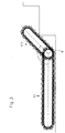
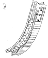
- the rope 10 is under tension. Due to this construction, the entire guide device can be used the numerous guide members 8 bend as in the Figures 6 and 7 is shown.
- the coil spring 10.5 pressed together. It exerts a force on the rope 10. The rope 10 thus strives to get the guidance device back into its straight Able to bring.
- the guide device can by an external force, for example by a steering device, arbitrarily brought into the curved shape, see Figures 6 and 7.
- the undercarriage then takes a turn. Hear the outside Influence on, the guide device automatically takes again rectilinear shape according to Figures 4 and 5. The steering is thus automatically withdrawn.
- cornering lie against each other Adjacent guide members 8 only along the inside of the curve a line together.
- FIG. 9 shows details of these guide elements.
- Figures 9a and 9b show one and the same guide member 8, once with a view of FIG Front ( Figure 9a) and once with a view of the back ( Figure 9b).
- Each guide member has two pins 8.1, 8.2, among other things two mounting holes 8.3, 8.4.
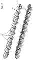
- the following can be seen from FIG. 8: For example, consider the three shown on the right Guide members 8 recognizes the second and third guide members one that the upper pin 8.1 of the third guide member with the Bore 8.3 of the second guide member is aligned, and that the lower Pin 8.2 of the third guide member with the lower bore 8.4 of the second guide member is aligned.
- FIG. 10 is a top view of two guide elements 8 which have been put together.
- an upper pin 8.1 engages in an upper bore 8.3.
- the lower pin 8.4 which is exposed.
- he has Cones in this representation have a frustoconical shape. The shape is however chosen in detail in such a way that a deflection from one another neighboring guide members 8 is possible relative to each other - see Figure 11.
- the mutually facing surfaces are from each other neighboring guide members 8 designed accordingly that a Deflection is possible. Note the arising when deflecting wedge-shaped gusset 8.5, 8.6 in Figure 11.
- the pin 8.4 has one at its root Cross section 8.4.1, which is formed from a circle. At his free At the end, however, it has a cross section 8.4.2, which consists of two A circular arc is formed, the centers of which M1 and M2 fall apart. This creates a grade 8.4.3 and a further grade 8.4.4 at the surface line.
- the structure of the individual caterpillar can be seen more clearly from FIG. Man again sees the chain 9.1 and the outer belt 9.2.
- the chain has that Building an ordinary bicycle chain.
- the single chain link points an angle bracket 9.1.1. This engages in a corresponding recess 8.7 in the guide members 8 - see Figure 9b.
- the outer belt is made up of a large number of belt links 9.2.1. This are made of rubber in the present case.
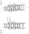
- Figures 14 and 15 show the structure of the chain 9.1 in more detail.
- the chain has pins 9.1.2 and surrounding them Sleeves 9.1.3.
- the sleeves are oversized compared to the pins, so that the curvature of the chain shown in Figure 15 is possible.
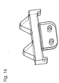
- the outer belt member shown in Figure 16 is equipped with two bumps.
- the outer belt member shown in Figure 17 has only a single hump on.
- Figures 16 and 17 leave an interesting detail recognize:
- the outer belt links have at both ends (in Seen in the direction of travel) each an inwardly angled leg on. This forms a contact surface.
- the legs rest on the relevant chain links of the chain 9.1. This results in a greater running stability.
- the guide member 8 according to FIG. 18 again shows that Angle plate 9.1.1 of the chain 9.1, which is guided in a recess 8.7.
- the holes 12, 13, 14 serve to receive a rope 10 (see figure 5).
- a rope 10 see figure 5
- One to three such ropes can optionally be used.
- the slots 15, 16 pass through the guide member 8. You serve for pushing through a flat bar, for example a steel bar.
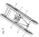
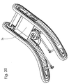
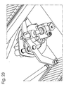
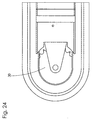
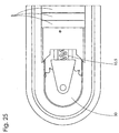
- Figures 19 and 20 show details of the steering drive under other a steering linkage 20, steering lever 21, a steering fork 22, one Pivotal point 23 for a spindle nut, a gear motor 24 for the Steering and a potentiometer 25, for example, for deceleration the caterpillar 9 can be used.
- a tub 26 is used to hold the battery.
- the spindle nut is in the center.
- the Chassis drives straight ahead.
- the control box 31 shown in FIG. 26 comprises an operating button 32 for reverse operation left / right.
- the operator can Driving forward or backward simultaneously with steering lock.
- An LED 33 indicates the state of the battery.
- a green indicator means for example, that the battery is still sufficiently charged.
- Another LED 34 lights up red when the emergency switch 35 has been actuated.
Landscapes
- Engineering & Computer Science (AREA)
- Chemical & Material Sciences (AREA)
- Animal Behavior & Ethology (AREA)
- General Health & Medical Sciences (AREA)
- Public Health (AREA)
- Veterinary Medicine (AREA)
- Health & Medical Sciences (AREA)
- Life Sciences & Earth Sciences (AREA)
- Combustion & Propulsion (AREA)
- Transportation (AREA)
- Mechanical Engineering (AREA)
- Handcart (AREA)
- Non-Deflectable Wheels, Steering Of Trailers, Or Other Steering (AREA)
Applications Claiming Priority (2)
| Application Number | Priority Date | Filing Date | Title |
|---|---|---|---|
| DE1999115482 DE19915482A1 (de) | 1999-04-07 | 1999-04-07 | Treppensteigvorrichtung, bspw. für Rollstühle |
| DE19915482 | 1999-04-07 |
Publications (2)
| Publication Number | Publication Date |
|---|---|
| EP1043007A2 true EP1043007A2 (fr) | 2000-10-11 |
| EP1043007A3 EP1043007A3 (fr) | 2001-09-19 |
Family
ID=7903657
Family Applications (1)
| Application Number | Title | Priority Date | Filing Date |
|---|---|---|---|
| EP00106917A Withdrawn EP1043007A3 (fr) | 1999-04-07 | 2000-03-31 | Dispositif pour monter les escaliers, en particulier pour les fauteuils roulants |
Country Status (2)
| Country | Link |
|---|---|
| EP (1) | EP1043007A3 (fr) |
| DE (2) | DE19915482A1 (fr) |
Cited By (1)
| Publication number | Priority date | Publication date | Assignee | Title |
|---|---|---|---|---|
| RU2547967C1 (ru) * | 2014-06-09 | 2015-04-10 | Николай Петрович Дядченко | Колесно-гусеничное шасси |
Families Citing this family (4)
| Publication number | Priority date | Publication date | Assignee | Title |
|---|---|---|---|---|
| DE10065694A1 (de) * | 2000-12-29 | 2002-07-18 | Dornier Tech Gmbh & Co | Einkaufsroller |
| CN105167927B (zh) * | 2015-09-17 | 2017-03-22 | 哈尔滨工程大学 | 一种轮履组合式爬楼梯轮椅 |
| JP6843354B2 (ja) * | 2017-05-11 | 2021-03-17 | 株式会社ジェイアール東日本物流 | 階段昇降装置 |
| EP3453370A1 (fr) | 2017-09-11 | 2019-03-13 | Scewo AG | Véhicule permettant le franchissement d'un escalier ou d'une rampe |
Citations (1)
| Publication number | Priority date | Publication date | Assignee | Title |
|---|---|---|---|---|
| DE3713564A1 (de) | 1987-04-23 | 1988-11-10 | Haas & Alber Haustechnik Und A | Treppensteigvorrichtung, beispielsweise fuer rollstuehle fuer gehunfaehige |
Family Cites Families (8)
| Publication number | Priority date | Publication date | Assignee | Title |
|---|---|---|---|---|
| GB218714A (en) * | 1923-12-21 | 1924-07-17 | Armstrong Siddeley Motors Ltd | Improvements in vehicles having self-laying tracks |
| US3869011A (en) * | 1973-01-02 | 1975-03-04 | Ramby Inc | Stair climbing tracked vehicle |
| GB1491555A (en) * | 1975-01-21 | 1977-11-09 | Ramby Inc | Stair climbing tracked vehicle |
| US4453611A (en) * | 1980-10-10 | 1984-06-12 | Stacy Jr Jack C | Terrain vehicle having a single, latterally bendable track |
| DE3316014A1 (de) * | 1983-05-03 | 1984-11-08 | HIRO LIFT Hillenkötter & Ronsieck GmbH, 4800 Bielefeld | Treppenfahrzeug |
| DE3610001A1 (de) * | 1986-03-25 | 1987-10-01 | Kloeckner Becorit Gmbh | Kurvengaengiges raupenfahrwerk |
| US4714125A (en) * | 1986-05-05 | 1987-12-22 | Stacy Jr Jack C | Single laterally bendable track snowmobile |
| DE3626238A1 (de) * | 1986-08-02 | 1988-02-18 | Kloeckner Becorit Gmbh | Lenkbares raupenfahrwerk |
-
1999
- 1999-04-07 DE DE1999115482 patent/DE19915482A1/de not_active Withdrawn
- 1999-06-04 DE DE29909795U patent/DE29909795U1/de not_active Expired - Lifetime
-
2000
- 2000-03-31 EP EP00106917A patent/EP1043007A3/fr not_active Withdrawn
Patent Citations (1)
| Publication number | Priority date | Publication date | Assignee | Title |
|---|---|---|---|---|
| DE3713564A1 (de) | 1987-04-23 | 1988-11-10 | Haas & Alber Haustechnik Und A | Treppensteigvorrichtung, beispielsweise fuer rollstuehle fuer gehunfaehige |
Cited By (1)
| Publication number | Priority date | Publication date | Assignee | Title |
|---|---|---|---|---|
| RU2547967C1 (ru) * | 2014-06-09 | 2015-04-10 | Николай Петрович Дядченко | Колесно-гусеничное шасси |
Also Published As
| Publication number | Publication date |
|---|---|
| EP1043007A3 (fr) | 2001-09-19 |
| DE19915482A1 (de) | 2000-10-19 |
| DE29909795U1 (de) | 1999-09-23 |
Similar Documents
| Publication | Publication Date | Title |
|---|---|---|
| DE1655512C3 (de) | Fahrzeug mit einem schwenkbaren Fahrwerk | |
| EP1129923B1 (fr) | Dispositif de transport | |
| DE3146550C2 (de) | Treppensteigende Rollstuhl-Transporteinrichtung | |
| DE3137254A1 (de) | Treppenkletternder fahrstuhltraeger | |
| DE4243812C2 (de) | Schiffs-Förderanlage | |
| DE3323023C2 (fr) | ||
| DE2362340C3 (de) | Karre zum Steigen auf einer Treppe | |
| DE3431610A1 (de) | Rolltreppe | |
| EP1301249B1 (fr) | Appareil de sport et de transport | |
| DE60004893T2 (de) | Beschleunigungsfahrsteig | |
| EP1043007A2 (fr) | Dispositif pour monter les escaliers, en particulier pour les fauteuils roulants | |
| DE2640128A1 (de) | Pistenpflegefahrzeug | |
| DE3804306C2 (fr) | ||
| DE19522939C2 (de) | Treppengängiges Fahrzeug | |
| DE3706239A1 (de) | Rollstuhl fuer wohnung, treppe und gelaende | |
| DE3843643A1 (de) | Schleppvorrichtung fuer fahrzeugraeder in autowaschanlagen | |
| DE4342054C1 (de) | Gestell zum Erlernen und Üben von Klettertechniken | |
| EP2300115A2 (fr) | Système de rail et planche de glisse associée | |
| EP0697322A1 (fr) | Dispositif de transport pouvant monter des escaliers | |
| DE20115012U1 (de) | Muskelkraftbetriebenes Fahrzeug mit einer Wippe | |
| EP0213394A1 (fr) | Tracteur à chenilles pour escalier | |
| WO2019120916A1 (fr) | Dispositif d'encerclement pour chaînes à rouleaux extérieures d'un dispositif de transport de personnes | |
| DE19515905A1 (de) | Fortbewegungsvorrichtung | |
| DE2611681C3 (de) | Gleiskette für geländegängige Fahrzeuge, insbesondere Panzerkampfwagen | |
| DE10059402B4 (de) | Schwenkliftgarage |
Legal Events
| Date | Code | Title | Description |
|---|---|---|---|
| PUAI | Public reference made under article 153(3) epc to a published international application that has entered the european phase |
Free format text: ORIGINAL CODE: 0009012 |
|
| AK | Designated contracting states |
Kind code of ref document: A2 Designated state(s): AT BE CH CY DE DK ES FI FR GB GR IE IT LI LU MC NL PT SE Kind code of ref document: A2 Designated state(s): DE FR GB IT |
|
| AX | Request for extension of the european patent |
Free format text: AL;LT;LV;MK;RO;SI |
|
| PUAL | Search report despatched |
Free format text: ORIGINAL CODE: 0009013 |
|
| AK | Designated contracting states |
Kind code of ref document: A3 Designated state(s): AT BE CH CY DE DK ES FI FR GB GR IE IT LI LU MC NL PT SE |
|
| AX | Request for extension of the european patent |
Free format text: AL;LT;LV;MK;RO;SI |
|
| AKX | Designation fees paid |
Free format text: DE FR GB IT |
|
| 17P | Request for examination filed |
Effective date: 20020615 |
|
| RAP1 | Party data changed (applicant data changed or rights of an application transferred) |
Owner name: GOBBERS, WALTER Owner name: GOBBERS, DIETER |
|
| 17Q | First examination report despatched |
Effective date: 20021004 |
|
| STAA | Information on the status of an ep patent application or granted ep patent |
Free format text: STATUS: THE APPLICATION IS DEEMED TO BE WITHDRAWN |
|
| 18D | Application deemed to be withdrawn |
Effective date: 20030415 |