EP1043036A2 - Oxygénateur sanguin - Google Patents
Oxygénateur sanguin Download PDFInfo
- Publication number
- EP1043036A2 EP1043036A2 EP00105777A EP00105777A EP1043036A2 EP 1043036 A2 EP1043036 A2 EP 1043036A2 EP 00105777 A EP00105777 A EP 00105777A EP 00105777 A EP00105777 A EP 00105777A EP 1043036 A2 EP1043036 A2 EP 1043036A2
- Authority
- EP
- European Patent Office
- Prior art keywords
- gas
- blood
- path
- valve seat
- oxygenation device
- Prior art date
- Legal status (The legal status is an assumption and is not a legal conclusion. Google has not performed a legal analysis and makes no representation as to the accuracy of the status listed.)
- Withdrawn
Links
- 239000008280 blood Substances 0.000 title claims abstract description 74
- 210000004369 blood Anatomy 0.000 title claims abstract description 74
- 239000012528 membrane Substances 0.000 claims abstract description 38
- 238000006213 oxygenation reaction Methods 0.000 claims abstract description 33
- 230000036772 blood pressure Effects 0.000 claims abstract description 12
- 230000001105 regulatory effect Effects 0.000 claims abstract description 3
- 238000011144 upstream manufacturing Methods 0.000 claims 2
- 239000007789 gas Substances 0.000 abstract description 77
- CURLTUGMZLYLDI-UHFFFAOYSA-N Carbon dioxide Chemical compound O=C=O CURLTUGMZLYLDI-UHFFFAOYSA-N 0.000 abstract description 4
- QVGXLLKOCUKJST-UHFFFAOYSA-N atomic oxygen Chemical compound [O] QVGXLLKOCUKJST-UHFFFAOYSA-N 0.000 abstract description 3
- 229910052760 oxygen Inorganic materials 0.000 abstract description 3
- 239000001301 oxygen Substances 0.000 abstract description 3
- 229910002092 carbon dioxide Inorganic materials 0.000 abstract description 2
- 239000001569 carbon dioxide Substances 0.000 abstract description 2
- 230000017531 blood circulation Effects 0.000 abstract 1
- 238000013022 venting Methods 0.000 abstract 1
- 238000005496 tempering Methods 0.000 description 2
- XLYOFNOQVPJJNP-UHFFFAOYSA-N water Substances O XLYOFNOQVPJJNP-UHFFFAOYSA-N 0.000 description 2
- MYMOFIZGZYHOMD-UHFFFAOYSA-N Dioxygen Chemical compound O=O MYMOFIZGZYHOMD-UHFFFAOYSA-N 0.000 description 1
- 230000000694 effects Effects 0.000 description 1
- 210000004072 lung Anatomy 0.000 description 1
- 239000000203 mixture Substances 0.000 description 1
- 230000002093 peripheral effect Effects 0.000 description 1
Images


Classifications
-
- A—HUMAN NECESSITIES
- A61—MEDICAL OR VETERINARY SCIENCE; HYGIENE
- A61M—DEVICES FOR INTRODUCING MEDIA INTO, OR ONTO, THE BODY; DEVICES FOR TRANSDUCING BODY MEDIA OR FOR TAKING MEDIA FROM THE BODY; DEVICES FOR PRODUCING OR ENDING SLEEP OR STUPOR
- A61M1/00—Suction or pumping devices for medical purposes; Devices for carrying-off, for treatment of, or for carrying-over, body-liquids; Drainage systems
- A61M1/14—Dialysis systems; Artificial kidneys; Blood oxygenators ; Reciprocating systems for treatment of body fluids, e.g. single needle systems for hemofiltration or pheresis
- A61M1/16—Dialysis systems; Artificial kidneys; Blood oxygenators ; Reciprocating systems for treatment of body fluids, e.g. single needle systems for hemofiltration or pheresis with membranes
- A61M1/1698—Blood oxygenators with or without heat-exchangers
-
- A—HUMAN NECESSITIES
- A61—MEDICAL OR VETERINARY SCIENCE; HYGIENE
- A61M—DEVICES FOR INTRODUCING MEDIA INTO, OR ONTO, THE BODY; DEVICES FOR TRANSDUCING BODY MEDIA OR FOR TAKING MEDIA FROM THE BODY; DEVICES FOR PRODUCING OR ENDING SLEEP OR STUPOR
- A61M1/00—Suction or pumping devices for medical purposes; Devices for carrying-off, for treatment of, or for carrying-over, body-liquids; Drainage systems
- A61M1/36—Other treatment of blood in a by-pass of the natural circulatory system, e.g. temperature adaptation, irradiation ; Extra-corporeal blood circuits
- A61M1/3621—Extra-corporeal blood circuits
- A61M1/3623—Means for actively controlling temperature of blood
-
- A—HUMAN NECESSITIES
- A61—MEDICAL OR VETERINARY SCIENCE; HYGIENE
- A61M—DEVICES FOR INTRODUCING MEDIA INTO, OR ONTO, THE BODY; DEVICES FOR TRANSDUCING BODY MEDIA OR FOR TAKING MEDIA FROM THE BODY; DEVICES FOR PRODUCING OR ENDING SLEEP OR STUPOR
- A61M1/00—Suction or pumping devices for medical purposes; Devices for carrying-off, for treatment of, or for carrying-over, body-liquids; Drainage systems
- A61M1/36—Other treatment of blood in a by-pass of the natural circulatory system, e.g. temperature adaptation, irradiation ; Extra-corporeal blood circuits
- A61M1/3621—Extra-corporeal blood circuits
- A61M1/3639—Blood pressure control, pressure transducers specially adapted therefor
-
- A—HUMAN NECESSITIES
- A61—MEDICAL OR VETERINARY SCIENCE; HYGIENE
- A61M—DEVICES FOR INTRODUCING MEDIA INTO, OR ONTO, THE BODY; DEVICES FOR TRANSDUCING BODY MEDIA OR FOR TAKING MEDIA FROM THE BODY; DEVICES FOR PRODUCING OR ENDING SLEEP OR STUPOR
- A61M2205/00—General characteristics of the apparatus
- A61M2205/33—Controlling, regulating or measuring
- A61M2205/3331—Pressure; Flow
Definitions
- the invention relates to a blood oxygenation device according to the preamble of claim 1.
- a blood oxygenation device of this type is known from EP 0 245 784 B1 known.
- the object of the invention is to achieve the blood oxygenation device to train such that your pressure regulator more accurate and faster works responsively.
- the invention is implemented by a blood oxygenation device, containing a blood path; a gas path that is separate from the blood path; a Gas exchange membrane assembly between a gas path section and one Blood path section for gas exchange between the blood of the blood path and the gas of the gas path, the gas exchange membrane assembly liquid-tight, but gas-permeable for gas exchange; on Pressure control valve through which the gas pressure prevailing in the gas path section depending on the blood pressure prevailing in the blood path section is automatically regulated; characterized in that the pressure control valve contains a gas pipe which is fluidly connected to the gas path and has an open end face designed as a valve seat; that the valve seat fluidly connected outside the gas pipe with the outside atmosphere is; that a valve body is arranged opposite the valve seat, which for more or less wide closing or opening of the valve seat in the gas pipe axial direction is movable relative to the valve seat; that the valve body on its from the side facing away from the valve seat towards the valve seat with a pressure corresponding to the respective blood pressure in the blood path can be applied, so that
- the pressure control valve of the invention works much more precisely and is shorter Response times than the known control devices of blood oxygenation devices.
- Fig. 1 shows a pressure regulator 2 of the blood oxygenation device according to the Invention as shown in the following drawings.
- the pressure regulator 2 can be in any horizontal, vertical or oblique Location can be used. It consists essentially of a tubular Membrane carrier 4 with a through opening 6; a gas pipe 8, which is inserted from one side into the through opening 6 and with a Union nut 10, which on the cylindrical membrane support 4th is screwed on an annular collar 12 against an opening shoulder 14 of the Through opening 6 is tensioned; a valve plate 16 which before Gas pipe 8 from the same side as this gas pipe 8 in the Through opening 6 is inserted and with a radially projecting Ring rib 18 can rest on a second opening paragraph 20, which has a smaller diameter than the first opening step 14; and one flexible, preferably also elastically stretchable valve membrane 22.
- the valve plate 16 has a cylindrical piston portion 24 which on other end of the through hole 6 in a cylindrical Bore section 26 of the through opening 6 axially relative to the gas pipe 8 is movably guided.
- the cylindrical bore section 26 has the smallest Diameter of the through opening 6 and is located at the other end the through hole 6 as the end in which the gas pipe 8 is inserted.
- the annular rib 18 projects radially over the entire circumference over the piston section 24 beyond.
- valve seat 28 The end face of the end of the protruding into the through opening 6 Gas pipe 8 is designed as a valve seat 28.
- This valve seat 28 is of the inner end face 30 of the valve plate 16 more or less far or fully lockable depending on the axial position of the Valve plate 16.
- the axial thickness of the annular rib 18 is dimensioned so that the Ring rib 18, and thus the valve plate 16, between the valve seat 28 of the Gas pipe 8 and the second opening paragraph 20 axial movements relative to stationary valve seat 28 can make.
- the distance of these axial movements is preferably in the range between approximately 1/10 mm to 4/10 mm, preferably around 2/10 mm.
- the inner end face 30 is at a distance from the valve seat 28 corresponding to the distance mentioned, for example of 2/10 mm if the Ring rib 18 abuts the second opening paragraph 20.
- the Valve opening gap 32 is at most as large as the distance mentioned.
- the axially outer line surface 34 is aligned Valve plate 16 with its adjacent outer end face 36 of the tubular Membrane carrier 4.
- On this end face 36 of the membrane carrier 4 is a outer circumferential area of the film-like or disk-like valve membrane 22 attached, for example glued or vulcanized. It stretches radially over the end of the passage opening 6.
- the valve membrane 22 is in contact the outer end face 34 of the valve plate 16, but is preferably on her not attached.
- Oxygenation compressed gas 40 compressed air, pure oxygen, with oxygen enriched gas or other gas mixtures
- the annular space 42 is through the adjacent peripheral walls of the gas pipe 8 and the Membrane carrier 4 formed between the two opening paragraphs 14 and 20.
- the radial bores 44 lead from the annular space 42 into the outside environment.
- the valve gap 32 is completely closed when the force on the side of the Blood 46 is greater than the force on the side of the gas 40. If the Force of the gas 40 approximates the force of the blood 46, then the gas presses the valve body 16 away from the valve seat 28 and the gas can through the Valve gap 32 escape into the outside atmosphere.
- the gas pressure follows in a ratio determined by the valve cross sections to the blood pressure.
- the Valve cross sections are preferably selected such that the gas pressure is at a maximum can reach blood pressure but cannot rise above it.
- the value by which the gas pressure is kept below the blood pressure depends on the cross-sectional ratio A: B.
- A is the Cross-sectional area of the cylindrical piston portion 24 and B of the Internal cross section of the gas pipe 8 on the valve seat 28.
- B By use of another cross section A: B the pressure of the gas can be higher than the pressure of the blood can be stopped.
- valve plate 16 is neither in one nor in the other axial direction preloaded by spring means.
- Spring means as is the case with the embodiment of FIG. 1, results the advantage that the "safety margin" between the blood pressure and the The higher the blood pressure, the greater the percentage gas pressure.
- the pressure regulator 2 serves the gas pressure in the blood oxygenation device of the gas 40 relative to the pressure of the blood 46 in the area of a gas exchange membrane to a desired, preferably adjustable ratio hold.
- the pressure regulator 2 should be as close as possible to the gas exchange membrane be placed in the bloodstream because at other points in the bloodstream and / or of the gas path in the blood oxygenation device there are different pressure values can, with the arrangement of the pressure regulator 2 there at an incorrect pressure of the gas in the area of the gas exchange membrane could lead.
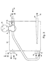
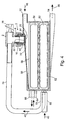
- the blood oxygenation device shown in FIG. 2 contains in a housing 50 between a blood inlet 52 and a blood outlet 54 one after the other Flow distributor 56, a heat exchanger 58, a gas exchange membrane 60 and a flow collector 62 for the blood 46.
- the heat exchanger 58 has a tempering water inlet 64 and one Tempering water outlet 66.
- the gas exchange membrane 60 can have any shape and exists preferably from a bundle of a large variety of capillary tubes which are flowed through by the gas inside and by the flow of blood 46 outside flow around. Oxygen passes through the gas exchange membrane 60 this gas stream into the blood stream, and vice versa carbon dioxide from the blood stream in the gas stream.
- the blood oxygenation device thus has the function of a Lung.
- the gas path of the gas 40 has one on the housing 50, to a compressed gas source connectable gas inlet 68 and a gas outlet 70.
- the pressure regulator 2 is on a wall of the Housing 50 attached such that the valve membrane 22 in a wall opening 72 of the housing 50 laterally limits the flow of the blood 46 at one point, which lies between the gas exchange membrane 60 and the blood outlet 54.
- the gas outlet 70 is through a line 74 to the gas pipe 8 of the pressure regulator 2 connected.
- the gas pipe 8 or the gas outlet line 74 connected to it can be via an adjustable throttle 76 can be connected to the outside atmosphere. If the throttle 76 is fully open, the pressure regulator 2 has none Control effect more. When the throttle 76 is completely closed, it results the largest possible gas pressure in pressure regulator 2. Thus, the throttle 76 the "working pressure" of the pressure regulator 2 can be set, either manually or automatically depending on an electronic control device, for example a heart-lung machine.
- a pressure display device can be attached to the gas pipe 8 of the pressure regulator 2 78 (pressure gauge) must be connected.
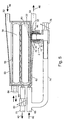
- FIG. 5 differs from FIGS. 1 to 3 only in that not the gas outlet 70, but the gas inlet 68 of the Gas exchange membrane 60 connected to the gas pipe 8 of the pressure regulator 2 is. 5, the throttle 76 at the input of the Pressure regulator 2 be completely closed, and the gas outlet 70 must be through a, preferably adjustable, throttle 80 are throttled so that in Oxygenator housing 50 creates the desired gas pressure.
Landscapes
- Health & Medical Sciences (AREA)
- Heart & Thoracic Surgery (AREA)
- Vascular Medicine (AREA)
- Hematology (AREA)
- Urology & Nephrology (AREA)
- Engineering & Computer Science (AREA)
- Anesthesiology (AREA)
- Biomedical Technology (AREA)
- Emergency Medicine (AREA)
- Life Sciences & Earth Sciences (AREA)
- Animal Behavior & Ethology (AREA)
- General Health & Medical Sciences (AREA)
- Public Health (AREA)
- Veterinary Medicine (AREA)
- Cardiology (AREA)
- External Artificial Organs (AREA)
Applications Claiming Priority (2)
| Application Number | Priority Date | Filing Date | Title |
|---|---|---|---|
| DE19916026 | 1999-04-09 | ||
| DE19916026A DE19916026A1 (de) | 1999-04-09 | 1999-04-09 | Blut-Oxygenier-Vorrichtung |
Publications (2)
| Publication Number | Publication Date |
|---|---|
| EP1043036A2 true EP1043036A2 (fr) | 2000-10-11 |
| EP1043036A3 EP1043036A3 (fr) | 2002-03-13 |
Family
ID=7904004
Family Applications (1)
| Application Number | Title | Priority Date | Filing Date |
|---|---|---|---|
| EP00105777A Withdrawn EP1043036A3 (fr) | 1999-04-09 | 2000-03-18 | Oxygénateur sanguin |
Country Status (3)
| Country | Link |
|---|---|
| EP (1) | EP1043036A3 (fr) |
| JP (1) | JP2000308681A (fr) |
| DE (1) | DE19916026A1 (fr) |
Cited By (2)
| Publication number | Priority date | Publication date | Assignee | Title |
|---|---|---|---|---|
| ITBS20120074A1 (it) * | 2012-04-27 | 2013-10-28 | Estor Spa | Procedimento e apparato per la rimozione di condensa da un dispositivo per il trattamento ematico extracorporeo per la rimozione di biossido di carbonio |
| EP3130365A1 (fr) * | 2011-05-20 | 2017-02-15 | Haemair Limited | Appareil d'échange en masse de gaz/fluide |
Family Cites Families (3)
| Publication number | Priority date | Publication date | Assignee | Title |
|---|---|---|---|---|
| IT1189119B (it) * | 1986-05-12 | 1988-01-28 | Dideco Spa | Ossigenatore a membrana microporosa |
| CA2001956A1 (fr) * | 1988-12-14 | 1990-06-14 | Ronald J. Leonard | Oxygenateur de sang a membrane |
| DE19820158A1 (de) * | 1998-05-06 | 1999-11-11 | Convergenza Ag Vaduz | Verfahren und Vorrichtung zur Blutoxygenierung |
-
1999
- 1999-04-09 DE DE19916026A patent/DE19916026A1/de not_active Withdrawn
-
2000
- 2000-03-18 EP EP00105777A patent/EP1043036A3/fr not_active Withdrawn
- 2000-04-05 JP JP2000103343A patent/JP2000308681A/ja active Pending
Cited By (3)
| Publication number | Priority date | Publication date | Assignee | Title |
|---|---|---|---|---|
| EP3130365A1 (fr) * | 2011-05-20 | 2017-02-15 | Haemair Limited | Appareil d'échange en masse de gaz/fluide |
| ITBS20120074A1 (it) * | 2012-04-27 | 2013-10-28 | Estor Spa | Procedimento e apparato per la rimozione di condensa da un dispositivo per il trattamento ematico extracorporeo per la rimozione di biossido di carbonio |
| WO2013160799A1 (fr) * | 2012-04-27 | 2013-10-31 | Estor Spa | Procédé et appareil d'élimination de la condensation à partir d'un dispositif pour le traitement hématique extracorporel pour l'élimination de dioxyde de carbone |
Also Published As
| Publication number | Publication date |
|---|---|
| DE19916026A1 (de) | 2000-10-12 |
| JP2000308681A (ja) | 2000-11-07 |
| EP1043036A3 (fr) | 2002-03-13 |
Similar Documents
| Publication | Publication Date | Title |
|---|---|---|
| DE69218213T2 (de) | Sammelleitung mit mehreren ventilen für ein medikamenten-infusionssystem | |
| DE69433584T2 (de) | Fluiddurchflußsteuervorrichtungen zum Regulieren des Durchflusses von Flüssigkeit oder Gas | |
| DE60303675T2 (de) | Verbindungselement und verbindungsvorrichtung für rohre | |
| DE69917527T2 (de) | Durchflussmengen-Regelventil, insbesondere für begaste Flüssigkeiten | |
| DE2947363A1 (de) | Exhalationsventil | |
| DE69123764T2 (de) | Vorrichtung für endlagedämpfung und geschwindigkeitsregelung der bewegung eines kolbens in einem druckmittelzylinder | |
| DE1959679A1 (de) | Filtereinsatz,insbesondere zum Beseitigen von Gas aus einer Stroemung | |
| DE10325846A1 (de) | Druckmindernder Regler | |
| DE112011102092T5 (de) | Druckreduziervorrichtung | |
| DE2745795A1 (de) | Atemgeraet mit verbessertem druckminderventil, insbesondere zum tauchen | |
| DE2818633A1 (de) | Regelventil | |
| DE3617726A1 (de) | Pneumatische feder | |
| DE3110907A1 (de) | Ventil od. dgl. organ fuer hydraulische systeme | |
| DE4127938A1 (de) | Saugregler fuer eine pleurale drainagevorrichtung | |
| DE4325837C2 (de) | Sicherheitsverbinder für die Infusionstherapie | |
| DE60020826T2 (de) | Gerät zur reduzierung von fluidrücklauf durch ein medizinisches ventil | |
| EP1689940B1 (fr) | Limiteur de debit | |
| DE69832988T2 (de) | Druckausgleichventil | |
| DE69727678T2 (de) | Activierungsstift | |
| DE102017000136B4 (de) | Axial-Steuerventil zur Steuerung des Volumenstroms in einer Gasleitung | |
| DE60109859T2 (de) | Pumpeinheit für ein Fluid, insbesondere Blut | |
| DE68910028T2 (de) | Halterung mit Strömungsweg für medizinischen Wärmetauscher. | |
| DE2531825C3 (de) | Vorrichtung zum Konstanthalten des Durchflusses einer Flüssigkeit | |
| DE2133422A1 (de) | Druckminderventil | |
| DE2851192C2 (de) | Ventil |
Legal Events
| Date | Code | Title | Description |
|---|---|---|---|
| PUAI | Public reference made under article 153(3) epc to a published international application that has entered the european phase |
Free format text: ORIGINAL CODE: 0009012 |
|
| AK | Designated contracting states |
Kind code of ref document: A2 Designated state(s): AT BE CH CY DE DK ES FI FR GB GR IE IT LI LU MC NL PT SE |
|
| AX | Request for extension of the european patent |
Free format text: AL;LT;LV;MK;RO;SI |
|
| PUAL | Search report despatched |
Free format text: ORIGINAL CODE: 0009013 |
|
| AK | Designated contracting states |
Kind code of ref document: A3 Designated state(s): AT BE CH CY DE DK ES FI FR GB GR IE IT LI LU MC NL PT SE |
|
| AX | Request for extension of the european patent |
Free format text: AL;LT;LV;MK;RO;SI |
|
| AKX | Designation fees paid | ||
| REG | Reference to a national code |
Ref country code: DE Ref legal event code: 8566 |
|
| STAA | Information on the status of an ep patent application or granted ep patent |
Free format text: STATUS: THE APPLICATION IS DEEMED TO BE WITHDRAWN |
|
| 18D | Application deemed to be withdrawn |
Effective date: 20020914 |